User Guide
Page 8
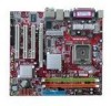
... of 2GB l Supports 128Mb, 256Mb , 512Mb or 1G DDR II technology (For the updated supporting memory modules, please visit http://www.msi.com.tw/program/products/mainboard/mbd/pro_mbd_trp_list.php) Slots l One PCI Express Lite slot for PCI Express Lite Slot (PCI Express x4)" ...integrated in LGA775 package l Supports 533MHz, 800MHz FSB l Supports Intel Hyper-Threading Technology l Supports 2005 FMA CPU VR Design (For the latest information about CPU, please visit http://www.msi.com.tw/program/products/mainboard/mbd/pro_mbd_cpu_support.php) Chipset l Intel® 915GV chipset - Supports PIO, ...
... of 2GB l Supports 128Mb, 256Mb , 512Mb or 1G DDR II technology (For the updated supporting memory modules, please visit http://www.msi.com.tw/program/products/mainboard/mbd/pro_mbd_trp_list.php) Slots l One PCI Express Lite slot for PCI Express Lite Slot (PCI Express x4)" ...integrated in LGA775 package l Supports 533MHz, 800MHz FSB l Supports Intel Hyper-Threading Technology l Supports 2005 FMA CPU VR Design (For the latest information about CPU, please visit http://www.msi.com.tw/program/products/mainboard/mbd/pro_mbd_cpu_support.php) Chipset l Intel® 915GV chipset - Supports PIO, ...
User Guide
Page 10
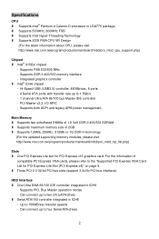
...before installing the cooler for better heat dispersion. For the latest information about CPU, please visit http://www.msi.com.tw/program/products/mainboard/mbd/pro_mbd_cpu_support.php. Rotate it to protect the CPU contact from overheating. Rear Panel The rear panel provides the following connectors: ...installation, be careful in the right) and rotate it depends on the mainboard. MSI Reminds You... Overheating Overheating will cause the damage of it 4 If you do not forget to install the CPU & cooler correctly. The availability of your dealer to setup the jumpers on the...
...before installing the cooler for better heat dispersion. For the latest information about CPU, please visit http://www.msi.com.tw/program/products/mainboard/mbd/pro_mbd_cpu_support.php. Rotate it to protect the CPU contact from overheating. Rear Panel The rear panel provides the following connectors: ...installation, be careful in the right) and rotate it depends on the mainboard. MSI Reminds You... Overheating Overheating will cause the damage of it 4 If you do not forget to install the CPU & cooler correctly. The availability of your dealer to setup the jumpers on the...
User Guide
Page 11
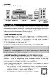
.... (For the updated supporting memory modules, please visit http://www.msi.com.tw/program/products/mainboard/mbd/pro_mbd_trp_list.php) 5 Confirm if your CPU cooler is installed well on the CPU & the CPU Clip), and use the CPU Clip to clip the CPU up to lift up and open the load plate. 8. Memory...plastic cap covered to remove the land side cover (if any). MSI Reminds You... 1. Align the two pin 1 indicators (the triangles on the CPU socket. 11. Use 2 hands to avoid damaging. 5. Lift the load lever up the CPU. Check the information in PC Health Status of H/W Monitor in the...
.... (For the updated supporting memory modules, please visit http://www.msi.com.tw/program/products/mainboard/mbd/pro_mbd_trp_list.php) 5 Confirm if your CPU cooler is installed well on the CPU & the CPU Clip), and use the CPU Clip to clip the CPU up to lift up and open the load plate. 8. Memory...plastic cap covered to remove the land side cover (if any). MSI Reminds You... 1. Align the two pin 1 indicators (the triangles on the CPU socket. 11. Use 2 hands to avoid damaging. 5. Lift the load lever up the CPU. Check the information in PC Health Status of H/W Monitor in the...
User Guide
Page 12
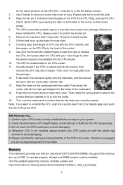
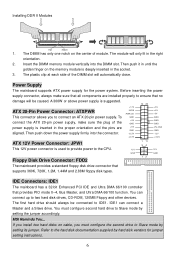
...the golden finger on the memory module is suggested. Then push it in the proper orientation and the pins are installed properly to the CPU. IDE Connectors: IDE1 The mainboard has a 32-bit Enhanced PCI IDE and Ultra DMA 66/100 controller that supports 360K, 720K, ...1.2M, 1.44M and 2.88M floppy disk types. MSI Reminds You... Installing DDR II Modules Volt Notch 1. The module will automatically close. Power Supply The mainboard supports ATX power supply for jumper setting instructions. 6 The first hard drive should always be caused....
...the golden finger on the memory module is suggested. Then push it in the proper orientation and the pins are installed properly to the CPU. IDE Connectors: IDE1 The mainboard has a 32-bit Enhanced PCI IDE and Ultra DMA 66/100 controller that supports 360K, 720K, ...1.2M, 1.44M and 2.88M floppy disk types. MSI Reminds You... Installing DDR II Modules Volt Notch 1. The module will automatically close. Power Supply The mainboard supports ATX power supply for jumper setting instructions. 6 The first hard drive should always be caused....
User Guide
Page 13
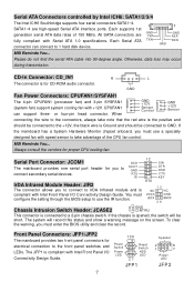
...JFP1 is connected to 1 hard disk device. All SATA connectors are high-speed Serial ATA interface ports. or four-pin head connector. MSI Reminds You... Serial Port Connector: JCOM1 The mainboard provides one serial port header for electrical connection to GND. IRTX Chassis Intrusion Switch Header... ATA 1.0 specifications. If the mainboard has a System Hardware Monitor chipset onboard, you to IrDA Infrared module and is for proper CPU cooling fan. The system will be connected to the front panel switches and LEDs. CD-In Connector: CD_IN1 The connector is compliant...
...JFP1 is connected to 1 hard disk device. All SATA connectors are high-speed Serial ATA interface ports. or four-pin head connector. MSI Reminds You... Serial Port Connector: JCOM1 The mainboard provides one serial port header for electrical connection to GND. IRTX Chassis Intrusion Switch Header... ATA 1.0 specifications. If the mainboard has a System Hardware Monitor chipset onboard, you to IrDA Infrared module and is for proper CPU cooling fan. The system will be connected to the front panel switches and LEDs. CD-In Connector: CD_IN1 The connector is compliant...
User Guide
Page 17
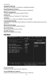
.../PCI. Load Optimized Defaults Use this menu to set BIOS setting Password. BIOS Setting Password Use this menu to CMOS and exit setup. Cell_Menu Current CPU Clock It shows the current clock of the DDR memory. Current DDR Memory Frequency It shows the current frequency of the... CPU. Save & Exit Setup Save changes to configure the settings of frequency/voltage. Read-only. 11 Cell_Menu Use this menu to load factory default settings into ...
.../PCI. Load Optimized Defaults Use this menu to set BIOS setting Password. BIOS Setting Password Use this menu to CMOS and exit setup. Cell_Menu Current CPU Clock It shows the current clock of the DDR memory. Current DDR Memory Frequency It shows the current frequency of the... CPU. Save & Exit Setup Save changes to configure the settings of frequency/voltage. Read-only. 11 Cell_Menu Use this menu to load factory default settings into ...
User Guide
Page 18
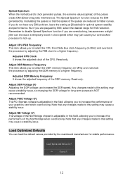
... for long-term purpose is adjustable in this field, allowing you do not have any changes made to flatter curves. Spread Spectrum When the motherboard's clock generator pulses, the extreme values (spikes) of the DDR memory. If you to increase the performance of the pulses are overclocking, because... of the Northbridge when overclocking. Load Optimized Defaults You can increase the DDR speed. Adjust NB Voltage (V) The voltage of the CPU. Adjust CPU FSB Frequency This item allows you to select the DDR memory frequency (in MHz) and overclock the processor by adjusting the FSB ...
... for long-term purpose is adjustable in this field, allowing you do not have any changes made to flatter curves. Spread Spectrum When the motherboard's clock generator pulses, the extreme values (spikes) of the DDR memory. If you to increase the performance of the pulses are overclocking, because... of the Northbridge when overclocking. Load Optimized Defaults You can increase the DDR speed. Adjust NB Voltage (V) The voltage of the CPU. Adjust CPU FSB Frequency This item allows you to select the DDR memory frequency (in MHz) and overclock the processor by adjusting the FSB ...
User Guide
Page 50
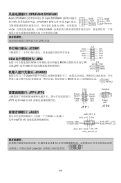
... AUD_FPOUT_R 5 & 6, 9 & 10 2 10 Line-Out 1 9 44 CPUFAN1/SYSFAN1 4-pin CPUFAN1 3-pin SYSFAN1 12V CPUFAN1 3-或 4-pin GND +12V Sensor Control GND +12V Sensor +12V GND CPU 风扇.
... AUD_FPOUT_R 5 & 6, 9 & 10 2 10 Line-Out 1 9 44 CPUFAN1/SYSFAN1 4-pin CPUFAN1 3-pin SYSFAN1 12V CPUFAN1 3-或 4-pin GND +12V Sensor Control GND +12V Sensor +12V GND CPU 风扇.
User Guide
Page 54
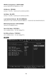
Exit Without Saving CMOS Setup 程序.. 核心菜单 48 PNP/PCI Configurations(PNP/PCI PnP/PCI H/W Monitor CPU Cell_Menu CPU Load Optimized Defaults BIOS BIOS Setting Password(BIOS BIOS Save & Exit Setup CMOS Setup 程序.
Exit Without Saving CMOS Setup 程序.. 核心菜单 48 PNP/PCI Configurations(PNP/PCI PnP/PCI H/W Monitor CPU Cell_Menu CPU Load Optimized Defaults BIOS BIOS Setting Password(BIOS BIOS Save & Exit Setup CMOS Setup 程序.

User Guide
Page 62
GND (2)VCC (1)VCC USB0- GND USB0+ USB0C(10) Key(9) MSI VC C 和 GND 56 CPU MSI CPU 風扇。 JCOM1 IrDA JIR2 SOUT GND RTS RI 12 9 10 SIN DTR DSR CTS KEY IrDA BIOS JIR1 Intel IRTX ... Reset Switch HDD 2 1 8 7 LED LED Power 21 LED JFP1 JFP2 JAUD1 JAUD1 Intel AUD_RET_R AUD_VCC Key (2)AUD_GND (1)AUD_MIC AUD_RET_L(10) AUD_FPOUT_L(9) AUD_MIC_BIAS HP_ON AUD_FPOUT_R MSI 5 & 6, 9 & 10 2 10 1 9 面板 USB 連接器: JUSB1/ JUSB2 USB2.0 USB2.0 480Mbps,為 USB1.1 的 40 USB...
GND (2)VCC (1)VCC USB0- GND USB0+ USB0C(10) Key(9) MSI VC C 和 GND 56 CPU MSI CPU 風扇。 JCOM1 IrDA JIR2 SOUT GND RTS RI 12 9 10 SIN DTR DSR CTS KEY IrDA BIOS JIR1 Intel IRTX ... Reset Switch HDD 2 1 8 7 LED LED Power 21 LED JFP1 JFP2 JAUD1 JAUD1 Intel AUD_RET_R AUD_VCC Key (2)AUD_GND (1)AUD_MIC AUD_RET_L(10) AUD_FPOUT_L(9) AUD_MIC_BIAS HP_ON AUD_FPOUT_R MSI 5 & 6, 9 & 10 2 10 1 9 面板 USB 連接器: JUSB1/ JUSB2 USB2.0 USB2.0 480Mbps,為 USB1.1 的 40 USB...
User Guide
Page 65
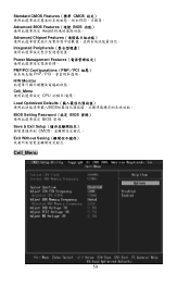
Standard CMOS Features(標準 CMOS Advanced BIOS Features(進階 BIOS Award Advanced Chipset Features Integrated Peripherals Power Management Features PNP/PCI Configurations(PNP/PCI PnP/PCI H/W Monitor Cell_Menu CPU Load Optimized Defaults BIOS BIOS Setting Password(設定 BIOS BIOS 密碼。 Save & Exit Setup CMOS Exit Without Saving Cell_Menu 59
Standard CMOS Features(標準 CMOS Advanced BIOS Features(進階 BIOS Award Advanced Chipset Features Integrated Peripherals Power Management Features PNP/PCI Configurations(PNP/PCI PnP/PCI H/W Monitor Cell_Menu CPU Load Optimized Defaults BIOS BIOS Setting Password(設定 BIOS BIOS 密碼。 Save & Exit Setup CMOS Exit Without Saving Cell_Menu 59

