
User Manual
Page 17
... note that the clip-ends are correctly inserted. Press down the cooler until its four clips get wedged into the holes of the CPU is 20 cycles. Push down the load lever lightly onto the load plate, and then secure the lever with the hook under retention tab. 10. Confirm if... the plastic cap covered (shown in Figure 1) to fasten the cooler. Do not touch the CPU socket pins to lock the hooks. 12. MS-7058 ATX Mainboard 9. Therefore we suggest you do not plug/unplug the CPU too often. Turn over the mainboard to confirm that the mating/unmating durability of...
... note that the clip-ends are correctly inserted. Press down the cooler until its four clips get wedged into the holes of the CPU is 20 cycles. Push down the load lever lightly onto the load plate, and then secure the lever with the hook under retention tab. 10. Confirm if... the plastic cap covered (shown in Figure 1) to fasten the cooler. Do not touch the CPU socket pins to lock the hooks. 12. MS-7058 ATX Mainboard 9. Therefore we suggest you do not plug/unplug the CPU too often. Turn over the mainboard to confirm that the mating/unmating durability of...

User Manual
Page 20
... pins are installed properly to connect an ATX 24-pin power supply. ATX 24-Pin Power Connector: ATX1 This connector allows you 'd like . You may use the 20-pin ATX power supply power supply as you like to use the 20-pin ATX power supply, please plug your power supply... hand). JPW1 42 31 JPW1 Pin Definition PIN SIGNAL 1 GND 2 GND 3 12V 4 12V MSI Reminds You... 1. ATX 12V power connection should be caused. Hardware Setup Power Supply The mainboard supports ATX power supply for system stability. 3. Then push down the power supply firmly into the connector. Power...
... pins are installed properly to connect an ATX 24-pin power supply. ATX 24-Pin Power Connector: ATX1 This connector allows you 'd like . You may use the 20-pin ATX power supply power supply as you like to use the 20-pin ATX power supply, please plug your power supply... hand). JPW1 42 31 JPW1 Pin Definition PIN SIGNAL 1 GND 2 GND 3 12V 4 12V MSI Reminds You... 1. ATX 12V power connection should be caused. Hardware Setup Power Supply The mainboard supports ATX power supply for system stability. 3. Then push down the power supply firmly into the connector. Power...

User Manual
Page 24
... 13 SELECT Select 14 AUTO FEED# Automatic Feed 15 ERR# Error 16 INIT# Initialize Printer 17 SLIN# Select In 18 GND Ground 19 GND Ground 20 GND Ground 21 GND Ground 22 GND Ground 23 GND Ground 24 GND Ground 25 GND Ground E2-13 Hardware Setup Parallel Port Connector: LPT1...
... 13 SELECT Select 14 AUTO FEED# Automatic Feed 15 ERR# Error 16 INIT# Initialize Printer 17 SLIN# Select In 18 GND Ground 19 GND Ground 20 GND Ground 21 GND Ground 22 GND Ground 23 GND Ground 24 GND Ground 25 GND Ground E2-13 Hardware Setup Parallel Port Connector: LPT1...
User Manual
Page 31
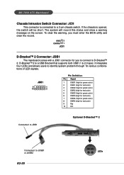
To clear the warning, you to connect to JUSB1 or JUSB2 E2-20 LEDs JDB1 9 1 10 2 Pin Definition Pin Signal 1 DBG1 (high for green color) 2 DBR1 (high for red color) 3 DBG2 (high for green color) 4 DBR2 (high for ... D-Bracket™ 2 Connected to D-Bracket™ 2. D-Bracket™ 2 is opened, the switch will record this status and show a warning message on the screen. MS-7058 ATX Mainboard Chassis Intrusion Switch Connector: JCI1 This connector is connected to identify system problem through 16 various combinations of LED signals. If the chassis is...
To clear the warning, you to connect to JUSB1 or JUSB2 E2-20 LEDs JDB1 9 1 10 2 Pin Definition Pin Signal 1 DBG1 (high for green color) 2 DBR1 (high for red color) 3 DBG2 (high for green color) 4 DBR2 (high for ... D-Bracket™ 2 Connected to D-Bracket™ 2. D-Bracket™ 2 is opened, the switch will record this status and show a warning message on the screen. MS-7058 ATX Mainboard Chassis Intrusion Switch Connector: JCI1 This connector is connected to identify system problem through 16 various combinations of LED signals. If the chassis is...