
User Guide
Page 4
...- Do not leave this User's Manual for technical guide, BIOS updates, driver updates, and other information: http://www.msi.com.tw & http://www.msi. CAUTION: Danger of the following help resources for further guidance. † Visit the MSI homepage & FAQ site for future reference. 3. iv Always read... cause electrical s h oc k . 11. com.tw/program/service/faq/faq/esc_faq_list.php † Contact our technical staff at: support@msi.com.tw Safety Instructions 1. Lay this equipment away from overheating. Replace only with your place of the power source and adjust properly 110/220V...
...- Do not leave this User's Manual for technical guide, BIOS updates, driver updates, and other information: http://www.msi.com.tw & http://www.msi. CAUTION: Danger of the following help resources for further guidance. † Visit the MSI homepage & FAQ site for future reference. 3. iv Always read... cause electrical s h oc k . 11. com.tw/program/service/faq/faq/esc_faq_list.php † Contact our technical staff at: support@msi.com.tw Safety Instructions 1. Lay this equipment away from overheating. Replace only with your place of the power source and adjust properly 110/220V...
User Guide
Page 6
... Chipset Features 3-11 Integrated Peripherals 3-12 Power Management Setup 3-17 PNP/PCI Configurations 3-20 H/W Monitor ...3-22 Cell Menu ...3-23 Load Fail-Safe/Optimized Defaults 3-30 BIOS Setting Password 3-31 Chapter 4. IrDA Infrared Module Header: JIR1 2-20 IEEE 1394 Connectors: J1394_1 (Optional 2-21 D-BracketTM 2 Connector: JDB1 2-22 Buuton ...2-24 Clear CMOS ...Access Point 4-6 Terminology 4-6 Access Point Mode 4-7 WLAN Card Mode 4-8 Live Update ...4-9 MEGA STICK ...4-10 Basic Function 4-10 Non-Unicode programs supported 4-12 Core Center (for AMD K8 Processor 4-14 vi
... Chipset Features 3-11 Integrated Peripherals 3-12 Power Management Setup 3-17 PNP/PCI Configurations 3-20 H/W Monitor ...3-22 Cell Menu ...3-23 Load Fail-Safe/Optimized Defaults 3-30 BIOS Setting Password 3-31 Chapter 4. IrDA Infrared Module Header: JIR1 2-20 IEEE 1394 Connectors: J1394_1 (Optional 2-21 D-BracketTM 2 Connector: JDB1 2-22 Buuton ...2-24 Clear CMOS ...Access Point 4-6 Terminology 4-6 Access Point Mode 4-7 WLAN Card Mode 4-8 Live Update ...4-9 MEGA STICK ...4-10 Basic Function 4-10 Non-Unicode programs supported 4-12 Core Center (for AMD K8 Processor 4-14 vi

User Guide
Page 7
... Installation 6-2 NVIDIA nForce4 System Driver 6-2 Realtek AC97 Audio Driver 6-5 Utility Installation 6-6 vii Installation of RAID Configurations 5-2 RAID Configuration 5-3 Basic Configuration Instructions 5-3 Setting Up the NVRAID BIOS 5-3 NVIDIA RAID Untility Installation 5-7 Installing the RAID Driver (for bootable RAID Array 5-7 Installing the NVIDIA RAID Software Under W indows (for Non-bootable RAID Array 5-9 Initializing...
... Installation 6-2 NVIDIA nForce4 System Driver 6-2 Realtek AC97 Audio Driver 6-5 Utility Installation 6-6 vii Installation of RAID Configurations 5-2 RAID Configuration 5-3 Basic Configuration Instructions 5-3 Setting Up the NVRAID BIOS 5-3 NVIDIA RAID Untility Installation 5-7 Installing the RAID Driver (for bootable RAID Array 5-7 Installing the NVIDIA RAID Software Under W indows (for Non-bootable RAID Array 5-9 Initializing...
User Guide
Page 11
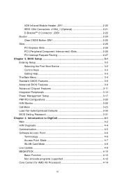
... SPDIF out - 1 coaxial SPDIF out - 1 IrDA pinheader - 1 CD-In pinheader - 1 D-Bracket2 pinheader - 2 IEEE1394 ports (Rear * 1 / Front * 1)(Optional) - 10 USB1.1/2.0 ports (Rear * 4 / Front * 6) BIOS † The mainboard BIOS provides "Plug & Play" BIOS which detects the peripheral devices and expansion cards of the board automatically. † The mainboard provides a Desktop Management Interface (DMI) function which...
... SPDIF out - 1 coaxial SPDIF out - 1 IrDA pinheader - 1 CD-In pinheader - 1 D-Bracket2 pinheader - 2 IEEE1394 ports (Rear * 1 / Front * 1)(Optional) - 10 USB1.1/2.0 ports (Rear * 4 / Front * 6) BIOS † The mainboard BIOS provides "Plug & Play" BIOS which detects the peripheral devices and expansion cards of the board automatically. † The mainboard provides a Desktop Management Interface (DMI) function which...
User Guide
Page 31
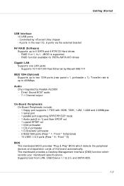
... instructions. You can connect a Master and a Slave drive. IDE2 IDE1 IDE1 (Primary IDE Connector) The first hard drive should always be short. MSI Reminds You... You must enter the BIOS utility and clear the record. IDE2 (Secondary IDE Connector) IDE2 can also connect a Master and a Slave drive. If you must configure the...
... instructions. You can connect a Master and a Slave drive. IDE2 IDE1 IDE1 (Primary IDE Connector) The first hard drive should always be short. MSI Reminds You... You must enter the BIOS utility and clear the record. IDE2 (Secondary IDE Connector) IDE2 can also connect a Master and a Slave drive. If you must configure the...

User Guide
Page 34
... front panel Right channel audio signal return from front panel Reserved for future use the IR function. You must configure the setting through the BIOS setup to use to control headphone amplifier No pin Left channel audio signal to front panel Left channel audio signal return from front panel... MSI Reminds You... If you to connect to IrDA Infrared module. JIR1 is compliant with Intel® Front Panel I /O Connectivity Design Guide. Otherwise, the Line...
... front panel Right channel audio signal return from front panel Reserved for future use the IR function. You must configure the setting through the BIOS setup to use to control headphone amplifier No pin Left channel audio signal to front panel Left channel audio signal return from front panel... MSI Reminds You... If you to connect to IrDA Infrared module. JIR1 is compliant with Intel® Front Panel I /O Connectivity Design Guide. Otherwise, the Line...
User Guide
Page 37
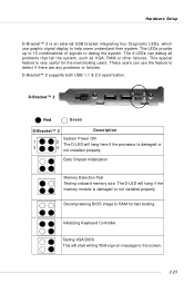
Testing VGA BIOS This will hang here if the processor is damaged or not installed properly. The LEDs provide up to 16 combinations of signals to detect if ...™ 2 1 2 3 4 Red Green D-Bracket™ 2 Description System Power ON 1 2 The D-LED will start writing VGA sign-on message to RAM for the overclocking users. Decompressing BIOS image to the screen. 2-23 Hardware Setup D-Bracket™ 2 is very useful for fast booting. These users can debug all problems that fail the system...
Testing VGA BIOS This will hang here if the processor is damaged or not installed properly. The LEDs provide up to 16 combinations of signals to detect if ...™ 2 1 2 3 4 Red Green D-Bracket™ 2 Description System Power ON 1 2 The D-LED will start writing VGA sign-on message to RAM for the overclocking users. Decompressing BIOS image to the screen. 2-23 Hardware Setup D-Bracket™ 2 is very useful for fast booting. These users can debug all problems that fail the system...
User Guide
Page 38
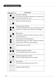
... (like 3 4 brand name, system bus, etc...) Testing RTC (Real Time Clock) Initializing Video Interface This will start showing information about logo, processor brand name, etc... BIOS Sign On This will set low stack and boot via INT 19h.
... (like 3 4 brand name, system bus, etc...) Testing RTC (Real Time Clock) Initializing Video Interface This will start showing information about logo, processor brand name, etc... BIOS Sign On This will set low stack and boot via INT 19h.
User Guide
Page 40
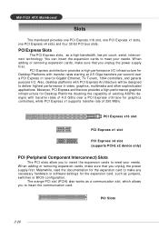
... to deliver highest performance in video, graphics, multimedia and other sophisticated applications. Meanwhile, read the documentation for the expansion card, such as jumpers, switches or BIOS configuration. PCI Slots 2-26 The orange PCI slot (PCI4) also works as a high-bandwidth, low pin count, serial, interconnect technology. PCI Express architecture provides a high...
... to deliver highest performance in video, graphics, multimedia and other sophisticated applications. Meanwhile, read the documentation for the expansion card, such as jumpers, switches or BIOS configuration. PCI Slots 2-26 The orange PCI slot (PCI4) also works as a high-bandwidth, low pin count, serial, interconnect technology. PCI Express architecture provides a high...
User Guide
Page 42
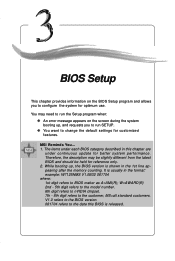
...should be held for optimum use. V1.0 refers to the BIOS version. 061704 refers to BIOS maker as A=AMI(R); It is released. 3-1 Therefore, the description may need to run SETUP. ” You want to the customer, MS=all standard customers. MSI Reminds You... 1. While booting up , and requests you ...to run the Setup program when: ” An error message appears on the BIOS Setup program and allows you to configure the system for reference only. 2. W=AWARD...
...should be held for optimum use. V1.0 refers to the BIOS version. 061704 refers to BIOS maker as A=AMI(R); It is released. 3-1 Therefore, the description may need to run SETUP. ” You want to the customer, MS=all standard customers. MSI Reminds You... 1. While booting up , and requests you ...to run the Setup program when: ” An error message appears on the BIOS Setup program and allows you to configure the system for reference only. 2. W=AWARD...
User Guide
Page 43
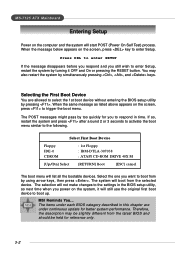
...the screen, press to trigger the boot menu. You may be slightly different from the latest BIOS and should be held for you want to the following. Select the one you to enter Setup. MSI Reminds You... The POST messages might pass by using arrow keys, then press . The items... under continuous update for better system performance. Selecting the First Boot Device You are under each BIOS category described in this chapter are allowed to boot...
...the screen, press to trigger the boot menu. You may be slightly different from the latest BIOS and should be held for you want to the following. Select the one you to enter Setup. MSI Reminds You... The POST messages might pass by using arrow keys, then press . The items... under continuous update for better system performance. Selecting the First Boot Device You are under each BIOS category described in this chapter are allowed to boot...
User Guide
Page 44
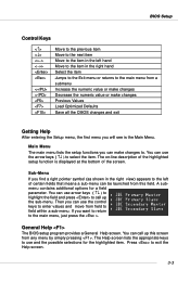
... the item Jumps to the Exit menu or returns to the main menu from this screen from field to select the item. General Help The BIOS setup program provides a General Help screen. Press to . Sub-Menu If you will see is displayed at the bottom of the screen. You can ...selections for a field parameter. The on-line description of the highlighted setup function is the Main Menu. A submenu contains additional options for the highlighted item. BIOS Setup Control Keys Enter> Move to the previous item Move to the next item Move to the item in the left of certain fields that...
... the item Jumps to the Exit menu or returns to the main menu from this screen from field to select the item. General Help The BIOS setup program provides a General Help screen. Press to . Sub-Menu If you will see is displayed at the bottom of the screen. You can ...selections for a field parameter. The on-line description of the highlighted setup function is the Main Menu. A submenu contains additional options for the highlighted item. BIOS Setup Control Keys Enter> Move to the previous item Move to the next item Move to the item in the left of certain fields that...

User Guide
Page 45
The Main Menu allows you enter Phoenix-Award® BIOS CMOS Setup Utility, the Main Menu will appear on the screen. Use arrow keys to select among the items and press to select from twelve ... your system's performance. Advanced Chipset Features Use this menu to change the values in the chipset registers and optimize your settings for power management. Advanced BIOS Features Use this menu to setup the items of AWARD® special enhanced features. H/W Monitor Use this menu to specify your system supports PnP/PCI...
The Main Menu allows you enter Phoenix-Award® BIOS CMOS Setup Utility, the Main Menu will appear on the screen. Use arrow keys to select among the items and press to select from twelve ... your system's performance. Advanced Chipset Features Use this menu to change the values in the chipset registers and optimize your settings for power management. Advanced BIOS Features Use this menu to setup the items of AWARD® special enhanced features. H/W Monitor Use this menu to specify your system supports PnP/PCI...

User Guide
Page 46
BIOS Setup Load Optimized Defaults Use this menu to CMOS and exit setup. Exit Without Saving Abandon all changes and exit setup. 3-5 BIOS Setting Password Use this menu to load the BIOS values for BIOS. Save & Exit Setup Save changes to set the password for the best system performance, but the system stability may be affected.
BIOS Setup Load Optimized Defaults Use this menu to CMOS and exit setup. Exit Without Saving Abandon all changes and exit setup. 3-5 BIOS Setting Password Use this menu to load the BIOS values for BIOS. Save & Exit Setup Save changes to set the password for the best system performance, but the system stability may be affected.
User Guide
Page 47
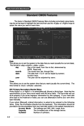
... want (usually the current date). Cylinder Number of your drive must match with the drive table. month The month from Sun to Sat, determined by BIOS. date The date from the keyboard. Capacity The formatted size of the week, from Jan. Read-only. year The year can be keyed by users...
... want (usually the current date). Cylinder Number of your drive must match with the drive table. month The month from Sun to Sat, determined by BIOS. date The date from the keyboard. Capacity The formatted size of the week, from Jan. Read-only. year The year can be keyed by users...
User Guide
Page 48
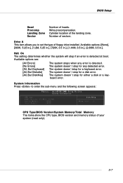
... keyboard error. Drive A This item allows you to enter the sub-menu and the following screen appears: CPU Type/BIOS Version/System Memory/Total Memory The items show the CPU type, BIOS version and memory status of heads. Available options are: [All Errors] [No Errors] [All, But Keyboard] [All..., But Diskette] [All, But Disk/Key] The system stops when any detected error. Cylinder location of sectors. BIOS Setup Head Precomp Landing Zone Sector...
... keyboard error. Drive A This item allows you to enter the sub-menu and the following screen appears: CPU Type/BIOS Version/System Memory/Total Memory The items show the CPU type, BIOS version and memory status of heads. Available options are: [All Errors] [No Errors] [All, But Keyboard] [All..., But Diskette] [All, But Disk/Key] The system stops when any detected error. Cylinder location of sectors. BIOS Setup Head Precomp Landing Zone Sector...
User Guide
Page 49
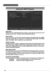
.... Boot To OS/2 This allows you to select which version to enable or disable the APIC (Advanced Programmable Interrupt Controller). MS-7125 ATX Mainboard Advanced BIOS Features Quick Boot Setting the item to [Enabled] allows the system to select the MPS version supported by your operating system.
.... Boot To OS/2 This allows you to select which version to enable or disable the APIC (Advanced Programmable Interrupt Controller). MS-7125 ATX Mainboard Advanced BIOS Features Quick Boot Setting the item to [Enabled] allows the system to select the MPS version supported by your operating system.
User Guide
Page 50
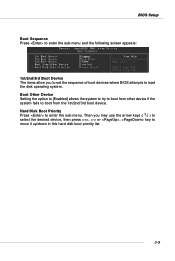
... to boot from the 1st/2nd/3rd boot device. Then you to set the sequence of boot devices where BIOS attempts to move it up/down in this hard disk boot priority list. 3-9 BIOS Setup Boot Sequence Press to enter the sub-menu and the following screen appears: 1st/2nd/3rd Boot...
... to boot from the 1st/2nd/3rd boot device. Then you to set the sequence of boot devices where BIOS attempts to move it up/down in this hard disk boot priority list. 3-9 BIOS Setup Boot Sequence Press to enter the sub-menu and the following screen appears: 1st/2nd/3rd Boot...
User Guide
Page 52
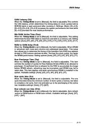
BIOS Setup CAS# Latency (Tcl) When the Timing Mode is set to [Manual], the field is adjustable. If insufficient time is adjustable.This controls the CAS ...
BIOS Setup CAS# Latency (Tcl) When the Timing Mode is set to [Manual], the field is adjustable. If insufficient time is adjustable.This controls the CAS ...
User Guide
Page 54
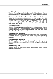
... receiver should be turned on for a read. Setting options: [2ns], [2. 5ns], [3ns], [3.5ns], [4ns], [4.5ns], [5ns], [5.5ns], [6ns], [6.5ns], [7ns], [7.5ns], [8ns], [8.5ns], [9ns], [9.5ns]. BIOS Setup Read Preamble value When the User Config mode is set to [Manual], the field is adjustable. H/W memory hole Remapping This field enables hardware to...
... receiver should be turned on for a read. Setting options: [2ns], [2. 5ns], [3ns], [3.5ns], [4ns], [4.5ns], [5ns], [5.5ns], [6ns], [6.5ns], [7ns], [7.5ns], [8ns], [8.5ns], [9ns], [9.5ns]. BIOS Setup Read Preamble value When the User Config mode is set to [Manual], the field is adjustable. H/W memory hole Remapping This field enables hardware to...


