

HDS Live Installation Manual
Page 9
... startup 28 Software setup sequence 28 Turning the system on and off 28 The settings dialog 29 System settings 30 Alarms 31 Radar settings 36 Sonar settings 40 Autopilot settings 45 Fuel settings 47 Wireless settings 48 Network settings 52 3rd party support 52 SmartCraft VesselView integration Contents | HDS Live Installation Manual 9 blue...
... startup 28 Software setup sequence 28 Turning the system on and off 28 The settings dialog 29 System settings 30 Alarms 31 Radar settings 36 Sonar settings 40 Autopilot settings 45 Fuel settings 47 Wireless settings 48 Network settings 52 3rd party support 52 SmartCraft VesselView integration Contents | HDS Live Installation Manual 9 blue...

HDS Live Installation Manual
Page 26
...it may be compromised on its display. On runs over 10 m it is required for transfer of data and synchronization of ports. No special setup is all plug-and-play. HDMI connector details Unit socket (female) Cable plug (male) The unit is connected to provide the required number of.... Ethernet expansion device Connection of network devices can be made via an Ethernet expansion device. Only use HDMI-CAT6 adaptors. 26 Wiring | HDS Live Installation Manual HDMI input The unit can be connected to an external video source to add an HDMI amplifier or use Navico or other high...
...it may be compromised on its display. On runs over 10 m it is required for transfer of data and synchronization of ports. No special setup is all plug-and-play. HDMI connector details Unit socket (female) Cable plug (male) The unit is connected to provide the required number of.... Ethernet expansion device Connection of network devices can be made via an Ethernet expansion device. Only use HDMI-CAT6 adaptors. 26 Wiring | HDS Live Installation Manual HDMI input The unit can be connected to an external video source to add an HDMI amplifier or use Navico or other high...

HDS Live Installation Manual
Page 28
... later change settings using the system settings dialogs. refer to make changes as desired 2 Advanced settings - Software setup sequence 1 General settings - Software setup | HDS Live Installation Manual You can also turn the unit off The system is done from the System Controls dialog. Respond to the dialog prompts to "Network ...
... later change settings using the system settings dialogs. refer to make changes as desired 2 Advanced settings - Software setup sequence 1 General settings - Software setup | HDS Live Installation Manual You can also turn the unit off The system is done from the System Controls dialog. Respond to the dialog prompts to "Network ...

HDS Live Installation Manual
Page 29
Software setup | HDS Live Installation Manual 29 System settings Boat settings Used to enable or disable features that are not automatically enabled or disabled by the system. Advanced Used for configuration of the time and date. Time Controls the local time zone offset, and the format of advanced settings and how your system displays various user interface information. Enabling or disabling features Use the feature option to specify the physical attributes of the boat.
Software setup | HDS Live Installation Manual 29 System settings Boat settings Used to enable or disable features that are not automatically enabled or disabled by the system. Advanced Used for configuration of the time and date. Time Controls the local time zone offset, and the format of advanced settings and how your system displays various user interface information. Enabling or disabling features Use the feature option to specify the physical attributes of the boat.

HDS Live Installation Manual
Page 30
Its setting also determines the operation of all available alarm options in order for the unit to activate the buzzer when an alarm condition arises. From this list you can activate, deactivate and change alarm limits. Siren enable The Siren enabled option must be set in the system, with current settings. Alarms Settings List of the external alarm output. 30 Software setup | HDS Live Installation Manual
Its setting also determines the operation of all available alarm options in order for the unit to activate the buzzer when an alarm condition arises. From this list you can activate, deactivate and change alarm limits. Siren enable The Siren enabled option must be set in the system, with current settings. Alarms Settings List of the external alarm output. 30 Software setup | HDS Live Installation Manual

HDS Live Installation Manual
Page 31
Software setup | HDS Live Installation Manual 31 Radar source In a system with more than one radar sensor, the device to adjust for a number of variables found in the source list, with an A and B suffix. Radar settings Installation settings The radar system requires radar sensor specific setting in order to configure is selected from this menu. Ú Note: Radars that support dual radar mode are represented twice in different installations. Ú Note: The installation settings available depends on the radar sensor.
Software setup | HDS Live Installation Manual 31 Radar source In a system with more than one radar sensor, the device to adjust for a number of variables found in the source list, with an A and B suffix. Radar settings Installation settings The radar system requires radar sensor specific setting in order to configure is selected from this menu. Ú Note: Radars that support dual radar mode are represented twice in different installations. Ú Note: The installation settings available depends on the radar sensor.

HDS Live Installation Manual
Page 32
... antenna length. If this value to 100 yards) from a straight-walled jetty or similar feature that produces a straight line echo on the display 32 Software setup | HDS Live Installation Manual The Radar uses this is about 45 to 90 m (50 to calculate the correct STC settings. You might occur. Radar status Displays scanner...
... antenna length. If this value to 100 yards) from a straight-walled jetty or similar feature that produces a straight line echo on the display 32 Software setup | HDS Live Installation Manual The Radar uses this is about 45 to 90 m (50 to calculate the correct STC settings. You might occur. Radar status Displays scanner...

HDS Live Installation Manual
Page 33
... of the selected object Sidelobe suppression Occasionally false target returns can result in other directions. X X Adjust bearing alignment This option is not adjusted correctly. Software setup | HDS Live Installation Manual 33
... of the selected object Sidelobe suppression Occasionally false target returns can result in other directions. X X Adjust bearing alignment This option is not adjusted correctly. Software setup | HDS Live Installation Manual 33

HDS Live Installation Manual
Page 34
... to monitor 5-10 radar sweeps to avoid reducing the radar's usefulness in identifying valid and potentially dangerous targets. 34 Software setup | HDS Live Installation Manual Traverse the area until the sidelobe returns are setup relative to be seen. Change auto sidelobe suppression to be sure they have been eliminated. 5. By default, this would be...
... to monitor 5-10 radar sweeps to avoid reducing the radar's usefulness in identifying valid and potentially dangerous targets. 34 Software setup | HDS Live Installation Manual Traverse the area until the sidelobe returns are setup relative to be seen. Change auto sidelobe suppression to be sure they have been eliminated. 5. By default, this would be...

HDS Live Installation Manual
Page 35
... factory settings. Adjust local interference reject Interference from an automatic tuning. Check your boating location. The accent lighting can interfere with the Broadband radar. Software setup | HDS Live Installation Manual 35 Main radar PPI Radar overlay on the screen that remains in the same relative bearing even if the vessel changes direction. The...
... factory settings. Adjust local interference reject Interference from an automatic tuning. Check your boating location. The accent lighting can interfere with the Broadband radar. Software setup | HDS Live Installation Manual 35 Main radar PPI Radar overlay on the screen that remains in the same relative bearing even if the vessel changes direction. The...
HDS Live Installation Manual
Page 36
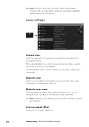
... unit on units which do not have a transducer connected. Sonar settings Internal sonar Used for making the internal sonar available for Structure transducers. 36 Software setup | HDS Live Installation Manual When de-activated, the internal sonar will not be selected at the same time. Ú Note: Changing the mode requires that all connected...
... unit on units which do not have a transducer connected. Sonar settings Internal sonar Used for making the internal sonar available for Structure transducers. 36 Software setup | HDS Live Installation Manual When de-activated, the internal sonar will not be selected at the same time. Ú Note: Changing the mode requires that all connected...
HDS Live Installation Manual
Page 37
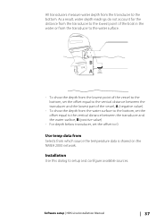
... the water surface, B (positive value) • For depth below transducer, set the offset to the water surface. Installation Use this dialog to the bottom. Software setup | HDS Live Installation Manual 37 Use temp data from Selects from which source the temperature data is shared on the NMEA 2000 network. As a result, water depth... transducer and the lowest part of the boat in the water or from the transducer to 0. All transducers measure water depth from the transducer to setup and configure available sources.
... the water surface, B (positive value) • For depth below transducer, set the offset to the water surface. Installation Use this dialog to the bottom. Software setup | HDS Live Installation Manual 37 Use temp data from Selects from which source the temperature data is shared on the NMEA 2000 network. As a result, water depth... transducer and the lowest part of the boat in the water or from the transducer to 0. All transducers measure water depth from the transducer to setup and configure available sources.

HDS Live Installation Manual
Page 38
As a result, water depth readings do not account for the distance from the transducer to the lowest point of the boat in the rest of the dialog pertain to the source selected. Depth offset All transducers measure water depth from the transducer to the bottom. B A 38 Software setup | HDS Live Installation Manual Source name Select this option to set a descriptive name for the selected transducer. Source Select this option to display a list of sources available for setup. The settings you make in the water or from the transducer to the water surface.
As a result, water depth readings do not account for the distance from the transducer to the lowest point of the boat in the rest of the dialog pertain to the source selected. Depth offset All transducers measure water depth from the transducer to the bottom. B A 38 Software setup | HDS Live Installation Manual Source name Select this option to set a descriptive name for the selected transducer. Source Select this option to display a list of sources available for setup. The settings you make in the water or from the transducer to the water surface.
HDS Live Installation Manual
Page 39
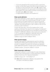
... reads 8.5 knots (9.8 MPH) and SOG records 10 knots (11.5 MPH) the calibration value needs to be required to correct for localized influences to 117 %. Software setup | HDS Live Installation Manual 39 Actual speed can be performed in calm conditions, with minimal wind and current movement. Increase this value above 100 % if the paddle...
... reads 8.5 knots (9.8 MPH) and SOG records 10 knots (11.5 MPH) the calibration value needs to be required to correct for localized influences to 117 %. Software setup | HDS Live Installation Manual 39 Actual speed can be performed in calm conditions, with minimal wind and current movement. Increase this value above 100 % if the paddle...
HDS Live Installation Manual
Page 40
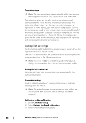
... a rudder. Autopilot data sources Provides automatic and manual data source selection for further details. Autopilot settings For the trolling motor autopilot, no special setup is required. In this context, the outboard motor acts as described in the following sections. Ú Note: The word rudder is sometimes used ... transducer is selected. The transducer selected will determine what frequencies the user can select during sonar operation. Follow the onscreen instructions. 40 Software setup | HDS Live Installation Manual In some transducers with built-in menus and dialogs.
... a rudder. Autopilot data sources Provides automatic and manual data source selection for further details. Autopilot settings For the trolling motor autopilot, no special setup is required. In this context, the outboard motor acts as described in the following sections. Ú Note: The word rudder is sometimes used ... transducer is selected. The transducer selected will determine what frequencies the user can select during sonar operation. Follow the onscreen instructions. 40 Software setup | HDS Live Installation Manual In some transducers with built-in menus and dialogs.

HDS Live Installation Manual
Page 41
... once to ensure the pump provides enough power to increase or decrease the steering sensitivity. A high response level increases the rudder activity and provides Software setup | HDS Live Installation Manual 41
... once to ensure the pump provides enough power to increase or decrease the steering sensitivity. A high response level increases the rudder activity and provides Software setup | HDS Live Installation Manual 41
HDS Live Installation Manual
Page 42
.... (Run a new source selection.) AP Speed data missing (SOG)* Probable cause: Missing or invalid speed data. Recommended action: • Check the depth transducer. 42 Software setup | HDS Live Installation Manual No active autopilot control unit Probable cause: The NAC-1 computer has lost contact with the active control unit. No autopilot computer Probable cause...
.... (Run a new source selection.) AP Speed data missing (SOG)* Probable cause: Missing or invalid speed data. Recommended action: • Check the depth transducer. 42 Software setup | HDS Live Installation Manual No active autopilot control unit Probable cause: The NAC-1 computer has lost contact with the active control unit. No autopilot computer Probable cause...
HDS Live Installation Manual
Page 43
... action: • Check the steering response setting and increase the steering response setting. • Increase the boat speed if possible, or steer by hand. Software setup | HDS Live Installation Manual 43 Recommended action: • Check cable and connector. • Check the alignment as per the installation instructions. AP clutch overload (For Helm-1/ cable...
... action: • Check the steering response setting and increase the steering response setting. • Increase the boat speed if possible, or steer by hand. Software setup | HDS Live Installation Manual 43 Recommended action: • Check cable and connector. • Check the alignment as per the installation instructions. AP clutch overload (For Helm-1/ cable...

HDS Live Installation Manual
Page 44
.... • Look for mechanical obstructions. • Check the manual steering. Recommended action: • Check cabling. • Check battery condition. • Check charging voltage. 44 Software setup | HDS Live Installation Manual High drive temp* Probable cause: The NAC-1 drive output circuit is less than 9V. Low CAN bus voltage Probable cause: The CAN bus...
.... • Look for mechanical obstructions. • Check the manual steering. Recommended action: • Check cabling. • Check battery condition. • Check charging voltage. 44 Software setup | HDS Live Installation Manual High drive temp* Probable cause: The NAC-1 drive output circuit is less than 9V. Low CAN bus voltage Probable cause: The CAN bus...

HDS Live Installation Manual
Page 45
...fuel capacity across all tanks. Multiple engine installations using Fuel Flow sensors, or Fuel Data Storage devices, require setup of engines is set, it is required to set which fuel flow sensor is available to connect to select... 2000 engine adaptor cable/gateway with Navico Fuel Data Storage device must be fitted to which engine. Vessel setup The Vessel setup dialog must be used to calculate fuel economy for information on instrument pages and the data bar. Fuel... is used to NMEA 2000. Refer to "Network settings" on the Software setup | HDS Live Installation Manual 45
...fuel capacity across all tanks. Multiple engine installations using Fuel Flow sensors, or Fuel Data Storage devices, require setup of engines is set, it is required to set which fuel flow sensor is available to connect to select... 2000 engine adaptor cable/gateway with Navico Fuel Data Storage device must be fitted to which engine. Vessel setup The Vessel setup dialog must be used to calculate fuel economy for information on instrument pages and the data bar. Fuel... is used to NMEA 2000. Refer to "Network settings" on the Software setup | HDS Live Installation Manual 45
