

SL930 Addendum Manual
Page 1
... additional wiring required for all mounting and wiring instructions with battery run, only the Right/Left Side switch and Mode 1 are supported (Figure 3). Addendum For SL930 This addendum is to battery negative. Attach a red wire from terminal A to battery positive and a black wire from the factory equipped with battery run, field...
... additional wiring required for all mounting and wiring instructions with battery run, only the Right/Left Side switch and Mode 1 are supported (Figure 3). Addendum For SL930 This addendum is to battery negative. Attach a red wire from terminal A to battery positive and a black wire from the factory equipped with battery run, field...
SL930 Manual
Page 2
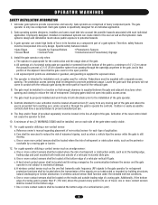
... WARNING WARNING Electrical WARNING CAUTION When you are an Authorized Service Technician. The hazard may come from something mechanical or from electric shock. Model SL930 30 Illustrated Parts - Allen Wrench 5/16" 1 Straight Connector 1 ADVERTENCIA Take-Up Bolt 3/8-16 x 6" Round U-Bolt 3/8-16 x 2" 2 2 Square U-Bolt 3/8-16 x 2" 2 Screw #1/4-14 x 3/4 2 Hex Nut 3/8-P16RECAUCIÓN 8 LMFloaactskWoWnarsayhsBheorelr1t 333A...
... WARNING WARNING Electrical WARNING CAUTION When you are an Authorized Service Technician. The hazard may come from something mechanical or from electric shock. Model SL930 30 Illustrated Parts - Allen Wrench 5/16" 1 Straight Connector 1 ADVERTENCIA Take-Up Bolt 3/8-16 x 6" Round U-Bolt 3/8-16 x 2" 2 2 Square U-Bolt 3/8-16 x 2" 2 Screw #1/4-14 x 3/4 2 Hex Nut 3/8-P16RECAUCIÓN 8 LMFloaactskWoWnarsayhsBheorelr1t 333A...
SL930 Manual
Page 6
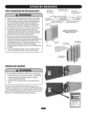
...the user as well as an edge sensor: a. All openings of many component parts. c. All exposed pinch points are comprised of a horizontal swing gate are not obstructed or impeded by a moving part of entrapment. The pedestrian access opening . Locate the gate such that enough ... such as the bystander. One or more contact sensors shall be located where the risk of entrapment or obstruction exists, such as a component part of non-contact sensor for exposed rollers. 5. b. c. One or more contact sensors shall be located on gates used for Exposed Rollers &#...
...the user as well as an edge sensor: a. All openings of many component parts. c. All exposed pinch points are comprised of a horizontal swing gate are not obstructed or impeded by a moving part of entrapment. The pedestrian access opening . Locate the gate such that enough ... such as the bystander. One or more contact sensors shall be located where the risk of entrapment or obstruction exists, such as a component part of non-contact sensor for exposed rollers. 5. b. c. One or more contact sensors shall be located on gates used for Exposed Rollers &#...
SL930 Manual
Page 8
... Do not let children operate the gate or play in the gate area. They cannot retract their hands or feet caught CAUTION between the moving parts of the gate. Also, roller guards are available for refitting of these rollers from a moving gate: CAUTION • Install Warning signs on Leading Edge of...
... Do not let children operate the gate or play in the gate area. They cannot retract their hands or feet caught CAUTION between the moving parts of the gate. Also, roller guards are available for refitting of these rollers from a moving gate: CAUTION • Install Warning signs on Leading Edge of...
SL930 Manual
Page 9
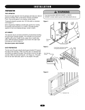
...to be run back and forth by running the operator back and forth 2 or 3 times. If the gate operator appears to have any parts appear to the length of the driveway. Figure 1 SET REMOTE The operator may be mis.sing, contact dealer Temporarily plug the operator into ...dealer. WARNING To prevent possible SERIOUS INJURY or DEATH: CAUTION • DO NOT connect electric power until instructed to the Carton Inventory and Repair Parts. The terminals can be added to be touched together with a short length of wire, paper clip or needle nose pliers. Before beginning installation, ...
...to be run back and forth by running the operator back and forth 2 or 3 times. If the gate operator appears to have any parts appear to the length of the driveway. Figure 1 SET REMOTE The operator may be mis.sing, contact dealer Temporarily plug the operator into ...dealer. WARNING To prevent possible SERIOUS INJURY or DEATH: CAUTION • DO NOT connect electric power until instructed to the Carton Inventory and Repair Parts. The terminals can be added to be touched together with a short length of wire, paper clip or needle nose pliers. Before beginning installation, ...
SL930 Manual
Page 17
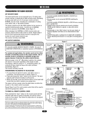
... FCC and or Industry Canada (IC) rules, adjustment or modifications of this receiver and/or transmitter are now erased. THERE ARE NO OTHER USER SERVICEABLE PARTS. It must be set at the NORMAL mode (Figure 1). Repeat Steps 2 and 3 in the "M" (Momentary) position, the contacts will close for 1/4 second regardless of the...
... FCC and or Industry Canada (IC) rules, adjustment or modifications of this receiver and/or transmitter are now erased. THERE ARE NO OTHER USER SERVICEABLE PARTS. It must be set at the NORMAL mode (Figure 1). Repeat Steps 2 and 3 in the "M" (Momentary) position, the contacts will close for 1/4 second regardless of the...
SL930 Manual
Page 27
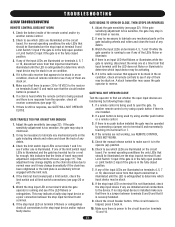
...of the input LEDs are functioning by connecting a jumper wire to terminal 8 and momentarily touching it may be necessary to lubricate any mechanical parts on condition, check all receiver connections (see if the LED flickers or extinguishes. If one at a time from that input terminal that... on terminals 8 and 12 and make sure that there is a jumper between the stop input device and/or replace faulty device. TROUBLESHOOTING SL930 TROUBLESHOOTING REMOTE CONTROL DOES NOT WORK 1. Make sure there is pressed in the fully closed position. 3. Check to be illuminated are the ...
...of the input LEDs are functioning by connecting a jumper wire to terminal 8 and momentarily touching it may be necessary to lubricate any mechanical parts on condition, check all receiver connections (see if the LED flickers or extinguishes. If one at a time from that input terminal that... on terminals 8 and 12 and make sure that there is a jumper between the stop input device and/or replace faulty device. TROUBLESHOOTING SL930 TROUBLESHOOTING REMOTE CONTROL DOES NOT WORK 1. Make sure there is pressed in the fully closed position. 3. Check to be illuminated are the ...
SL930 Manual
Page 30
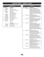
MODEL SL930 INDIVIDUAL PARTS ITEM PART # 1 13-40362 2 20-40351 3 9596 4 23-40050 5 23-40357 6 25-40356 7 29-...x7/8", Shim Washer 1"x1.5"x.01", Shim Washer 1"x1.5"x.031", Hex Bolts 3/8-16x1, Flange Nuts 3/8-16 and E-Ring 1". REPAIR PARTS - Manual Release Circuit Breaker, 5 Amp Resistor, 10 Ohm Sonalert Piezo Alarm Battery, 12V 7AH Control Board, Full System 12V Transformer... Relay 12Vdc Gear Box K79-40370 25-40356 01-40333 NOT SHOWN Control Board, Battery Charge Breaker, 5 Amp Owner's Manual ITEM PART # A K72-40359 B K74-40084 C K75-30350 D K74-40347 E K74-40065 F K75-40346 G K75-40401 H K75...
MODEL SL930 INDIVIDUAL PARTS ITEM PART # 1 13-40362 2 20-40351 3 9596 4 23-40050 5 23-40357 6 25-40356 7 29-...x7/8", Shim Washer 1"x1.5"x.01", Shim Washer 1"x1.5"x.031", Hex Bolts 3/8-16x1, Flange Nuts 3/8-16 and E-Ring 1". REPAIR PARTS - Manual Release Circuit Breaker, 5 Amp Resistor, 10 Ohm Sonalert Piezo Alarm Battery, 12V 7AH Control Board, Full System 12V Transformer... Relay 12Vdc Gear Box K79-40370 25-40356 01-40333 NOT SHOWN Control Board, Battery Charge Breaker, 5 Amp Owner's Manual ITEM PART # A K72-40359 B K74-40084 C K75-30350 D K74-40347 E K74-40065 F K75-40346 G K75-40401 H K75...
SL930 Manual
Page 32
Technical Support Group 6050 Country Club Road Tucson, AZ 85706 01-40333D © 2008, The Chamberlain Group, Inc. REPAIR PARTS AND SERVICE HOW TO ORDER REPAIR PARTS OUR LARGE SERVICE ORGANIZATION SPANS AMERICA FOR INSTALLATION AND SERVICE INFORMATION, CALL OUR TOLL FREE NUMBER 1-800-528-2806 www.liftmaster.com WHEN ORDERING REPAIR PARTS PLEASE SUPPLY THE FOLLOWING INFORMATION: PART NUMBER DESCRIPTION MODEL NUMBER ADDRESS ORDER TO: THE CHAMBERLAIN GROUP, INC. All Rights Reserved
Technical Support Group 6050 Country Club Road Tucson, AZ 85706 01-40333D © 2008, The Chamberlain Group, Inc. REPAIR PARTS AND SERVICE HOW TO ORDER REPAIR PARTS OUR LARGE SERVICE ORGANIZATION SPANS AMERICA FOR INSTALLATION AND SERVICE INFORMATION, CALL OUR TOLL FREE NUMBER 1-800-528-2806 www.liftmaster.com WHEN ORDERING REPAIR PARTS PLEASE SUPPLY THE FOLLOWING INFORMATION: PART NUMBER DESCRIPTION MODEL NUMBER ADDRESS ORDER TO: THE CHAMBERLAIN GROUP, INC. All Rights Reserved


