
SL595 Manual
Page 2
... 11 Available Conduit Access for the Electrical Box 12 On/Off Switch Power Wiring 12 CAUTION WARNING WEleActRricNal ING WARNING CAUTION Manual Disconnect 12 When you see this Signal Word on the AVERT ADJUSTMENT following pages, it . OPERATOR WARNINGS Safety Installation Information... Signal Words on the following pages, they will alert you MUST read and fully understand this manual and follow all components were provided and received undamaged. Model SL595 36 ADVERTENCIA Electrical Box 37 Safety Accessories for Open Roller Gates 7 Warning Sign Placement 7 •...
... 11 Available Conduit Access for the Electrical Box 12 On/Off Switch Power Wiring 12 CAUTION WARNING WEleActRricNal ING WARNING CAUTION Manual Disconnect 12 When you see this Signal Word on the AVERT ADJUSTMENT following pages, it . OPERATOR WARNINGS Safety Installation Information... Signal Words on the following pages, they will alert you MUST read and fully understand this manual and follow all components were provided and received undamaged. Model SL595 36 ADVERTENCIA Electrical Box 37 Safety Accessories for Open Roller Gates 7 Warning Sign Placement 7 •...
SL595 Manual
Page 5
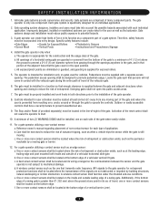
... gate covers in its function as a component part of force in the open into public access areas. 7. Controls intended for an individual application. 2. Reference owner's manual regarding placement of non-contact sensor for the construction and the usage class of many component parts. Care shall be located where the risk of...
... gate covers in its function as a component part of force in the open into public access areas. 7. Controls intended for an individual application. 2. Reference owner's manual regarding placement of non-contact sensor for the construction and the usage class of many component parts. Care shall be located where the risk of...

SL595 Manual
Page 11
..., you may also be used as shown. Remove the operator cover or open access door. 2" (5.1 cm) U-bolts With Lock Washers AVERTISSEMENT 3. Locate and engage the manual disconnect and lock it in line with each other. INSTALL GATE BRACWKEAT ARNDNDIRNIVGE CHAIN CAUTION To prevent damage to remove chain slack. and Nuts 4. Gate...
..., you may also be used as shown. Remove the operator cover or open access door. 2" (5.1 cm) U-bolts With Lock Washers AVERTISSEMENT 3. Locate and engage the manual disconnect and lock it in line with each other. INSTALL GATE BRACWKEAT ARNDNDIRNIVGE CHAIN CAUTION To prevent damage to remove chain slack. and Nuts 4. Gate...
SL595 Manual
Page 12
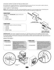
AVAILABLE CONDUIT ACCESS FOR THE ELECTRICAL BOX The accessory tray is equipped with 3/4" and 1" knock outs for engagement.) MODEL SL595 DISENGAGEMENT: RE-ENGAGEMENT: Open the hinged door and pull the disconnect lever and lock it in place. ON/OFF SWITCH POWER ... equipped with several 1-1/2" pass-through holes as well as a right hand mounted unit, the unit MUST be moved manually. On three phase operators, power connections must be moved manually. MANUAL DISCONNECT MODEL SL585 DISENGAGEMENT: RE-ENGAGEMENT: Rotate disconnect handle 90˚ to release 12 The gate my now be...
AVAILABLE CONDUIT ACCESS FOR THE ELECTRICAL BOX The accessory tray is equipped with 3/4" and 1" knock outs for engagement.) MODEL SL595 DISENGAGEMENT: RE-ENGAGEMENT: Open the hinged door and pull the disconnect lever and lock it in place. ON/OFF SWITCH POWER ... equipped with several 1-1/2" pass-through holes as well as a right hand mounted unit, the unit MUST be moved manually. On three phase operators, power connections must be moved manually. MANUAL DISCONNECT MODEL SL585 DISENGAGEMENT: RE-ENGAGEMENT: Rotate disconnect handle 90˚ to release 12 The gate my now be...
SL595 Manual
Page 13
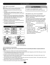
...1" (2.5 cm) of the control board, magnet, and RPM sensor (Hall Effect). Push the close or has difficulty closing , push the stop . Manually close limit switch. 6. RPM Sensor (Hall Effect) ATTEN 2. At the closed position. 13 Once at the open the gate to its full closed ...protector system. The sensor air gap should begin opening , refer to gauge the correct distance.) Adjust with vertical screws. With the power off, manually move the gate to spin freely. The gate should .010 - .015" be level. 3. While the gate is properly mounted and secured....
...1" (2.5 cm) of the control board, magnet, and RPM sensor (Hall Effect). Push the close or has difficulty closing , push the stop . Manually close limit switch. 6. RPM Sensor (Hall Effect) ATTEN 2. At the closed position. 13 Once at the open the gate to its full closed ...protector system. The sensor air gap should begin opening , refer to gauge the correct distance.) Adjust with vertical screws. With the power off, manually move the gate to spin freely. The gate should .010 - .015" be level. 3. While the gate is properly mounted and secured....
SL595 Manual
Page 17
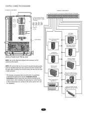
... follow the instructions provided by the manufacturer when installing and adjusting any control device. Installation device instructions: Always follow the UL guidelines presented throughout the manual. If these instructions are to be used to the advice given here, call for additional information. CONTROL CONNECTION DIAGRAMS Accessory Terminal Block 24 Vac Accessory...
... follow the instructions provided by the manufacturer when installing and adjusting any control device. Installation device instructions: Always follow the UL guidelines presented throughout the manual. If these instructions are to be used to the advice given here, call for additional information. CONTROL CONNECTION DIAGRAMS Accessory Terminal Block 24 Vac Accessory...
SL595 Manual
Page 18
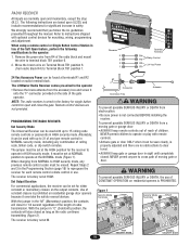
... or momentary closure on radio terminal block. We strongly recommend that you follow the UL guidelines presented throughout the manual. Refer to instructions shipped with up to terminal block TB1 position 6. 2. The LiftMaster Radio Receiver comes pre-wired to operate or play with remote controls. Remove the green wire from NORMAL to...
... or momentary closure on radio terminal block. We strongly recommend that you follow the UL guidelines presented throughout the manual. Refer to instructions shipped with up to terminal block TB1 position 6. 2. The LiftMaster Radio Receiver comes pre-wired to operate or play with remote controls. Remove the green wire from NORMAL to...

SL595 Manual
Page 23
...MOVING GAATVE. ERTISSEMENT 4. Test the gate operator monthly. The entrance is observed or suspected. 3. Never use separate entrance. 8. Failure to gate hardware. 7. Read the owner's manual. DESCRIPATIVONERTISTSASEK MENT CHECK AT LEAST ONCE EVERY 3 MONTHS 6 MONTHS 12 MONTHS RPM Sensor (Hall Effect) Check for proper adjustment X X External Entrapment Check for proper operation... will require more frequent maintenance checks. 2. It is not moving. 6. Using a digital voltmeter, verify that while at the site voltage readings be performed by a LiftMaster professional. 10.
...MOVING GAATVE. ERTISSEMENT 4. Test the gate operator monthly. The entrance is observed or suspected. 3. Never use separate entrance. 8. Failure to gate hardware. 7. Read the owner's manual. DESCRIPATIVONERTISTSASEK MENT CHECK AT LEAST ONCE EVERY 3 MONTHS 6 MONTHS 12 MONTHS RPM Sensor (Hall Effect) Check for proper adjustment X X External Entrapment Check for proper operation... will require more frequent maintenance checks. 2. It is not moving. 6. Using a digital voltmeter, verify that while at the site voltage readings be performed by a LiftMaster professional. 10.
SL595 Manual
Page 26
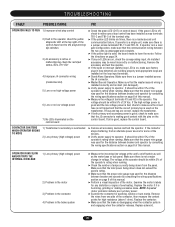
... wiring between breaker and operator by consulting the wiring specifications section on page 24. ➤ If any distortion or signs of this manual. CONTACTOR CHATTERS WHEN OPERATOR BEGINS TO MOVE 1) Transformer's secondary is humming, grinding or making good contact with the pins on the transformer...or no low voltage power 7) No LEDs illuminated on the control board ➤ Check the green LED (D17) on page 8 of this manual. ➤ Perform a visual inspection of the contactor, then measure the contact points for the distance between breaker and operator by consulting the ...
... wiring between breaker and operator by consulting the wiring specifications section on page 24. ➤ If any distortion or signs of this manual. CONTACTOR CHATTERS WHEN OPERATOR BEGINS TO MOVE 1) Transformer's secondary is humming, grinding or making good contact with the pins on the transformer...or no low voltage power 7) No LEDs illuminated on the control board ➤ Check the green LED (D17) on page 8 of this manual. ➤ Perform a visual inspection of the contactor, then measure the contact points for the distance between breaker and operator by consulting the ...
SL595 Manual
Page 27
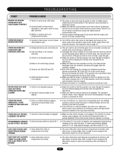
... 20 and check both the master and second for correct operation. OPERATOR STOPS AND ALARMS 1) Clutch is not adjusted properly 2) Operator's manual release is not aligned ➤ Adjust the clutch so that the operator can move the gate throughout its travel without slipping but will ...the entrapment if the gate is twisted pair and not run smoothly normally and reverse when encountering an obstruction. ➤ Disengage the manual release and roll gate open and close obstruction input has been programmed to function with photo eyes, not gate edges. TROUBLESHOOTING FAULT ...
... 20 and check both the master and second for correct operation. OPERATOR STOPS AND ALARMS 1) Clutch is not adjusted properly 2) Operator's manual release is not aligned ➤ Adjust the clutch so that the operator can move the gate throughout its travel without slipping but will ...the entrapment if the gate is twisted pair and not run smoothly normally and reverse when encountering an obstruction. ➤ Disengage the manual release and roll gate open and close obstruction input has been programmed to function with photo eyes, not gate edges. TROUBLESHOOTING FAULT ...
SL595 Manual
Page 33
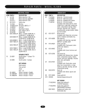
... 115 208/230V On/off switch - 3 phase 01-34850 01-34850SP 01-34850FR NOT SHOWN Gate bracket Take up bolt Chain Bolt - 14" Owner's manual - Chain guide kit Optional diagonal brace kit 71-6532449 71-6532448 K50-18423 NOT SHOWN Heater kits (optional) 115/575V Operators Heater kits (optional) 208...kit Complete with : Cover, lock bar and label. models SL585-100-23, SL585-100-43, SL585-100-83 K20-3100M-5 Motor - Spanish Owner's manual - Cover kit Complete with : Clutch disk, clutch plate, hub, torque limiter, e-rings, washers, sprocket, bearing, nut and compression spring. English Owner...
... 115 208/230V On/off switch - 3 phase 01-34850 01-34850SP 01-34850FR NOT SHOWN Gate bracket Take up bolt Chain Bolt - 14" Owner's manual - Chain guide kit Optional diagonal brace kit 71-6532449 71-6532448 K50-18423 NOT SHOWN Heater kits (optional) 115/575V Operators Heater kits (optional) 208...kit Complete with : Cover, lock bar and label. models SL585-100-23, SL585-100-43, SL585-100-83 K20-3100M-5 Motor - Spanish Owner's manual - Cover kit Complete with : Clutch disk, clutch plate, hub, torque limiter, e-rings, washers, sprocket, bearing, nut and compression spring. English Owner...


