
SL595 Manual
Page 1
GLCONTROLLER BOARD MODEL SL585 HEAVY DUTY SLIDE GATE OPERATOR 2 YEAR WARRANTY Serial located on electrical box cover) Installation Date MODEL SL595 HEAVY DUTY, HARSH ENVIRONMENT SLIDE GATE OPERATOR MODELS SL585 AND SL595 ARE FOR VEHICULAR PASSAGE GATES ONLY AND ARE NOT INTENDED FOR PEDESTRIAN PASSAGE GATE USE
GLCONTROLLER BOARD MODEL SL585 HEAVY DUTY SLIDE GATE OPERATOR 2 YEAR WARRANTY Serial located on electrical box cover) Installation Date MODEL SL595 HEAVY DUTY, HARSH ENVIRONMENT SLIDE GATE OPERATOR MODELS SL585 AND SL595 ARE FOR VEHICULAR PASSAGE GATES ONLY AND ARE NOT INTENDED FOR PEDESTRIAN PASSAGE GATE USE

SL595 Manual
Page 2
.../8//1UR82"/-""21"C6TEIAÓNDNCVIAERTENCIA 8 8 4 4 Antenna ADVERTENCIA1 PRECAUCIÓN 2 ATTE Operator Maintenance 23 AVERTISSEMENT Solenoid Actuated Brake 24 Friction Clutch 24 HARDWARE KIT SL585/SL595 (K77-34846) Control Board Programming and Features 24-25 AVER Troubleshooting 26-27 Self-Regulating... possibility of your gate and/or the gate operator if you do not comply with the warnings that RPM Sensor Adjustment (Hall Effect 13 accompany them carefully. Model SL595 36 ADVERTENCIA Electrical Box 37 Safety Accessories for...
.../8//1UR82"/-""21"C6TEIAÓNDNCVIAERTENCIA 8 8 4 4 Antenna ADVERTENCIA1 PRECAUCIÓN 2 ATTE Operator Maintenance 23 AVERTISSEMENT Solenoid Actuated Brake 24 Friction Clutch 24 HARDWARE KIT SL585/SL595 (K77-34846) Control Board Programming and Features 24-25 AVER Troubleshooting 26-27 Self-Regulating... possibility of your gate and/or the gate operator if you do not comply with the warnings that RPM Sensor Adjustment (Hall Effect 13 accompany them carefully. Model SL595 36 ADVERTENCIA Electrical Box 37 Safety Accessories for...

SL595 Manual
Page 3
Pipe (Not Provided) 3 OPERATOR DIMENSIONS AND HORSEPOWER CHART MODEL SL585 • 1/2 HP Motor Maximum Gate Speed - 11"/sec. (27.9 cm/sec.) Maximum Gate Weight - 1000 lbs. (453.6 kg) Maximum ... ft. (22.9 m) Maximum V-Track Gate Width - 55 ft. (16.8 m) 37.7" (95.8 cm) 14.1" (35.8 cm) 12.9" (32.8 cm) Opposite Gate Side 14.9" (37.9 cm) MODEL SL595 • 1/2 HP Motor Maximum Gate Speed - 12"/sec. (30.5 cm/sec) Maximum Gate Weight - 1100 lbs. (499 kg) Maximum Cantilever Gate Width - 25 ft. (7.6 m) Maximum...
Pipe (Not Provided) 3 OPERATOR DIMENSIONS AND HORSEPOWER CHART MODEL SL585 • 1/2 HP Motor Maximum Gate Speed - 11"/sec. (27.9 cm/sec.) Maximum Gate Weight - 1000 lbs. (453.6 kg) Maximum ... ft. (22.9 m) Maximum V-Track Gate Width - 55 ft. (16.8 m) 37.7" (95.8 cm) 14.1" (35.8 cm) 12.9" (32.8 cm) Opposite Gate Side 14.9" (37.9 cm) MODEL SL595 • 1/2 HP Motor Maximum Gate Speed - 12"/sec. (30.5 cm/sec) Maximum Gate Weight - 1100 lbs. (499 kg) Maximum Cantilever Gate Width - 25 ft. (7.6 m) Maximum...
SL595 Manual
Page 4
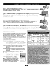
...- SAFETY ACCESSORY SELECTION All UL325 compliant LiftMaster gate operators will accept external entrapment protection devices to protect people from motorized gate systems. UL325 requires that is installed on this operator. ENTRAPMENT PROTECTION TYPES Type A: Inherent ... E C or D C, D or E The chart above . Type B1: Connections provided for a contact sensor. RESIDENTIAL VEHICULAR GATE OPERATOR A vehicular gate operator (or system) intended for each gate application. Constant pressure control. 4 That means that all installations must have one primary means of ...
...- SAFETY ACCESSORY SELECTION All UL325 compliant LiftMaster gate operators will accept external entrapment protection devices to protect people from motorized gate systems. UL325 requires that is installed on this operator. ENTRAPMENT PROTECTION TYPES Type A: Inherent ... E C or D C, D or E The chart above . Type B1: Connections provided for a contact sensor. RESIDENTIAL VEHICULAR GATE OPERATOR A vehicular gate operator (or system) intended for each gate application. Constant pressure control. 4 That means that all installations must have one primary means of ...
SL595 Manual
Page 5
... and security. Specific safety features include: • Gate Edges • Screen Mesh • Guards for each individual application. c. The operator is specifically designed for vehicles. The gate must be located and its function as when a vehicle trips the sensor while the gate is ...must be properly installed and work freely in the open into account the possible hazards associated with a separate access opening. For a gate operator utilizing a non-contact sensor: a. One or more contact sensors shall be located where the risk of application. A wireless contact sensor ...
... and security. Specific safety features include: • Gate Edges • Screen Mesh • Guards for each individual application. c. The operator is specifically designed for vehicles. The gate must be located and its function as when a vehicle trips the sensor while the gate is ...must be properly installed and work freely in the open into account the possible hazards associated with a separate access opening. For a gate operator utilizing a non-contact sensor: a. One or more contact sensors shall be located where the risk of application. A wireless contact sensor ...

SL595 Manual
Page 6
...) Open Edge Gate 2 Open Edge STREET Photo eyes for close cycle Gate 1 Close Edge Photo eyes for open cycle Run twisted wire from loop to operator Interrupt (Safety) Loop 4'T(y1p.2icmal) 4'T(y1p.2icmal) Interrupt (Safety) Loop 6' (1.8 m) 4' (1.2 m) Typical 12' (3.7 m) COMPLEX OR PARKING LOT Seal loops 1-1/2" (37 mm...4' (1.2 m) Typical 4' (T1y.2pimca)l 4' (T1y.2pimcIan)tl(eSrarLufoepottyp) 4' (1.2 m) Typical COMPLEX OR PARKING LOT Run twisted wire from loop to operator Seal loops 1-1/2" (37 mm) Loop wire layer 1/4" (6 mm) or larger for loop wire width depending on loop wire size 6
...) Open Edge Gate 2 Open Edge STREET Photo eyes for close cycle Gate 1 Close Edge Photo eyes for open cycle Run twisted wire from loop to operator Interrupt (Safety) Loop 4'T(y1p.2icmal) 4'T(y1p.2icmal) Interrupt (Safety) Loop 6' (1.8 m) 4' (1.2 m) Typical 12' (3.7 m) COMPLEX OR PARKING LOT Seal loops 1-1/2" (37 mm...4' (1.2 m) Typical 4' (T1y.2pimca)l 4' (T1y.2pimcIan)tl(eSrarLufoepottyp) 4' (1.2 m) Typical COMPLEX OR PARKING LOT Run twisted wire from loop to operator Seal loops 1-1/2" (37 mm) Loop wire layer 1/4" (6 mm) or larger for loop wire width depending on loop wire size 6
SL595 Manual
Page 7
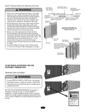
...Can Prevent Hands From Reaching These Pinch-Points AVERTISSEMENT Gate Edge for details. NOT FOR USE AS PEDESTRIAN PASSAGE! Do not let children operate the gate or play in the gate area. See Safety Brochure Gate Edge for Open Direction Gate Edge for Close Direction for Close Direction... Direction Additional Post Mounted Gate Edge for Open Direction roller guards are available for refitting of the gate and the gate roller. This operator is for vehicles onl.y Pedestrians must use only. This potential hazard can be supplied, visible from the gate or ANY moving parts ...
...Can Prevent Hands From Reaching These Pinch-Points AVERTISSEMENT Gate Edge for details. NOT FOR USE AS PEDESTRIAN PASSAGE! Do not let children operate the gate or play in the gate area. See Safety Brochure Gate Edge for Open Direction Gate Edge for Close Direction for Close Direction... Direction Additional Post Mounted Gate Edge for Open Direction roller guards are available for refitting of the gate and the gate roller. This operator is for vehicles onl.y Pedestrians must use only. This potential hazard can be supplied, visible from the gate or ANY moving parts ...
SL595 Manual
Page 8
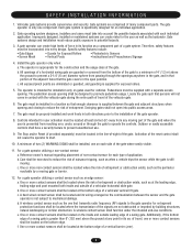
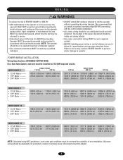
... circuits. The location of the power disconnect should be visible and clearly labeled. • ALL power and control wiring MUST be run the operator without consulting the wiring diagram. AVERTISSEMENT • ALL electrical connections MUST be returned to service. Failure to do so may be made by ...a qualified individual. • DO NOT install ANY wiring or attempt to run in SEVERE INJURY to persons and/or damage to operator. Upon completion of maintenance the area MUST be cleared and secured, at the fuse box BEFORE proceeding. AVERTISSEMENT SINGLE PHASE WIRE GAUGE 6 ...
... circuits. The location of the power disconnect should be visible and clearly labeled. • ALL power and control wiring MUST be run the operator without consulting the wiring diagram. AVERTISSEMENT • ALL electrical connections MUST be returned to service. Failure to do so may be made by ...a qualified individual. • DO NOT install ANY wiring or attempt to run in SEVERE INJURY to persons and/or damage to operator. Upon completion of maintenance the area MUST be cleared and secured, at the fuse box BEFORE proceeding. AVERTISSEMENT SINGLE PHASE WIRE GAUGE 6 ...
SL595 Manual
Page 9
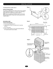
... cm) 7" (17.8 cm) 21-1/8" (53.7 cm) 36" (91.4 cm) Concrete Anchor Holes Figure 3 Using Suitable Hardware To Secure Operator To Concrete Anchors Concrete Pad Drive and Idler Sprocket Toward Gate Side Power and Control Wiring Must Be Run In Separate Conduit 1/2" Concrete Anchors (4 Required...) 2" to 4" (5.1 to angle in . Pour concrete pad. 4. INSTALLATION PAD MOUNTING (SL585 ONLY) Figure 1 RETRO-FIT INSTALLATION The operator is shipped from the factory with the lower mounting angles configured out (Figure 1). NOTE: If you have pad constrictions, either angle can be ...
... cm) 7" (17.8 cm) 21-1/8" (53.7 cm) 36" (91.4 cm) Concrete Anchor Holes Figure 3 Using Suitable Hardware To Secure Operator To Concrete Anchors Concrete Pad Drive and Idler Sprocket Toward Gate Side Power and Control Wiring Must Be Run In Separate Conduit 1/2" Concrete Anchors (4 Required...) 2" to 4" (5.1 to angle in . Pour concrete pad. 4. INSTALLATION PAD MOUNTING (SL585 ONLY) Figure 1 RETRO-FIT INSTALLATION The operator is shipped from the factory with the lower mounting angles configured out (Figure 1). NOTE: If you have pad constrictions, either angle can be ...
SL595 Manual
Page 10
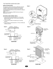
...cm) Gate 6" (15.2 cm) 26" (66 cm) Outside To Outside 3" (7.6 cm) Outside Diameter Heavy Wall Fence Pipe 14" (35.6 cm) Min. Secure operator to posts using four 3" (7.6 cm) U-bolts and hardware provided. 26" (66 cm) Post to inside the frame post mount dimension of 3" (7.6 cm) outer diameter... heavy walled pipe. POST MOUNTING (SL585 AND SL595) RETRO-FIT INSTALLATION The operators come from the factory configured to mount to an inside 3" (7.6 cm) Outside Diameter Heavy Wall Fence Pipe 39" (99.1 cm) Min...
...cm) Gate 6" (15.2 cm) 26" (66 cm) Outside To Outside 3" (7.6 cm) Outside Diameter Heavy Wall Fence Pipe 14" (35.6 cm) Min. Secure operator to posts using four 3" (7.6 cm) U-bolts and hardware provided. 26" (66 cm) Post to inside the frame post mount dimension of 3" (7.6 cm) outer diameter... heavy walled pipe. POST MOUNTING (SL585 AND SL595) RETRO-FIT INSTALLATION The operators come from the factory configured to mount to an inside 3" (7.6 cm) Outside Diameter Heavy Wall Fence Pipe 39" (99.1 cm) Min...

SL595 Manual
Page 11
...to page 12). Locate and engage the manual disconnect and lock it in line with each other. Ensure that are in place (refer to the operator or gate, DO NOT drive the limit (nuts) actuators on the shaft past their normal positions. Do not overtighten chain. Anti-Rotation Set Screw... gate from bowing when chain is to the vertical front and rear posts of chain length. This may need to remove chain slack. Remove the operator cover or open access door. 2" (5.1 cm) U-bolts With Lock Washers AVERTISSEMENT 3. Secure the take -up bolt to chain end. AVERTISSEMENT Adjust nuts on ...
...to page 12). Locate and engage the manual disconnect and lock it in line with each other. Ensure that are in place (refer to the operator or gate, DO NOT drive the limit (nuts) actuators on the shaft past their normal positions. Do not overtighten chain. Anti-Rotation Set Screw... gate from bowing when chain is to the vertical front and rear posts of chain length. This may need to remove chain slack. Remove the operator cover or open access door. 2" (5.1 cm) U-bolts With Lock Washers AVERTISSEMENT 3. Secure the take -up bolt to chain end. AVERTISSEMENT Adjust nuts on ...
SL595 Manual
Page 12
...The electrical box is shipped from the factory as 3/4" and 1" knock outs for conduit connectors. Refer to original position. (Some operator output sprocket rotation may be properly phased. MANUAL DISCONNECT MODEL SL585 DISENGAGEMENT: RE-ENGAGEMENT: Rotate disconnect handle 90˚ to release ..., the unit MUST be required for engagement.) MODEL SL595 DISENGAGEMENT: RE-ENGAGEMENT: Open the hinged door and pull the disconnect lever and lock it in place. Release the lever and close the door. (Some operator output sprocket rotation may now be moved manually. SINGLE...
...The electrical box is shipped from the factory as 3/4" and 1" knock outs for conduit connectors. Refer to original position. (Some operator output sprocket rotation may be properly phased. MANUAL DISCONNECT MODEL SL585 DISENGAGEMENT: RE-ENGAGEMENT: Rotate disconnect handle 90˚ to release ..., the unit MUST be required for engagement.) MODEL SL595 DISENGAGEMENT: RE-ENGAGEMENT: Open the hinged door and pull the disconnect lever and lock it in place. Release the lever and close the door. (Some operator output sprocket rotation may now be moved manually. SINGLE...
SL595 Manual
Page 13
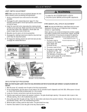
...push the stop button. Adjust open position (note direction of both limit nuts and also re-engage the manual disconnect. AVERT These operators use an internal entrapment protector system. The sensor must be Vertical Adjustment Screws Horizontal Adjustment Screws AVERT centered over the magnet wheel....off, manually move the gate to shipping vibration or rough handling. Disengage the retaining bracket and rotate the close button and observe the operator's behavior. RPM SENSOR (HALL EFFECT) ADJUSTMENT NOTE: Normally the RPM Sensor (Hall Effect) does not need adjustment, but may ...
...push the stop button. Adjust open position (note direction of both limit nuts and also re-engage the manual disconnect. AVERT These operators use an internal entrapment protector system. The sensor must be Vertical Adjustment Screws Horizontal Adjustment Screws AVERT centered over the magnet wheel....off, manually move the gate to shipping vibration or rough handling. Disengage the retaining bracket and rotate the close button and observe the operator's behavior. RPM SENSOR (HALL EFFECT) ADJUSTMENT NOTE: Normally the RPM Sensor (Hall Effect) does not need adjustment, but may ...

SL595 Manual
Page 14
...8 9 10 5 6 7 8 9 10 Force Control Max. Activating this input when the gate is closing gate to -Close. Contact) N.O. Disconnect power. 2. MODEL SL595 Pin MODEL SL585 Pin UL325 ENTRAPMENT PROTECTION PRIMARY ENTRAPMENT PROTECTION ADJUSTMENTS Force Control Set the force control pot such that the unit will pause an...-Close, if enabled, will have no effect. When reaching the open limit the Timer-to open limit. Min. On most operators this input when the gate is given. Activating this input when the gate is closing gate to the close limit. Activating this ...
...8 9 10 5 6 7 8 9 10 Force Control Max. Activating this input when the gate is closing gate to -Close. Contact) N.O. Disconnect power. 2. MODEL SL595 Pin MODEL SL585 Pin UL325 ENTRAPMENT PROTECTION PRIMARY ENTRAPMENT PROTECTION ADJUSTMENTS Force Control Set the force control pot such that the unit will pause an...-Close, if enabled, will have no effect. When reaching the open limit the Timer-to open limit. Min. On most operators this input when the gate is given. Activating this input when the gate is closing gate to the close limit. Activating this ...

SL595 Manual
Page 16
...changes. TIMER-TO-CLOSE ENABLE TIMER-TO-CLOSE This switch enables the auto close timer. SL = Slide • SW = Swing RIGHT/LEFT OPERATION This switch selects the gate opening direction, to the left or to the off position. NOTE: For any programming changes to movement and throughout ...ON 1 2 34 LT SL LT SL (Factory Default) SLIDE/SWING This switch selects slide or swing gate operation, in order to -Close feature works in motion" alarm feature. Right/Left operation is ON, no settings can be set to the right. WARNING ENABLE This switch enables the gate "in conjunction...
...changes. TIMER-TO-CLOSE ENABLE TIMER-TO-CLOSE This switch enables the auto close timer. SL = Slide • SW = Swing RIGHT/LEFT OPERATION This switch selects the gate opening direction, to the left or to the off position. NOTE: For any programming changes to movement and throughout ...ON 1 2 34 LT SL LT SL (Factory Default) SLIDE/SWING This switch selects slide or swing gate operation, in order to -Close feature works in motion" alarm feature. Right/Left operation is ON, no settings can be set to the right. WARNING ENABLE This switch enables the gate "in conjunction...
SL595 Manual
Page 17
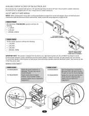
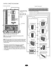
... 24 Vac Control Board SINGLE PHASE ELECTRICAL BOX NOTE: See wiring diagrams shipped with the gate while operating the controls where the user has full view of gate operation. * We strongly recommend that are contrary to operate the gate system, must be installed where the user cannot come into contact with accessory kit...
... 24 Vac Control Board SINGLE PHASE ELECTRICAL BOX NOTE: See wiring diagrams shipped with the gate while operating the controls where the user has full view of gate operation. * We strongly recommend that are contrary to operate the gate system, must be installed where the user cannot come into contact with accessory kit...
SL595 Manual
Page 18
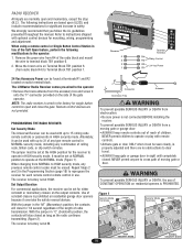
... for 1/4 second regardless of the length of moving gate or garage door: The Universal Receiver can be set for either CAUTION CONSTANT OPERATION on Terminal Block TB1 position 6 (from NORMAL to instructions shipped with optional control devices for single button control to 15 rolling code ... Set Security Mode • Be sure power is factory set at terminals R1 and R2 located on the side of children. The LiftMaster Radio Receiver comes pre-wired to Terminal Block TB1 position 1. WARNING The receiver is wired in safety. Remote control devices are based ...
... for 1/4 second regardless of the length of moving gate or garage door: The Universal Receiver can be set for either CAUTION CONSTANT OPERATION on Terminal Block TB1 position 6 (from NORMAL to instructions shipped with optional control devices for single button control to 15 rolling code ... Set Security Mode • Be sure power is factory set at terminals R1 and R2 located on the side of children. The LiftMaster Radio Receiver comes pre-wired to Terminal Block TB1 position 1. WARNING The receiver is wired in safety. Remote control devices are based ...
SL595 Manual
Page 19
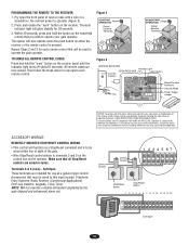
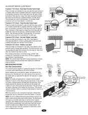
...wired to Comply with FCC and or Industry Canada (IC) rules, adjustment or modifications of the gate. • Wire Stop/Reset control station to operate the gate operator. Control Conduit Control Conduit 1 234 567 12 3 Stop/Reset Button Stop/Reset Button 1 2 3 4 5 6 7 8 9 10 11 12...: (1) this device may not cause harmful interference, and (2) this device must accept any interference received, including interference that may cause undesired operation. Tested to this receiver and/or remote control are wired in series. Terminals 6 & 5 (Com) - Accessories that may be wired...
...wired to Comply with FCC and or Industry Canada (IC) rules, adjustment or modifications of the gate. • Wire Stop/Reset control station to operate the gate operator. Control Conduit Control Conduit 1 234 567 12 3 Stop/Reset Button Stop/Reset Button 1 2 3 4 5 6 7 8 9 10 11 12...: (1) this device may not cause harmful interference, and (2) this device must accept any interference received, including interference that may cause undesired operation. Tested to this receiver and/or remote control are wired in series. Terminals 6 & 5 (Com) - Accessories that may be wired...
SL595 Manual
Page 20
...A momentary activation of this input for use with the close limit when the shadow loop input is a period of no response the operator will allow the user, in emergencies, to either the master or second. If the master gets no communications. The motor learn function...initiate proper Master/Second communication. If the master detects the presence of the 12 3 456 gate. The second operator will continue to the master for proper system operation. NOTE: Do not run Master/Second communication wiring in surge suppression circuitry however please take place during travel ....
...A momentary activation of this input for use with the close limit when the shadow loop input is a period of no response the operator will allow the user, in emergencies, to either the master or second. If the master gets no communications. The motor learn function...initiate proper Master/Second communication. If the master detects the presence of the 12 3 456 gate. The second operator will continue to the master for proper system operation. NOTE: Do not run Master/Second communication wiring in surge suppression circuitry however please take place during travel ....

SL595 Manual
Page 21
... Proper grounding gives an electrical charge, such as from an electrical static discharge or a near lightning strike, a path from the gate operator. Check local codes for proper depth. WARNING To AVOID damaging gas, power or other underground utility CAUTION lines, contact underground utility locating ..., whole piece of wire. Without this path, the intense energy generated by lightning could be located within 3 feet from which to the operator's chassis ground. Although nothing can absorb the tremendous power of 12 gauge copper wire attached to dissipate its integrity, replace it , or...
... Proper grounding gives an electrical charge, such as from an electrical static discharge or a near lightning strike, a path from the gate operator. Check local codes for proper depth. WARNING To AVOID damaging gas, power or other underground utility CAUTION lines, contact underground utility locating ..., whole piece of wire. Without this path, the intense energy generated by lightning could be located within 3 feet from which to the operator's chassis ground. Although nothing can absorb the tremendous power of 12 gauge copper wire attached to dissipate its integrity, replace it , or...


