SL595 Manual
Page 18
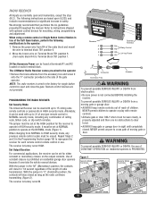
... ATTENTION When changing from NORMAL to operate or play with optional control devices for single button control to Terminal Block TB1 position 1. NORMAL security mode, including any previous remote control codes must be seen clearly, is not connected BEFORE installing the receiver. The LiftMaster Radio Receiver comes pre-wired to operate at terminals R1 and...
... ATTENTION When changing from NORMAL to operate or play with optional control devices for single button control to Terminal Block TB1 position 1. NORMAL security mode, including any previous remote control codes must be seen clearly, is not connected BEFORE installing the receiver. The LiftMaster Radio Receiver comes pre-wired to operate at terminals R1 and...
SL595 Manual
Page 19
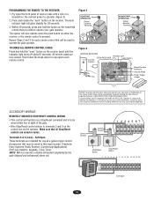
... Power Supply Jumper NOTICE: To comply with FCC and or Industry Canada (IC) rules, adjustment or modifications of this receiver and/or remote control are wired in series. NOTE: Will not override a double entrapment (signalled by the gate stopped and entrapment alarm on the receiver.... Telephone Entry Systems, Radio Receiver (Commercial Applications), Exit Loop Detector, Keypads, 7-Day Timer. TO ERASE ALL REMOTE CONTROL CODES Press and hold the button on the hand-held remote that may cause undesired operation. Make sure that may be wired within line of sight of receiver case with...
... Power Supply Jumper NOTICE: To comply with FCC and or Industry Canada (IC) rules, adjustment or modifications of this receiver and/or remote control are wired in series. NOTE: Will not override a double entrapment (signalled by the gate stopped and entrapment alarm on the receiver.... Telephone Entry Systems, Radio Receiver (Commercial Applications), Exit Loop Detector, Keypads, 7-Day Timer. TO ERASE ALL REMOTE CONTROL CODES Press and hold the button on the hand-held remote that may cause undesired operation. Make sure that may be wired within line of sight of receiver case with...

SL595 Manual
Page 23
... AND MAINTENANCE NG N IMPORTANT SAWFAERTYNIINNGSTRUCTIONS WARNING To reduce the risk of the operator and the area around the operator. Keep the remote control away from the gate. ALWAYS keep people and objects away from children. 3. Test the gate operator monthly. After adjusting the ...gate hardware. 7. SAVE THESE INSTRUCTIONS. Never use separate entrance. 8. It is suggested that the incoming voltage to be performed by a LiftMaster professional. 10. Have a qualified service person make repairs to adjust and retest the gate operator properly can increase the risk of travel, ...
... AND MAINTENANCE NG N IMPORTANT SAWFAERTYNIINNGSTRUCTIONS WARNING To reduce the risk of the operator and the area around the operator. Keep the remote control away from the gate. ALWAYS keep people and objects away from children. 3. Test the gate operator monthly. After adjusting the ...gate hardware. 7. SAVE THESE INSTRUCTIONS. Never use separate entrance. 8. It is suggested that the incoming voltage to be performed by a LiftMaster professional. 10. Have a qualified service person make repairs to adjust and retest the gate operator properly can increase the risk of travel, ...
SL595 Manual
Page 29
... ONLY). Outlet wiring: Black wire to brass screw, white wire to silver screw and green wire to the operator: 1. When using a remote control or Single Button Control Station in lieu of the Soft Open feature, perform the following modifications to green screw. 5. Fuse: 3AG, 3.2A, 120V, SLO-BLO...) (SL595 WH) 83 (BK) 52 (BK) 230V BRAKE SOLENOID (GY) (SL595 GN) 1 (BL/BK) TO REVERSE MOTOR DIRECTION INTERCHANGE PURPLE & GRAY WIRES ON MODEL SL585 OR THE RED & GREEN WIRES ON MODEL SL595 INTERNAL MOTOR WIRING 1 - BLACK 8 - LOOP J1-8 (Y/BK) (BRN) (OR) (GN) (Y/BK) STOP RESET (Y/BK...
... ONLY). Outlet wiring: Black wire to brass screw, white wire to silver screw and green wire to the operator: 1. When using a remote control or Single Button Control Station in lieu of the Soft Open feature, perform the following modifications to green screw. 5. Fuse: 3AG, 3.2A, 120V, SLO-BLO...) (SL595 WH) 83 (BK) 52 (BK) 230V BRAKE SOLENOID (GY) (SL595 GN) 1 (BL/BK) TO REVERSE MOTOR DIRECTION INTERCHANGE PURPLE & GRAY WIRES ON MODEL SL585 OR THE RED & GREEN WIRES ON MODEL SL595 INTERNAL MOTOR WIRING 1 - BLACK 8 - LOOP J1-8 (Y/BK) (BRN) (OR) (GN) (Y/BK) STOP RESET (Y/BK...
SL595 Manual
Page 30
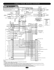
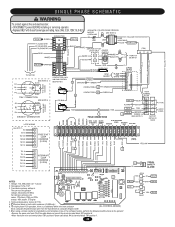
CONNECTION 230V. Horsepower 1/2 & 1 HP. 3. Transformer primary voltage is an additional white wire from contactor (GL CONTROL BOARD) A2 to contactor B4 and the black wire from radio block R4) to terminal block TB1 position 1. 30 R2 BK RD OPEN Y/BK OR ...: 3AG, 3.2A, 120V, SLO-BLO A1 A2 13 14 5 6 3 4 1 2 (TB2) L1 POWER IN L2 SEE NOTE 1 115V. Voltage: 115, 208 & 230 volt - 1 phase. 2. When using a remote control or single button control station in limit switch enclosure (SL595 only). 6. Secondary 24v/60va.
CONNECTION 230V. Horsepower 1/2 & 1 HP. 3. Transformer primary voltage is an additional white wire from contactor (GL CONTROL BOARD) A2 to contactor B4 and the black wire from radio block R4) to terminal block TB1 position 1. 30 R2 BK RD OPEN Y/BK OR ...: 3AG, 3.2A, 120V, SLO-BLO A1 A2 13 14 5 6 3 4 1 2 (TB2) L1 POWER IN L2 SEE NOTE 1 115V. Voltage: 115, 208 & 230 volt - 1 phase. 2. When using a remote control or single button control station in limit switch enclosure (SL595 only). 6. Secondary 24v/60va.

SL595 Manual
Page 31
OPEN OBS. Three phase units are equipped with fuse of same type and rating. When using a remote control or Single Button Control Station in lieu of the radio block and mount the wire to terminal block TB1 position 6. 2. Move the brown wire on Terminal Block TB1 position 6... (BRN) SAFETY ALARM (100 db) - (BK) + (RD) (SEE NOTE 4) 4 (GN) 6 (WH ) 7 (RD) 8 (BK) 9 (BRN) 10 (GY) FREE EXIT LOOP HARNESS 10 PIN - 1,2,3,5 CAPPED GL CONTROL BOARD J2 PLUG 24VAC-IN 24VAC-COMMON SOFT OPEN NC "B" LIMIT CONTACTOR B J2- 3 J2- 4 J2- 5 J2- 6 J2- 7 J2- 1 (BL) (YE) (GN) 3 L/S B (PU) 2 (PU) NC COM...
OPEN OBS. Three phase units are equipped with fuse of same type and rating. When using a remote control or Single Button Control Station in lieu of the radio block and mount the wire to terminal block TB1 position 6. 2. Move the brown wire on Terminal Block TB1 position 6... (BRN) SAFETY ALARM (100 db) - (BK) + (RD) (SEE NOTE 4) 4 (GN) 6 (WH ) 7 (RD) 8 (BK) 9 (BRN) 10 (GY) FREE EXIT LOOP HARNESS 10 PIN - 1,2,3,5 CAPPED GL CONTROL BOARD J2 PLUG 24VAC-IN 24VAC-COMMON SOFT OPEN NC "B" LIMIT CONTACTOR B J2- 3 J2- 4 J2- 5 J2- 6 J2- 7 J2- 1 (BL) (YE) (GN) 3 L/S B (PU) 2 (PU) NC COM...
SL595 Manual
Page 32
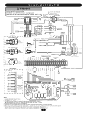
...7 LOOP 8 HARNESS 9 (10 PIN) 10 J1 1 2 3 4 5 6 7 8 9 10 11 12 13 14 15 16 J4 1 2 J2 - Secondary 24v/60va. (GL CONTROL BOARD) For reference primary wire colors: 120v black, 208v red, 230v orange, 460v purple, 575v grey 4. THREE PHASE SCHEMATIC YELLOW W A R N I N G To protect against fire and... RELAY • Replace ONLY with an internal pilot duty thermal overload device or an external line monitoring system. 6. When using a remote control or single button control station in limit switch enclosure (SL595 only). 5. Voltage: 208/230/460/575 volt 3 phase. 2. R2 BK + RD (...
...7 LOOP 8 HARNESS 9 (10 PIN) 10 J1 1 2 3 4 5 6 7 8 9 10 11 12 13 14 15 16 J4 1 2 J2 - Secondary 24v/60va. (GL CONTROL BOARD) For reference primary wire colors: 120v black, 208v red, 230v orange, 460v purple, 575v grey 4. THREE PHASE SCHEMATIC YELLOW W A R N I N G To protect against fire and... RELAY • Replace ONLY with an internal pilot duty thermal overload device or an external line monitoring system. 6. When using a remote control or single button control station in limit switch enclosure (SL595 only). 5. Voltage: 208/230/460/575 volt 3 phase. 2. R2 BK + RD (...


