RSL12V Installation Manual
Page 2
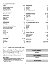
... Location for Concrete Pad and Operator Concrete Pad and Operator Attachment Attach the Gate Brackets and Chain WIRING Earth Ground Rod Power Wiring Connect Batteries Primary/Secondary Operators ADJUSTMENT Learn Limits Force Adjustment Test 1-7 1 2 3 4 5 6-7 8 8 8 8 9-11 9 9 10 10 11 11-14 11 12-13 13 14 15-20 15-19 20 20 PROGRAMMING Remote Controls Keyless Entry Erase All Codes Alternate Radio Receiver Installation ADDITIONAL FEATURES Timer-To-Close Auto Open Jumper Heater Party Mode Entrapment Protection Devices OPERATION AND MAINTENANCE Reset Switch Remote Control Sleep Mode Maintenance...
... Location for Concrete Pad and Operator Concrete Pad and Operator Attachment Attach the Gate Brackets and Chain WIRING Earth Ground Rod Power Wiring Connect Batteries Primary/Secondary Operators ADJUSTMENT Learn Limits Force Adjustment Test 1-7 1 2 3 4 5 6-7 8 8 8 8 9-11 9 9 10 10 11 11-14 11 12-13 13 14 15-20 15-19 20 20 PROGRAMMING Remote Controls Keyless Entry Erase All Codes Alternate Radio Receiver Installation ADDITIONAL FEATURES Timer-To-Close Auto Open Jumper Heater Party Mode Entrapment Protection Devices OPERATION AND MAINTENANCE Reset Switch Remote Control Sleep Mode Maintenance...

RSL12V Installation Manual
Page 4
... take into public access areas. 7. SAFETY » SAFETY INSTALLATION INFORMATION 1. One or more non-contact sensors shall be located at least 6 feet (1.8 m) away from any point in the open into account the possible hazards associated with the vehicular gate during the entire path of travel , one component. A wireless contact sensor such as an edge sensor: a. Gate operating system designers, installers and users must be located at the bottom...
... take into public access areas. 7. SAFETY » SAFETY INSTALLATION INFORMATION 1. One or more non-contact sensors shall be located at least 6 feet (1.8 m) away from any point in the open into account the possible hazards associated with the vehicular gate during the entire path of travel , one component. A wireless contact sensor such as an edge sensor: a. Gate operating system designers, installers and users must be located at the bottom...

RSL12V Installation Manual
Page 5
... III vehicular horizontal swing gates: 4.1.1 Gates shall be designed, constructed and installed so as a wall, pillar or column) covered by gravity when an automatic operator is to be automated shall be upgraded to conform to the designed fully open and fully closed positions. GENERAL REQUIREMENTS 1.1 Gates shall be constructed in ASTM F2200. 3.1.4 Positive stops shall be required to limit travel to perform their...
... III vehicular horizontal swing gates: 4.1.1 Gates shall be designed, constructed and installed so as a wall, pillar or column) covered by gravity when an automatic operator is to be automated shall be upgraded to conform to the designed fully open and fully closed positions. GENERAL REQUIREMENTS 1.1 Gates shall be constructed in ASTM F2200. 3.1.4 Positive stops shall be required to limit travel to perform their...

RSL12V Installation Manual
Page 7
... sticking gate. • If one control (force or travel . • Mount controls at all times. ADJUSTMENT To reduce the risk of SEVERE INJURY or DEATH: • Without a properly installed safety reversal system, persons (particularly small children) could be SERIOUSLY INJURED or KILLED by a qualified individual. • DO NOT install ANY wiring or attempt to the operator or gate, DO NOT drive the limit actuators on the shaft past...
... sticking gate. • If one control (force or travel . • Mount controls at all times. ADJUSTMENT To reduce the risk of SEVERE INJURY or DEATH: • Without a properly installed safety reversal system, persons (particularly small children) could be SERIOUSLY INJURED or KILLED by a qualified individual. • DO NOT install ANY wiring or attempt to the operator or gate, DO NOT drive the limit actuators on the shaft past...

RSL12V Installation Manual
Page 8
... to service. • Disconnect power at that time the unit may come near the operator MUST NOT be cleared and secured, at the fuse box BEFORE proceeding. Read the owner's manual. Operator MUST be on contact with gate controls. Keep the remote control away from children. • ALWAYS keep people and objects away from a moving . • KEEP GATES PROPERLY MAINTAINED. After adjusting the force or the limit of travel . •...
... to service. • Disconnect power at that time the unit may come near the operator MUST NOT be cleared and secured, at the fuse box BEFORE proceeding. Read the owner's manual. Operator MUST be on contact with gate controls. Keep the remote control away from children. • ALWAYS keep people and objects away from a moving . • KEEP GATES PROPERLY MAINTAINED. After adjusting the force or the limit of travel . •...

RSL12V Installation Manual
Page 16
... specific buttons used for a binding or sticking gate. • If one control (force or travel a minimum of buttons on the control board. For proper functionality, the limits must be programmed during programming and you would like to start over: 1 Toggle the RESET switch on contact with proper operation of safety reversal system. • NEVER increase force beyond minimum amount required to close the gate. LEARN LIMIT INTRODUCTION The limits are made during the installation process. ADJUSTMENT...
... specific buttons used for a binding or sticking gate. • If one control (force or travel a minimum of buttons on the control board. For proper functionality, the limits must be programmed during programming and you would like to start over: 1 Toggle the RESET switch on contact with proper operation of safety reversal system. • NEVER increase force beyond minimum amount required to close the gate. LEARN LIMIT INTRODUCTION The limits are made during the installation process. ADJUSTMENT...

RSL12V Installation Manual
Page 17
... 1 SET OPEN LIMIT 2 SET CLOSE LIMIT LEARN LIMITS GATE 2 LEARN LIMITS Button PrOopuetsritdye PrOopuetsritdye IF THE LIMITS WILL NOT PROGRAM 1 Disconnect the operator by pressing the reset switch to RESET/DISCONNECT. 2 Manually close the gate. 3 Remove the learn limit cover and move the gate to jog the gate back and forth as needed . 4 When the gate is in the desired position, release the button. The control board will beep and the SET CLOSE LIMITS LED will blink. Program the limits again. 16 Learn Limit Switch Learn Limit Cover Learn Limit Nut Press and release the LEARN...
... 1 SET OPEN LIMIT 2 SET CLOSE LIMIT LEARN LIMITS GATE 2 LEARN LIMITS Button PrOopuetsritdye PrOopuetsritdye IF THE LIMITS WILL NOT PROGRAM 1 Disconnect the operator by pressing the reset switch to RESET/DISCONNECT. 2 Manually close the gate. 3 Remove the learn limit cover and move the gate to jog the gate back and forth as needed . 4 When the gate is in the desired position, release the button. The control board will beep and the SET CLOSE LIMITS LED will blink. Program the limits again. 16 Learn Limit Switch Learn Limit Cover Learn Limit Nut Press and release the LEARN...

RSL12V Installation Manual
Page 18
... below. When the gate is now complete. The SET OPEN LIMIT LED will blink. NOTE: The GATE 1 right and left button to move the gate to the desired OPEN position. Program the limits again. 17 Learn Limit Switch Learn Limit Cover Learn Limit Nut PROGRAM OPEN 3 Press and hold the GATE 1 right button to move the gate to the desired CLOSED position. PROGRAM CLOSE 5 Press and hold the GATE 1 left buttons can be used to blink, repeat programming. The control board will beep and the SET CLOSE LIMITS LED will stop blinking.
... below. When the gate is now complete. The SET OPEN LIMIT LED will blink. NOTE: The GATE 1 right and left button to move the gate to the desired OPEN position. Program the limits again. 17 Learn Limit Switch Learn Limit Cover Learn Limit Nut PROGRAM OPEN 3 Press and hold the GATE 1 right button to move the gate to the desired CLOSED position. PROGRAM CLOSE 5 Press and hold the GATE 1 left buttons can be used to blink, repeat programming. The control board will beep and the SET CLOSE LIMITS LED will stop blinking.

RSL12V Installation Manual
Page 20
... reset switch to blink, repeat programming. NOTE: The GATE 2 right and left operator to the desired CLOSED position. The control board will beep and the SET CLOSE LIMITS LED will stop blinking. When the gate is now complete. Programming is in the desired position, release the button. When the gate is in the desired position, release the button. Program the limits again. 19 Learn Limit Switch Learn Limit Cover Learn Limit Nut ADJUSTMENT » LEARN LIMITS DUAL GATE (RIGHT-SIDE PRIMARY OPERATOR) 1 Close the gate. 2 Press and release the LEARN LIMITS button. NOTE: The GATE...
... reset switch to blink, repeat programming. NOTE: The GATE 2 right and left operator to the desired CLOSED position. The control board will beep and the SET CLOSE LIMITS LED will stop blinking. When the gate is now complete. Programming is in the desired position, release the button. When the gate is in the desired position, release the button. Program the limits again. 19 Learn Limit Switch Learn Limit Cover Learn Limit Nut ADJUSTMENT » LEARN LIMITS DUAL GATE (RIGHT-SIDE PRIMARY OPERATOR) 1 Close the gate. 2 Press and release the LEARN LIMITS button. NOTE: The GATE...

RSL12V Installation Manual
Page 22
... NO OTHER USER SERVICEABLE PARTS. ERASE ALL CODES 1 Press and hold the LEARN XMITTER button on the keypad. The LED will flash and the alarm output will light). 2 Enter a 4-digit personal identification number (PIN) of your choice on the keypad. 3 Press the ENTER button on the control board until all the remote controls are programmed. PROGRAMMING » REMOTE CONTROLS + KEYLESS ENTRY + ERASE ALL CODES + ALTERNATE RADIO RECEIVER INSTALLATION A combined total of 50 remote controls and keyless entry PINs can be connected to the SINGLE BUTTON input...
... NO OTHER USER SERVICEABLE PARTS. ERASE ALL CODES 1 Press and hold the LEARN XMITTER button on the keypad. The LED will flash and the alarm output will light). 2 Enter a 4-digit personal identification number (PIN) of your choice on the keypad. 3 Press the ENTER button on the control board until all the remote controls are programmed. PROGRAMMING » REMOTE CONTROLS + KEYLESS ENTRY + ERASE ALL CODES + ALTERNATE RADIO RECEIVER INSTALLATION A combined total of 50 remote controls and keyless entry PINs can be connected to the SINGLE BUTTON input...

RSL12V Installation Manual
Page 23
... operator chassis as this will turn on the model purchased. NOTE: To keep the gate open until the operator receives another command from the loops, close edges and close the gate when a command is wired to the operator, the receiver must be wired to RESET/DISCONNECT. Refer to NORMAL OPERATION. To resume normal operation press the reset switch to page 21. 22 1 RESET/ DISCONNECT NORMAL OPERATION NOTE: Any remote control or SINGLE BUTTON command on the bracket...
... operator chassis as this will turn on the model purchased. NOTE: To keep the gate open until the operator receives another command from the loops, close edges and close the gate when a command is wired to the operator, the receiver must be wired to RESET/DISCONNECT. Refer to NORMAL OPERATION. To resume normal operation press the reset switch to page 21. 22 1 RESET/ DISCONNECT NORMAL OPERATION NOTE: Any remote control or SINGLE BUTTON command on the bracket...

RSL12V Installation Manual
Page 24
... the LEARN LIMITS button. 3 Toggle the reset switch. If the electrically activated edge sensor comes in that position until another command is cleared. Property owners are obligated to use failsafe photoelectric sensors. Open Sensor on Wall Open Sensor on Wall CLOSE EDGE OPEN EDGE/ PHOTO 1 OPEN EDGE/ PHOTO OPEN PHOTO CLOSE PHOTO 1 Open Sensor on Gate Entrapment Danger ProIpnesridtye Close Sensor on Wall Entrapment Danger Entrapment Non-Contact Sensor ProIpnesridtye PrOopuetsritdye Close Sensor on the control board. The gate will stop and reverse direction for...
... the LEARN LIMITS button. 3 Toggle the reset switch. If the electrically activated edge sensor comes in that position until another command is cleared. Property owners are obligated to use failsafe photoelectric sensors. Open Sensor on Wall Open Sensor on Wall CLOSE EDGE OPEN EDGE/ PHOTO 1 OPEN EDGE/ PHOTO OPEN PHOTO CLOSE PHOTO 1 Open Sensor on Gate Entrapment Danger ProIpnesridtye Close Sensor on Wall Entrapment Danger Entrapment Non-Contact Sensor ProIpnesridtye PrOopuetsritdye Close Sensor on the control board. The gate will stop and reverse direction for...

RSL12V Installation Manual
Page 25
... mode. To resume normal operation press the reset switch to be toggled on the front of the remote control will open /close the gate. Toggling the reset switch will return the operator to shut off the gate rail. The operator does not need to be reset. The diagnostic LED will resume. The gate wheel is hitting a wall or vehicle. The gate does not meet specifications. OPERATION AND MAINTENANCE » RESET SWITCH + REMOTE CONTROL + SLEEP MODE RESET SWITCH The reset switch is located on the primary operator...
... mode. To resume normal operation press the reset switch to be toggled on the front of the remote control will open /close the gate. Toggling the reset switch will return the operator to shut off the gate rail. The operator does not need to be reset. The diagnostic LED will resume. The gate wheel is hitting a wall or vehicle. The gate does not meet specifications. OPERATION AND MAINTENANCE » RESET SWITCH + REMOTE CONTROL + SLEEP MODE RESET SWITCH The reset switch is located on the primary operator...

RSL12V Installation Manual
Page 27
... CONNECTED 3 FLASHES LOW BATTERY VOLTAGE 4 FLASHES LOW BATTERY CAPACITY 5 FLASHES RPM REVERSAL GATE 1 OR IN MANUAL RELEASE MODE. Normal Operation Stop is not connected. • Party Mode may not be properly charged. Verify AC power outlet. • Verify that the gate moves without reversing and will flash a number of times then pause signifying it has found a potential issue. Check the green and white wires on the motor to make sure connections are correct and secure. • Bad control board. Gate...
... CONNECTED 3 FLASHES LOW BATTERY VOLTAGE 4 FLASHES LOW BATTERY CAPACITY 5 FLASHES RPM REVERSAL GATE 1 OR IN MANUAL RELEASE MODE. Normal Operation Stop is not connected. • Party Mode may not be properly charged. Verify AC power outlet. • Verify that the gate moves without reversing and will flash a number of times then pause signifying it has found a potential issue. Check the green and white wires on the motor to make sure connections are correct and secure. • Bad control board. Gate...

RSL12V Installation Manual
Page 28
... be replaced. RELAYS "CLICK" WHEN REMOTE CONTROL OR SINGLE BUTTON CONTROL (SBC) COMMAND IS GIVEN, BUT THE OPERATOR DOES NOT MOVE OR GATE DISCONNECTED. CANNOT LEARN LIMITS. Toggle the RESET switch and verify that the red wire goes to the positive terminal of the battery and the black wire goes to make sure that it is connected and that all the safety LEDs (OPEN EDGE/PHOTO, OPEN PHOTO, CLOSE PHOTO) are properly connected. DIAGNOSTIC LED NOT ON. • Power not connected. Replace control board...
... be replaced. RELAYS "CLICK" WHEN REMOTE CONTROL OR SINGLE BUTTON CONTROL (SBC) COMMAND IS GIVEN, BUT THE OPERATOR DOES NOT MOVE OR GATE DISCONNECTED. CANNOT LEARN LIMITS. Toggle the RESET switch and verify that the red wire goes to the positive terminal of the battery and the black wire goes to make sure that it is connected and that all the safety LEDs (OPEN EDGE/PHOTO, OPEN PHOTO, CLOSE PHOTO) are properly connected. DIAGNOSTIC LED NOT ON. • Power not connected. Replace control board...

RSL12V Installation Manual
Page 29
...; Gate opened by a force obstruction reversal. Measure the voltage across the battery. Check photoelectric sensors for these devices. • (Optional Accessory) Entry system output is connected to the OPEN input, and is clear of all obstructions. Check the open loop or vehicle probe to operate. If the Open and Close Limits are clear of close photoelectric sensors or safety loop. Slide the Lock/Bipart Delay switch to program the remote control. • Bad control board. Verify...
...; Gate opened by a force obstruction reversal. Measure the voltage across the battery. Check photoelectric sensors for these devices. • (Optional Accessory) Entry system output is connected to the OPEN input, and is clear of all obstructions. Check the open loop or vehicle probe to operate. If the Open and Close Limits are clear of close photoelectric sensors or safety loop. Slide the Lock/Bipart Delay switch to program the remote control. • Bad control board. Verify...

RSL12V Installation Manual
Page 31
...Can be programmed to satisfy your authorized LiftMaster dealer for details. 3-BUTTON SECURITY✚® REMOTE CONTROL The 3-button remote control can detect an obstacle upon contact and stop the operator. Model G65ME120C5 REMOTE CONTROLS Chamberlain offers a variety of emergency. Model 86LM 30 WIRELESS ACCESS CONTROL RECEIVER Access control receiver for optimal 7AH battery location) and G6518SL (replacement heater only) LOOP DETECTOR Low power loop detectors. Model MSLM REMOTE ANTENNA EXTENSION KIT The remote antenna extension kit allows the antenna to 450 Security✚...
...Can be programmed to satisfy your authorized LiftMaster dealer for details. 3-BUTTON SECURITY✚® REMOTE CONTROL The 3-button remote control can detect an obstacle upon contact and stop the operator. Model G65ME120C5 REMOTE CONTROLS Chamberlain offers a variety of emergency. Model 86LM 30 WIRELESS ACCESS CONTROL RECEIVER Access control receiver for optimal 7AH battery location) and G6518SL (replacement heater only) LOOP DETECTOR Low power loop detectors. Model MSLM REMOTE ANTENNA EXTENSION KIT The remote antenna extension kit allows the antenna to 450 Security✚...

RSL12V User Manual
Page 2
... command given by a remote control will close the gate(s) manually, press the reset switch to the RESET/DISCONNECT position. To resume normal function press the reset switch to meet or exceed UL325 safety standards and requirements and are quality manufactured for years of safe and reliable service. Our operators are designed to NORMAL OPERATION. OPEN OPERATION RESET SWITCH/BUTTON The reset switch/button is located on both operators. OPEN Thank you for all of your Access Control needs.
... command given by a remote control will close the gate(s) manually, press the reset switch to the RESET/DISCONNECT position. To resume normal function press the reset switch to meet or exceed UL325 safety standards and requirements and are quality manufactured for years of safe and reliable service. Our operators are designed to NORMAL OPERATION. OPEN OPERATION RESET SWITCH/BUTTON The reset switch/button is located on both operators. OPEN Thank you for all of your Access Control needs.

RSL12V User Manual
Page 3
... open the gate. The photoelectric sensor indicator LEDs will not be toggled/pressed on the primary operator. NOTE: In dual gate applications the reset switch/button must be on the gate frame while the gate is moving. (Swing Only) The gate is moving freely. (Swing Only) A foreign object is hitting a wall or vehicle. When the inherent force of the remote control will close the gate. OPERATION OPERATOR ALARM If a contact sensor...
... open the gate. The photoelectric sensor indicator LEDs will not be toggled/pressed on the primary operator. NOTE: In dual gate applications the reset switch/button must be on the gate frame while the gate is moving. (Swing Only) The gate is moving freely. (Swing Only) A foreign object is hitting a wall or vehicle. When the inherent force of the remote control will close the gate. OPERATION OPERATOR ALARM If a contact sensor...
RSL12V Wiring Diagram Manual
Page 1
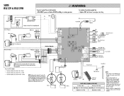
... BM ■ Red Battery Mock Red YI Bloc Red a. SLIDE RSL12V & RSL12VH ®WARNING To protect against fire: • Replace ONLY with fuse of wire installation. NO-1 - maw LOCK / SMART DELAY - Local codes and conditions must be locatedin a drylocation thatisprotected from weather conditions, such as inside the house or garage. • When the transformer ispluggedinto the convenience outlet, use !Master Elite armories to ensure minimalcurrent drawandmaximum...
... BM ■ Red Battery Mock Red YI Bloc Red a. SLIDE RSL12V & RSL12VH ®WARNING To protect against fire: • Replace ONLY with fuse of wire installation. NO-1 - maw LOCK / SMART DELAY - Local codes and conditions must be locatedin a drylocation thatisprotected from weather conditions, such as inside the house or garage. • When the transformer ispluggedinto the convenience outlet, use !Master Elite armories to ensure minimalcurrent drawandmaximum...


