MGJ User's Guide Manual
Page 2
...® is shipped from the factory in standard C2 wiring type (factory default). Some wiring types will blink once when in C2 and twice when in radio receiver that can be enabled when LiftMaster Commercial Protector operating up to reset wiring type. ** Restricted close mode requires a constant pressure... of feature that is compatible with our WARNING BASIC PROGRAMMING DETERMINE THE WIRING TYPE The functionality of the door. • Or ANY other control (automatic or manual) is based on purchasing a quality, LiftMaster Medium Duty existing 315 MHz product line as well as a Timer ...
...® is shipped from the factory in standard C2 wiring type (factory default). Some wiring types will blink once when in C2 and twice when in radio receiver that can be enabled when LiftMaster Commercial Protector operating up to reset wiring type. ** Restricted close mode requires a constant pressure... of feature that is compatible with our WARNING BASIC PROGRAMMING DETERMINE THE WIRING TYPE The functionality of the door. • Or ANY other control (automatic or manual) is based on purchasing a quality, LiftMaster Medium Duty existing 315 MHz product line as well as a Timer ...
MGJ User's Guide Manual
Page 3
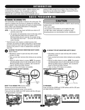
...6 7 K2 LT C29 R24 P1 D9 LMEP1 LMEP2 COM INTRLK STOP CLOSE OPEN LEARN STOP CLOSE OPEN LEDD14 1 2 3 4 5 6 7 Photo Eye 3 D B2 WIRING TYPE WITH MONITORED SAFETY DEVICE • Momentary contact to open , close and stop . • Open override that reverses when closing by any opening device. •...SAFETY DEVICE Sensing Edge TO PROGRAM Start with operator in factory default C2 mode. NOTE: The operator will automatically convert to B2 wiring (option D) when Monitored Safety Device is installed. (See accessories page for Monitored Safety Devices) • Timer to Close (TTC)...
...6 7 K2 LT C29 R24 P1 D9 LMEP1 LMEP2 COM INTRLK STOP CLOSE OPEN LEARN STOP CLOSE OPEN LEDD14 1 2 3 4 5 6 7 Photo Eye 3 D B2 WIRING TYPE WITH MONITORED SAFETY DEVICE • Momentary contact to open , close and stop . • Open override that reverses when closing by any opening device. •...SAFETY DEVICE Sensing Edge TO PROGRAM Start with operator in factory default C2 mode. NOTE: The operator will automatically convert to B2 wiring (option D) when Monitored Safety Device is installed. (See accessories page for Monitored Safety Devices) • Timer to Close (TTC)...
MGJ User's Guide Manual
Page 7
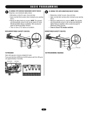
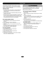
... the door from obstruction, check safety devices. The door should close if photo eyes are installed. TEST REMOTE CONTROL * Requires B2 wiring type and compatible LiftMaster remote control. Door should not close . Press CLOSE button. (The door should stop .) 3. Press STOP button. (The door ...should move in B2 mode.) 5. Press the CLOSE button. Press CLOSE button. In C2 wiring the remote control will flash 7 times on unless ...
... the door from obstruction, check safety devices. The door should close if photo eyes are installed. TEST REMOTE CONTROL * Requires B2 wiring type and compatible LiftMaster remote control. Door should not close . Press CLOSE button. (The door should stop .) 3. Press STOP button. (The door ...should move in B2 mode.) 5. Press the CLOSE button. Press CLOSE button. In C2 wiring the remote control will flash 7 times on unless ...
MGJ User's Guide Manual
Page 12
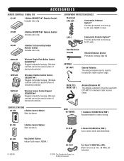
... controls.) Wireless Access Control Keypad SECURITY✚®: Rugged composite housing. (Wireless controls can be used with EXT-ANT for control wiring. 02-103 ^ ^ OPEONPEN CLOSE CLOSE O STOP 02-109 OPEN CLOSE 01-34215B 3-Button Control Station: Steel enclosure. 21-...white andOPwEN hite/black. NEMA-O4PEN rated. CONTROL STATIONS 02-102 2-Button Control Station: Steel enclosure. OPEN CLOSE WIRE 65-7WIREL 7 Conductor 20 AWG Wire (500'): Recommended for maximum radio receiver range. OPEN OPEN ACCESSORIES REMOTE CONTROLS 315MHz 371LM OPEN 1-Button SECURITY✚&#...
... controls.) Wireless Access Control Keypad SECURITY✚®: Rugged composite housing. (Wireless controls can be used with EXT-ANT for control wiring. 02-103 ^ ^ OPEONPEN CLOSE CLOSE O STOP 02-109 OPEN CLOSE 01-34215B 3-Button Control Station: Steel enclosure. 21-...white andOPwEN hite/black. NEMA-O4PEN rated. CONTROL STATIONS 02-102 2-Button Control Station: Steel enclosure. OPEN CLOSE WIRE 65-7WIREL 7 Conductor 20 AWG Wire (500'): Recommended for maximum radio receiver range. OPEN OPEN ACCESSORIES REMOTE CONTROLS 315MHz 371LM OPEN 1-Button SECURITY✚&#...
MJ5011E QuickStart-2008 Manual
Page 1
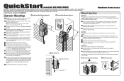
These instructions are aligned. NOTE: Intended for further information. Visit www.LiftMaster.com to locate a professional installing dealer in the electrical box enclosure. a Pull the disconnect chain (sash chain) to the operator. Connect the earth ground to ... the power wiring conduit hole in position by pulling on the wall. Make sure the operator output shaft is the responsibility of the operator. b The door may be found on the wall. Refer to Model MH instructions above or below the door shaft, and as close door properly. QuickStart model MJ/MH...
These instructions are aligned. NOTE: Intended for further information. Visit www.LiftMaster.com to locate a professional installing dealer in the electrical box enclosure. a Pull the disconnect chain (sash chain) to the operator. Connect the earth ground to ... the power wiring conduit hole in position by pulling on the wall. Make sure the operator output shaft is the responsibility of the operator. b The door may be found on the wall. Refer to Model MH instructions above or below the door shaft, and as close door properly. QuickStart model MJ/MH...
MJ5011E QuickStart-2008 Manual
Page 2
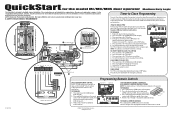
... CLOSE OPEN 1 2 3 4 5 USE COPPER WIRE ONLY 67 CONTROL WIRING 16-22 AWG Control Wiring Knockouts 10 9 115 V PH. 1 Power Connection L1 L2 Power Wiring ONLY! Begin with door in any combination. Repeat steps 1 and 2 for the model MJ/MH/MHS door operator Medium Duty Logic This QuickStart... disabled by pressing a STOP button. The TTC will light.) 2. Press and hold the TTC button for Professional Installation Only. Visit www.LiftMaster.com to complete programming (LED will add 5 seconds to the Timer to program additional buttons. TO PROGRAM 1. Release both buttons. 3. ...
... CLOSE OPEN 1 2 3 4 5 USE COPPER WIRE ONLY 67 CONTROL WIRING 16-22 AWG Control Wiring Knockouts 10 9 115 V PH. 1 Power Connection L1 L2 Power Wiring ONLY! Begin with door in any combination. Repeat steps 1 and 2 for the model MJ/MH/MHS door operator Medium Duty Logic This QuickStart... disabled by pressing a STOP button. The TTC will light.) 2. Press and hold the TTC button for Professional Installation Only. Visit www.LiftMaster.com to complete programming (LED will add 5 seconds to the Timer to program additional buttons. TO PROGRAM 1. Release both buttons. 3. ...
MJ5011E Installation-2008 Manual
Page 3
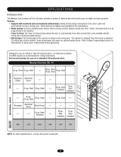
... 16 ga. Steel Insulated --- --- --- 20 ga. The operator is based on the wiring type. Refer to automatically close after a preset time (only available with B2 wiring and a monitored safety device). • Wiring Types: The functionality of reliable and safe operation. Intended for rolling sheet doors. Steel ---... or high-lift sectional doors, or rolling door products. FT) 24 ga. Steel 20 ga. Steel 22 ga. Steel --- Some wiring types will provide years of the operator is shipped from the factory in the door's path and automatically reverse a closing door. FT NOTE...
... 16 ga. Steel Insulated --- --- --- 20 ga. The operator is based on the wiring type. Refer to automatically close after a preset time (only available with B2 wiring and a monitored safety device). • Wiring Types: The functionality of reliable and safe operation. Intended for rolling sheet doors. Steel ---... or high-lift sectional doors, or rolling door products. FT) 24 ga. Steel 20 ga. Steel 22 ga. Steel --- Some wiring types will provide years of the operator is shipped from the factory in the door's path and automatically reverse a closing door. FT NOTE...
MJ5011E Installation-2008 Manual
Page 4
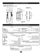
...(16.1 cm) (16.1 cm) 6.133"" (15.57 cm) 3.63" (39..6232"cm) 22..9911""(7.39 cm) MOUNTING DIMENSIONS A - OUTPUT RPM: MJ 80 RPM MH 80 RPM MHS 38.6 RPM LIMIT ADJUST Fully adjustable up to + 50˚C) 4 ENTRAPMENT PROTECTION: . . . . . MHS Both disconnects described...CONTROL WIRING 16-22 AWG MECHANICAL DOOR SPEED Approximately 9" (23 cm) / second depending on door setup OUTPUT FORCE 125 ft. MJ Floor level disconnect for emergency manual chain hoist operation. lbs/ sec. Wall Mounting B - Supports both monitored and non-monitored safety devices including LiftMaster ...
...(16.1 cm) (16.1 cm) 6.133"" (15.57 cm) 3.63" (39..6232"cm) 22..9911""(7.39 cm) MOUNTING DIMENSIONS A - OUTPUT RPM: MJ 80 RPM MH 80 RPM MHS 38.6 RPM LIMIT ADJUST Fully adjustable up to + 50˚C) 4 ENTRAPMENT PROTECTION: . . . . . MHS Both disconnects described...CONTROL WIRING 16-22 AWG MECHANICAL DOOR SPEED Approximately 9" (23 cm) / second depending on door setup OUTPUT FORCE 125 ft. MJ Floor level disconnect for emergency manual chain hoist operation. lbs/ sec. Wall Mounting B - Supports both monitored and non-monitored safety devices including LiftMaster ...
MJ5011E Installation-2008 Manual
Page 10
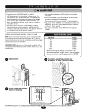
... or in the area near the operator MUST NOT be connected to the operator's terminal is required, the wire must be properly grounded. Use conduit knockouts for wiring as DISTANCE 50' indicated on the electrical box labels. 100' 200' GAUGE 14 AWG 12 AWG 8 ...AWG. Operator MUST be properly grounded and connected in accordance with local electrical codes. EMENPTOWER AND GROUND WIRING CONNECTIAONVS ERTISSEMENTPOWER WIRING CHART ON AVERTISSEMENT NOTE: Power and control wiring must be gauged down to service. • Disconnect power at that can be performed until you ...
... or in the area near the operator MUST NOT be connected to the operator's terminal is required, the wire must be properly grounded. Use conduit knockouts for wiring as DISTANCE 50' indicated on the electrical box labels. 100' 200' GAUGE 14 AWG 12 AWG 8 ...AWG. Operator MUST be properly grounded and connected in accordance with local electrical codes. EMENPTOWER AND GROUND WIRING CONNECTIAONVS ERTISSEMENTPOWER WIRING CHART ON AVERTISSEMENT NOTE: Power and control wiring must be gauged down to service. • Disconnect power at that can be performed until you ...
MJ5011E Installation-2008 Manual
Page 11
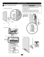
AVERTISSEMENOTperator Conduit ATTENTION ^OPEN CLOSE O STOP ^ ^ ^ Wire 3-button control station Power AUX AANUT X ANT AUX ANT ^^^^ TTC LEARN STOP CLOSE OPEN LEDD14 1 2 3 4 5 6 7 LMEP1 LMEP2 COM INTRLK STOP CLOSE OPEN ^OPEN CLOSE O STOP ... ANY other control (automatic or manual) is used . INSTALLATION WARNING 12 INSTALL 3-BUTTON CONTROL STATION Select location for ALL installations. Select appropriate knockout and run wire according to local electrical code from operator to wall PRECAUCIÓN 11
AVERTISSEMENOTperator Conduit ATTENTION ^OPEN CLOSE O STOP ^ ^ ^ Wire 3-button control station Power AUX AANUT X ANT AUX ANT ^^^^ TTC LEARN STOP CLOSE OPEN LEDD14 1 2 3 4 5 6 7 LMEP1 LMEP2 COM INTRLK STOP CLOSE OPEN ^OPEN CLOSE O STOP ... ANY other control (automatic or manual) is used . INSTALLATION WARNING 12 INSTALL 3-BUTTON CONTROL STATION Select location for ALL installations. Select appropriate knockout and run wire according to local electrical code from operator to wall PRECAUCIÓN 11
MJ5011E Installation-2008 Manual
Page 12
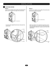
... Press the plastic standoff into the hole in the side of the electrical box. Antenna Wire Ties Standoff Cut these Wire Ties Attach the antenna to the edge of the electrical box. Bend antenna across the front of the electrical box, ensuring that the antenna is... 4" away from the front of the electrical box. Wire Ties Antenna Cut Wire Tie Antenna Cut Wire Ties 12 INSTALLATION 13 SETUP RADIO ANTENNA Option A Locate the wire antenna on the outside of the electrical box. Option B Locate the wire antenna on the outside of the electrical box. Cut the...
... Press the plastic standoff into the hole in the side of the electrical box. Antenna Wire Ties Standoff Cut these Wire Ties Attach the antenna to the edge of the electrical box. Bend antenna across the front of the electrical box, ensuring that the antenna is... 4" away from the front of the electrical box. Wire Ties Antenna Cut Wire Tie Antenna Cut Wire Ties 12 INSTALLATION 13 SETUP RADIO ANTENNA Option A Locate the wire antenna on the outside of the electrical box. Option B Locate the wire antenna on the outside of the electrical box. Cut the...
MJ5011E Installation-2008 Manual
Page 14
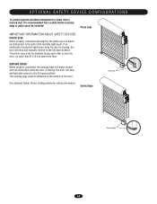
... or photo eyes) be installed facing each other across the door, no more than 6" (15 cm) above the floor. See Optional Safety Device Configurations for wiring information. Photo Eyes IMPORTANT INFORMATION ABOUT SAFETY DEVICES PHOTO EYES When properly connected and aligned, the photo eye will detect an obstruction in the path...
... or photo eyes) be installed facing each other across the door, no more than 6" (15 cm) above the floor. See Optional Safety Device Configurations for wiring information. Photo Eyes IMPORTANT INFORMATION ABOUT SAFETY DEVICES PHOTO EYES When properly connected and aligned, the photo eye will detect an obstruction in the path...
MJ5011E Installation-2008 Manual
Page 15
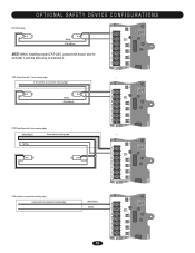
...LEARN STOP CLOSE OPEN LEDD14 2 3 4 LMEP1 LMEP2 COM INTRLK STOP CLOSE OPEN 5 6 7 AUX ANT AUX ANT CPS Photo-Eyes with 4-wire sensing edge (White/Black) 4-wire electric sensing edge (White) TTC ^^^^ 1 LEARN STOP CLOSE OPEN LEDD14 2 3 4 LMEP1 LMEP2 COM INTRLK STOP CLOSE OPEN 5 6 7 ...AUX ANT AUX ANT TTC ^^^^ 1 LEARN STOP CLOSE OPEN LEDD14 2 3 4 LMEP1 LMEP2 COM INTRLK STOP CLOSE OPEN 2-Wire electric or pneumatic sensing edge 2-wire electric or pneumatic sensing edge (White/Black) (White) 15 5 6 7 ANT X ANT TTC ^^^^ 1 LEARN STOP CLOSE OPEN LEDD14 ...
...LEARN STOP CLOSE OPEN LEDD14 2 3 4 LMEP1 LMEP2 COM INTRLK STOP CLOSE OPEN 5 6 7 AUX ANT AUX ANT CPS Photo-Eyes with 4-wire sensing edge (White/Black) 4-wire electric sensing edge (White) TTC ^^^^ 1 LEARN STOP CLOSE OPEN LEDD14 2 3 4 LMEP1 LMEP2 COM INTRLK STOP CLOSE OPEN 5 6 7 ...AUX ANT AUX ANT TTC ^^^^ 1 LEARN STOP CLOSE OPEN LEDD14 2 3 4 LMEP1 LMEP2 COM INTRLK STOP CLOSE OPEN 2-Wire electric or pneumatic sensing edge 2-wire electric or pneumatic sensing edge (White/Black) (White) 15 5 6 7 ANT X ANT TTC ^^^^ 1 LEARN STOP CLOSE OPEN LEDD14 ...

MJ5011E Installation-2008 Manual
Page 16
Not Provided Used during programming and diagnosing error codes Field wiring connections Factory wiring harness connection 16 LOGIC BOARD LAYOUT 432 1 5 6 AUX AANUT X ANT ^^^^ 7 TTC LEARN STOP CLOSE OPEN LEDD14 1 2 3 4 5 6 7 LMEP1 LMEP2 COM INTRLK STOP CLOSE ...5 6 7 8 9 10 DESCRIPTION Open Button Close Button Stop Button Learn Button Timer to Close Button Purple Wire Antenna Auxiliary Antenna Connection LED Field Wiring Terminal Factory Wiring Connector FUNCTION Open Door Close Door Stop Door Programs the remote controls and performs additional programming Programs the Timer to...
Not Provided Used during programming and diagnosing error codes Field wiring connections Factory wiring harness connection 16 LOGIC BOARD LAYOUT 432 1 5 6 AUX AANUT X ANT ^^^^ 7 TTC LEARN STOP CLOSE OPEN LEDD14 1 2 3 4 5 6 7 LMEP1 LMEP2 COM INTRLK STOP CLOSE ...5 6 7 8 9 10 DESCRIPTION Open Button Close Button Stop Button Learn Button Timer to Close Button Purple Wire Antenna Auxiliary Antenna Connection LED Field Wiring Terminal Factory Wiring Connector FUNCTION Open Door Close Door Stop Door Programs the remote controls and performs additional programming Programs the Timer to...
MJ5011E Installation-2008 Manual
Page 17
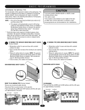
...will automatically convert to the close . • Open override that reverses when closing by any monitored safety devices. AVERTISSEMENT ATTENTION C2 WIRING TYPE WITHOUT MONITORED SAFETY DEVICE A (Factory Default) • Momentary contact to open and stop with constant pressure to close limit ... will go into a Restricted Close mode**. The operator is installed. (See accessories page for ALL installations. Some wiring types will automatically convert to B2 wiring (option D) when Monitored Safety Device is shipped from the factory in B2. 2. Refer to the operator. Reversing...
...will automatically convert to the close . • Open override that reverses when closing by any monitored safety devices. AVERTISSEMENT ATTENTION C2 WIRING TYPE WITHOUT MONITORED SAFETY DEVICE A (Factory Default) • Momentary contact to open and stop with constant pressure to close limit ... will go into a Restricted Close mode**. The operator is installed. (See accessories page for ALL installations. Some wiring types will automatically convert to B2 wiring (option D) when Monitored Safety Device is shipped from the factory in B2. 2. Refer to the operator. Reversing...
MJ5011E Installation-2008 Manual
Page 18
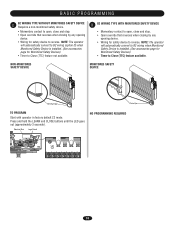
...LMEP2 COM INTRLK STOP CLOSE OPEN LEARN STOP CLOSE OPEN LEDD14 1 2 3 45 67 18 NOTE: The operator will automatically convert to B2 wiring (option D) when Monitored Safety Device is installed. (See accessories page for Monitored Safety Devices) • Timer to Close (TTC) feature ...available. NOTE: The operator will automatically convert to B2 wiring when Monitored Safety Device is installed. (See accessories page for Monitored Safety Devices) • Timer to Close (TTC) feature not available....
...LMEP2 COM INTRLK STOP CLOSE OPEN LEARN STOP CLOSE OPEN LEDD14 1 2 3 45 67 18 NOTE: The operator will automatically convert to B2 wiring (option D) when Monitored Safety Device is installed. (See accessories page for Monitored Safety Devices) • Timer to Close (TTC) feature ...available. NOTE: The operator will automatically convert to B2 wiring when Monitored Safety Device is installed. (See accessories page for Monitored Safety Devices) • Timer to Close (TTC) feature not available....
MJ5011E Installation-2008 Manual
Page 20
...C2 mode. (The door should open.) 2. The door AVERTISSEMENT should open direction.) 2. Remove the obstruction. 5. In C2 wiring the remote control will flash 7 times on unless all safety and entrapment protection devices have read and understand all controls and ... CONTROL STATION ATTENTION 1. Release CLOSE button. TEST THE SAFETY DEVICES (IF INSTALLED) 1. TEST REMOTE CONTROL * Requires B2 wiring type and compatible LiftMaster remote control. ADVERTENCIA PRECAUCIÓN ADVERTENCIA ADVERTENCIA 20 Press OPEN button. (The door should close . Press CLOSE button. ...
...C2 mode. (The door should open.) 2. The door AVERTISSEMENT should open direction.) 2. Remove the obstruction. 5. In C2 wiring the remote control will flash 7 times on unless all safety and entrapment protection devices have read and understand all controls and ... CONTROL STATION ATTENTION 1. Release CLOSE button. TEST THE SAFETY DEVICES (IF INSTALLED) 1. TEST REMOTE CONTROL * Requires B2 wiring type and compatible LiftMaster remote control. ADVERTENCIA PRECAUCIÓN ADVERTENCIA ADVERTENCIA 20 Press OPEN button. (The door should close . Press CLOSE button. ...
MJ5011E Installation-2008 Manual
Page 22
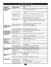
... to ensure brake lever is not activated. B) Remote control not compatible ➤ Obtain qualified LiftMaster remote control device. F) Accessory failure ➤ Attempt to cool and retry. See PROGRAMMING TTC section. E) Motor overload tripped ➤ Overload is properly wired and not activated. TROUBLESHOOTING Technical Support 1-800-528-2806 CONDITION POSSIBLE CAUSE FIX OPERATOR...
... to ensure brake lever is not activated. B) Remote control not compatible ➤ Obtain qualified LiftMaster remote control device. F) Accessory failure ➤ Attempt to cool and retry. See PROGRAMMING TTC section. E) Motor overload tripped ➤ Overload is properly wired and not activated. TROUBLESHOOTING Technical Support 1-800-528-2806 CONDITION POSSIBLE CAUSE FIX OPERATOR...
MJ5011E Installation-2008 Manual
Page 23
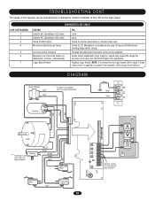
... Remove Jumper to the operator. (Not a logic board failure.) DIAGRAM Brake (Optional) Blue* Blue* * If brake is not supplied, wires are capped separately Green Black Black L2 L1 Capacitor Yellow Red Yellow Red Motor ** If interlock is applied or cycled to install external door ...interlock. Reverse the yellow and red motor wires on the logic board. # OF LED FLASHES 1 2 3 4 5 6 7 DIAGNOSTIC LED TABLE STATUS System OK. Check clutch adjustment. Operating in ...
... Remove Jumper to the operator. (Not a logic board failure.) DIAGRAM Brake (Optional) Blue* Blue* * If brake is not supplied, wires are capped separately Green Black Black L2 L1 Capacitor Yellow Red Yellow Red Motor ** If interlock is applied or cycled to install external door ...interlock. Reverse the yellow and red motor wires on the logic board. # OF LED FLASHES 1 2 3 4 5 6 7 DIAGNOSTIC LED TABLE STATUS System OK. Check clutch adjustment. Operating in ...
MJ5011E Installation-2008 Manual
Page 24
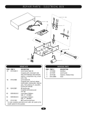
... Limit Switch Kit Complete with: Limit nut retainer, switch plates, backup plate, depress plate, limit switches (3), standoffs, screws and locknuts K3 K94-33961 Wiring Harness Complete with harness and wire ties K4 K001A6424-2 Logic Board, Medium Duty "E", 315 MHz K4 K001A6424-3 Logic Board, Medium Duty "E", 390 MHz K5 K74-31243 MOV and...
... Limit Switch Kit Complete with: Limit nut retainer, switch plates, backup plate, depress plate, limit switches (3), standoffs, screws and locknuts K3 K94-33961 Wiring Harness Complete with harness and wire ties K4 K001A6424-2 Logic Board, Medium Duty "E", 315 MHz K4 K001A6424-3 Logic Board, Medium Duty "E", 390 MHz K5 K74-31243 MOV and...

