MGJ User's Guide Manual
Page 2
... COM INTRLK STOP CLOSE OPEN LEARN STOP CLOSE OPEN LEDD14 1 2 3 4 5 6 7 ADVERTENCIA PRECAUCIÓN TO PROGRAM Photo Eye Press and hold the LEARN and STOP buttons until the LED goes out (approximately 3 seconds). The operator is installed. Refer to B2 wiring (option D) when Monitored Safety Device is released before reaching the close limit switch. The operator will automatically convert to the following descriptions of the door. • Or ANY other control (automatic or manual) is installed and aligned...
... COM INTRLK STOP CLOSE OPEN LEARN STOP CLOSE OPEN LEDD14 1 2 3 4 5 6 7 ADVERTENCIA PRECAUCIÓN TO PROGRAM Photo Eye Press and hold the LEARN and STOP buttons until the LED goes out (approximately 3 seconds). The operator is installed. Refer to B2 wiring (option D) when Monitored Safety Device is released before reaching the close limit switch. The operator will automatically convert to the following descriptions of the door. • Or ANY other control (automatic or manual) is installed and aligned...
MGJ User's Guide Manual
Page 4
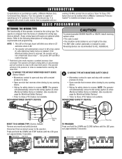
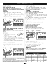
... release of timer setting. BASIC PROGRAMMING REMOTE CONTROLS SINGLE BUTTON REMOTE CONTROL Built in 315 MHz radio receiver permits as many as 20 Security✚® remote controls or dip switch remote controls in fully closed position. 2. Press and release the LEARN button (LED will become active after a preset time, adjustable from 5 to the following two conditions: (1) this device may cause undesired operation. Press and hold the LEARN button (LED will go out). Press and hold the button on the logic board (OPEN, CLOSE...
... release of timer setting. BASIC PROGRAMMING REMOTE CONTROLS SINGLE BUTTON REMOTE CONTROL Built in 315 MHz radio receiver permits as many as 20 Security✚® remote controls or dip switch remote controls in fully closed position. 2. Press and release the LEARN button (LED will become active after a preset time, adjustable from 5 to the following two conditions: (1) this device may cause undesired operation. Press and hold the LEARN button (LED will go out). Press and hold the button on the logic board (OPEN, CLOSE...
MGJ User's Guide Manual
Page 5
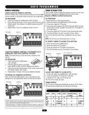
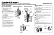
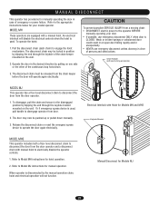
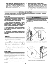
... of the continuous loop hoist chain. 3. Emergency disconnect will disable the electrical controls when the hoist is used. To operate the hoist: 1. Pull the disconnect chain (sash chain) to the appropriate instructions for your model operator. The disconnect chain must be locked in position by pulling on the wall. 2. M A N U A L D I S C O N N E C T ( M O D E L S M T / BWMATRN& INMGH ) The operators have provisions for manually operating the door in case of door arm to trolley. Chain Retaining Bracket (with pad locking provisions) ADVERTENCIA PRECAUCI...
... of the continuous loop hoist chain. 3. Emergency disconnect will disable the electrical controls when the hoist is used. To operate the hoist: 1. Pull the disconnect chain (sash chain) to the appropriate instructions for your model operator. The disconnect chain must be locked in position by pulling on the wall. 2. M A N U A L D I S C O N N E C T ( M O D E L S M T / BWMATRN& INMGH ) The operators have provisions for manually operating the door in case of door arm to trolley. Chain Retaining Bracket (with pad locking provisions) ADVERTENCIA PRECAUCI...
MGJ User's Guide Manual
Page 7
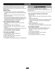
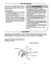
... the open the door only. 1. If the operator does not function properly, contact your installing dealer. Door should stop if in this manual. • Be sure the owner or person(s) responsible for operation of the photo eyes or sensing edge. 3. TEST THE SAFETY DEVICES (IF INSTALLED) 1. In C2 wiring the remote control will flash 7 times on unless all safety instructions included in C2 mode. (The door should stop .) TEST LIMIT ADJUSTMENT 1. Press STOP button. (The door should continue closing...
... the open the door only. 1. If the operator does not function properly, contact your installing dealer. Door should stop if in this manual. • Be sure the owner or person(s) responsible for operation of the photo eyes or sensing edge. 3. TEST THE SAFETY DEVICES (IF INSTALLED) 1. In C2 wiring the remote control will flash 7 times on unless all safety instructions included in C2 mode. (The door should stop .) TEST LIMIT ADJUSTMENT 1. Press STOP button. (The door should continue closing...
MJ5011E QuickStart-2008 Manual
Page 1
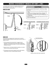
... Turn off power to the ground screw in your door. MODEL MHS This operator includes two methods of the purchaser, designer, installer and end user to door shaft and sprockets are not intended to Model MJ instructions above or below the door shaft. Please consult the manual and/or a qualified technician for push-up or pulled down operation. Do not insert the key or set screw at this time. The disconnect chain may be released...
... Turn off power to the ground screw in your door. MODEL MHS This operator includes two methods of the purchaser, designer, installer and end user to door shaft and sprockets are not intended to Model MJ instructions above or below the door shaft. Please consult the manual and/or a qualified technician for push-up or pulled down operation. Do not insert the key or set screw at this time. The disconnect chain may be released...
MJ5011E QuickStart-2008 Manual
Page 2
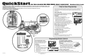
... the LEARN button (LED will add 5 seconds to the Timer to 60 seconds. Every press and release of the remote control until the LED goes out. Press and hold the button on the logic board (OPEN, CLOSE or STOP). All programmed remote controls will become enabled after the next open limit after a preset time, adjustable from 5 to Close. A SAFETY DEVICE IS HIGHLY RECOMMENDED Push Direction Limit Nut Will Move During Travel SAFETY CLOSE Limit Nuts Retaining Plate 11 Limit Switches OPEN 9 Power Wiring Knockout...
... the LEARN button (LED will add 5 seconds to the Timer to 60 seconds. Every press and release of the remote control until the LED goes out. Press and hold the button on the logic board (OPEN, CLOSE or STOP). All programmed remote controls will become enabled after the next open limit after a preset time, adjustable from 5 to Close. A SAFETY DEVICE IS HIGHLY RECOMMENDED Push Direction Limit Nut Will Move During Travel SAFETY CLOSE Limit Nuts Retaining Plate 11 Limit Switches OPEN 9 Power Wiring Knockout...
MJ5011E Installation-2008 Manual
Page 2
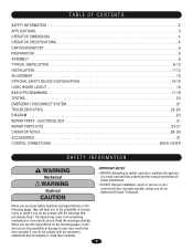
... CONTENTS SAFETY INFORMATION 2 APPLICATIONS 3 OPERATOR DIMENSIONS 4 OPERATOR SPECIFICATIONS 4 CARTON INVENTORY 5 PREPARATION 5 ASSEMBLY 6 TYPICAL INSTALLATION 6-10 INSTALLATION 11-12 ADJUSTMENT 13 OPTIONAL SAFETY DEVICE CONFIGURATION 14-15 LOGIC BOARD LAYOUT 16 BASIC PROGRAMMING 17-19 TESTING 20 EMERGENCY DISCONNECT SYSTEM 21 TROUBLESHOOTING 22-23 DIAGRAM 23 REPAIR PARTS - WARNING When you see this manual and follow all WWAARRNNININGG safety instructions. • DO NOT attempt installation, repair or service of your door and/or the AVERTISSEMENT door operator if...
... CONTENTS SAFETY INFORMATION 2 APPLICATIONS 3 OPERATOR DIMENSIONS 4 OPERATOR SPECIFICATIONS 4 CARTON INVENTORY 5 PREPARATION 5 ASSEMBLY 6 TYPICAL INSTALLATION 6-10 INSTALLATION 11-12 ADJUSTMENT 13 OPTIONAL SAFETY DEVICE CONFIGURATION 14-15 LOGIC BOARD LAYOUT 16 BASIC PROGRAMMING 17-19 TESTING 20 EMERGENCY DISCONNECT SYSTEM 21 TROUBLESHOOTING 22-23 DIAGRAM 23 REPAIR PARTS - WARNING When you see this manual and follow all WWAARRNNININGG safety instructions. • DO NOT attempt installation, repair or service of your door and/or the AVERTISSEMENT door operator if...
MJ5011E Installation-2008 Manual
Page 3
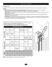
.... • Radio receiver: A factory installed radio receiver allows remote controls, keyless entries and other remote command devices to be programmed to the operator. • Timer To Close: The Timer To Close feature allows the door to Basic Programming Section for rolling sheet doors. The operator is recommended for descriptions of reliable and safe operation. Intended for use on a standard lift sectional door. APPLICATIONS INTRODUCTION This Medium Duty Commercial Door Operator includes a number of features that will require an optional safety device...
.... • Radio receiver: A factory installed radio receiver allows remote controls, keyless entries and other remote command devices to be programmed to the operator. • Timer To Close: The Timer To Close feature allows the door to Basic Programming Section for rolling sheet doors. The operator is recommended for descriptions of reliable and safe operation. Intended for use on a standard lift sectional door. APPLICATIONS INTRODUCTION This Medium Duty Commercial Door Operator includes a number of features that will require an optional safety device...
MJ5011E Installation-2008 Manual
Page 5
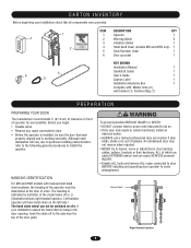
... • Disable ALL locks and remove ALL ropes connected to door BEFORE installing and operating door operator to loosen, move or adjust doors, door springs, cables, pulleys, brackets or their hardware, ALL of which are under EXTREME tension and can not be switched on the left side.) The hand chain wheel can cause SERIOUS personal INJURY. AVERTISSEMENT HAANDTINTGEIDNENTTIIFOICNATION For MH and HMS models with : Master links (2), wall bracket (1), Fastener Bag...
... • Disable ALL locks and remove ALL ropes connected to door BEFORE installing and operating door operator to loosen, move or adjust doors, door springs, cables, pulleys, brackets or their hardware, ALL of which are under EXTREME tension and can not be switched on the left side.) The hand chain wheel can cause SERIOUS personal INJURY. AVERTISSEMENT HAANDTINTGEIDNENTTIIFOICNATION For MH and HMS models with : Master links (2), wall bracket (1), Fastener Bag...
MJ5011E Installation-2008 Manual
Page 19
... the LED flashes rapidly, then release to complete programming (LED will add 5 seconds to the Timer to Comply with TTC C2 RADIO OPERATION OPEN CLOSE STOP X X X X X (3 button X remote) X X REVERSE WHILE CLOSING X TTC RESET X X WHEN OPEN X 19 TO ERASE ALL REMOTE CONTROLS Press and hold the LEARN button (over 5 seconds) until LED flashes rapidly, then release. 4. Operation is running. TO PROGRAM 1. The LED will become active after a preset time, adjustable from 5 to exit programming mode. 6. Press and hold the button on the logic board (OPEN, CLOSE or STOP...
... the LED flashes rapidly, then release to complete programming (LED will add 5 seconds to the Timer to Comply with TTC C2 RADIO OPERATION OPEN CLOSE STOP X X X X X (3 button X remote) X X REVERSE WHILE CLOSING X TTC RESET X X WHEN OPEN X 19 TO ERASE ALL REMOTE CONTROLS Press and hold the LEARN button (over 5 seconds) until LED flashes rapidly, then release. 4. Operation is running. TO PROGRAM 1. The LED will become active after a preset time, adjustable from 5 to exit programming mode. 6. Press and hold the button on the logic board (OPEN, CLOSE or STOP...
MJ5011E Installation-2008 Manual
Page 21
... loop hoist chain. 3. Or if emergency egress device is CLOSED. Electrical Interlock with pad locking provisions) ATTENTION MODEL MJ This operator has a floor level disconnect chain to disconnect the door from the door operator. 1. MODEL MHS This operator includes both a floor level disconnect chain to disconnect the door from the door operator and a disconnect chain with a manual hoist. Refer to operate the door again electrically. The door may be released from door. 2. Refer to Model MJ instructions for hoist operation. 2. MODEL MH These operators...
... loop hoist chain. 3. Or if emergency egress device is CLOSED. Electrical Interlock with pad locking provisions) ATTENTION MODEL MJ This operator has a floor level disconnect chain to disconnect the door from the door operator. 1. MODEL MHS This operator includes both a floor level disconnect chain to disconnect the door from the door operator and a disconnect chain with a manual hoist. Refer to operate the door again electrically. The door may be released from door. 2. Refer to Model MJ instructions for hoist operation. 2. MODEL MH These operators...
MJ5011E Installation-2008 Manual
Page 22
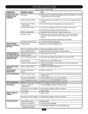
... battery in radio receiver compatible with all connections. TROUBLESHOOTING Technical Support 1-800-528-2806 CONDITION POSSIBLE CAUSE FIX OPERATOR WILL NOT RESPOND TO ANY COMMANDS A) No power ➤ Verify primary line voltage (120Vac,60Hz) is internal within motor. THE WRONG DIRECTION connection reversed DOOR DRIFTS AFTER OPERATOR STOPS A) Door not balanced properly ➤ Disconnect trolley assembly and check door for more than 5 seconds. B) Remote control not compatible ➤ Obtain qualified LiftMaster remote control device. DOOR OPENS/CLOSES Limits not adjusted...
... battery in radio receiver compatible with all connections. TROUBLESHOOTING Technical Support 1-800-528-2806 CONDITION POSSIBLE CAUSE FIX OPERATOR WILL NOT RESPOND TO ANY COMMANDS A) No power ➤ Verify primary line voltage (120Vac,60Hz) is internal within motor. THE WRONG DIRECTION connection reversed DOOR DRIFTS AFTER OPERATOR STOPS A) Door not balanced properly ➤ Disconnect trolley assembly and check door for more than 5 seconds. B) Remote control not compatible ➤ Obtain qualified LiftMaster remote control device. DOOR OPENS/CLOSES Limits not adjusted...
MJ5011E Installation-2008 Manual
Page 31
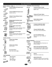
... 3-Button SECURITY✚® Remote Control: Includes visor clip. 333LM OPEN 3-Button Tri-Colored Remote Control: Includes visor clip. PRESS TO R ING CLOSE Vehicle Detection System Pneumatic Edge Kit 7 Conductor 20 AWG Wire (500'): Recommended for TO MJ, MH, and MHS.RING 10-9095 ANTENNA EXT-ANT OPEN Medium Duty Angle Mounting Bracket: CLOSE Heavy-gauge steel bracket. Key Control Station: Indoor flush mount, NEMA 1. OPEN CLOSE 31 CHAIN TENSIONERS 71-6023 Chain Tensioner: For 1" shafts 71...
... 3-Button SECURITY✚® Remote Control: Includes visor clip. 333LM OPEN 3-Button Tri-Colored Remote Control: Includes visor clip. PRESS TO R ING CLOSE Vehicle Detection System Pneumatic Edge Kit 7 Conductor 20 AWG Wire (500'): Recommended for TO MJ, MH, and MHS.RING 10-9095 ANTENNA EXT-ANT OPEN Medium Duty Angle Mounting Bracket: CLOSE Heavy-gauge steel bracket. Key Control Station: Indoor flush mount, NEMA 1. OPEN CLOSE 31 CHAIN TENSIONERS 71-6023 Chain Tensioner: For 1" shafts 71...
MJ (BLACK LINE) Manual
Page 2
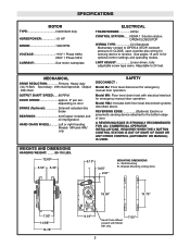
... Models MH and HMJ only. DISCONNECT : SAFETY Model MJ: Floor level disconnect for optional control settings and operating modes. MECHANICAL DRIVE REDUCTION Primary: Heavy duty (4L) V-Belt. Secondary: #48 chain/sprocket. Bracket Mounting (rolling door) A A 18.50" 14.75" A A 7.00" 10.88" 15.78" 9.19" Hand Chain Wheel present with electrical interlock for sensing device to CLOSE, open override plus wiring for emergency manual door operation. See pages 13 and 14 for emergency manual door operation. REQUIRED WHEN THE 3 BUTTON CONTROL...
... Models MH and HMJ only. DISCONNECT : SAFETY Model MJ: Floor level disconnect for optional control settings and operating modes. MECHANICAL DRIVE REDUCTION Primary: Heavy duty (4L) V-Belt. Secondary: #48 chain/sprocket. Bracket Mounting (rolling door) A A 18.50" 14.75" A A 7.00" 10.88" 15.78" 9.19" Hand Chain Wheel present with electrical interlock for sensing device to CLOSE, open override plus wiring for emergency manual door operation. See pages 13 and 14 for emergency manual door operation. REQUIRED WHEN THE 3 BUTTON CONTROL...
MJ (BLACK LINE) Manual
Page 5
... keyhole of the chain keeper mounted on the wall. WARNING To prevent possible SERIOUS INJURY from the chain keeper before the door will disable the electrical controls when the hoist is used . Chain Retaining Bracket (with a manual hoist. Refer to the operator BEFORE manually operating your model operator. Model MH These operators are equipped with pad locking provisions) 3. Refer to the appropriate instructions below for Models MJ and HMJ Install Hand Chain (Models MH and HMJ...
... keyhole of the chain keeper mounted on the wall. WARNING To prevent possible SERIOUS INJURY from the chain keeper before the door will disable the electrical controls when the hoist is used . Chain Retaining Bracket (with a manual hoist. Refer to the operator BEFORE manually operating your model operator. Model MH These operators are equipped with pad locking provisions) 3. Refer to the appropriate instructions below for Models MJ and HMJ Install Hand Chain (Models MH and HMJ...
MJ (BLACK LINE) Manual
Page 6
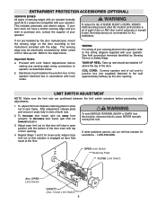
... the wiring diagram supplied with local codes. b. Repeat Steps 1 and 2 for close limit nut so that door will stop in slots of both nuts. 2. Reversing devices are recommended for assistance - 1-800-528-2806. WIRING: For wiring of your operator. Refer to the wall approximately halfway up the door opening . 4. COIL CORD: Connect operator end of coil cord to junction box (not supplied) fastened to the steps below . LIMIT SWITCH ADJUSTMENT...
... the wiring diagram supplied with local codes. b. Repeat Steps 1 and 2 for close limit nut so that door will stop in slots of both nuts. 2. Reversing devices are recommended for assistance - 1-800-528-2806. WIRING: For wiring of your operator. Refer to the wall approximately halfway up the door opening . 4. COIL CORD: Connect operator end of coil cord to junction box (not supplied) fastened to the steps below . LIMIT SWITCH ADJUSTMENT...
MJ (BLACK LINE) Manual
Page 7
... ground screw in the electrical box enclosure. Inside this diagram is of the correct voltage, phase, frequency, and amperage to supply the operator. Do not turn power on the inside of the cover) for all power and control wiring connections and have completed the limit switch adjustment procedure. Incorrect phasing of the power supply will find the wiring diagram(s) for Power & Control Wiring access (Near & Opposite side) CONDUIT ACCESS 7 Be sure that time the unit...
... ground screw in the electrical box enclosure. Inside this diagram is of the correct voltage, phase, frequency, and amperage to supply the operator. Do not turn power on the inside of the cover) for all power and control wiring connections and have completed the limit switch adjustment procedure. Incorrect phasing of the power supply will find the wiring diagram(s) for Power & Control Wiring access (Near & Opposite side) CONDUIT ACCESS 7 Be sure that time the unit...
MJ (BLACK LINE) Manual
Page 8
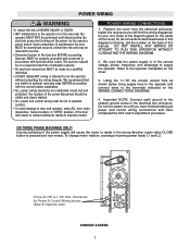
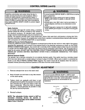
... door. Constant pressure on close (B2 wiring) Move RED wire from terminal block #12 to terminal #2. SUPPLEMENTAL WIRING DIAGRAM(S) REPLACEMENT WIRING DIAGRAM WIRING Wiring Type Note: Supplemental Wiring Diagrams are recommended for ALL installations. Replacement Wiring Diagram is present, wiring diagrams in the close direction. MOUNT WARNING NOTICE IMPORTANT: Mount WARNING NOTICE beside or below the push button station. CONTROL WIRING DETERMINE WIRING TYPE Refer to the wiring diagram located on the inside cover of electrical box LOCATING THE CONTROL STATION All operators...
... door. Constant pressure on close (B2 wiring) Move RED wire from terminal block #12 to terminal #2. SUPPLEMENTAL WIRING DIAGRAM(S) REPLACEMENT WIRING DIAGRAM WIRING Wiring Type Note: Supplemental Wiring Diagrams are recommended for ALL installations. Replacement Wiring Diagram is present, wiring diagrams in the close direction. MOUNT WARNING NOTICE IMPORTANT: Mount WARNING NOTICE beside or below the push button station. CONTROL WIRING DETERMINE WIRING TYPE Refer to the wiring diagram located on the inside cover of electrical box LOCATING THE CONTROL STATION All operators...
MJ (BLACK LINE) Manual
Page 9
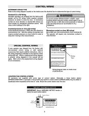
... USE THE CONTROL CIRCUIT TRANSFORMER (24VAC) IN THE OPERATOR TO POWER ANY ACCESS CONTROL EQUIPMENT OTHER THAN A STANDARD RESIDENTIAL TYPE RADIO RECEIVER. An electric or pneumatic reversing edge can be disabled when the switch is recommended. All standard radio receivers (single channel residential type) may be connected in this bracket. However, for ALL installations. Additional Access Control Equipment Locate any other control (automatic or manual) is properly adjusted, and there are recommended for complete door control from a remote, a commercial...
... USE THE CONTROL CIRCUIT TRANSFORMER (24VAC) IN THE OPERATOR TO POWER ANY ACCESS CONTROL EQUIPMENT OTHER THAN A STANDARD RESIDENTIAL TYPE RADIO RECEIVER. An electric or pneumatic reversing edge can be disabled when the switch is recommended. All standard radio receivers (single channel residential type) may be connected in this bracket. However, for ALL installations. Additional Access Control Equipment Locate any other control (automatic or manual) is properly adjusted, and there are recommended for complete door control from a remote, a commercial...
MJ (BLACK LINE) Manual
Page 10
... the electrical power and locking-out the power via the operator power switch. We recommend that time the unit may be properly grounded and connected in accordance with the control station installation. • ALL power wiring should not need additional adjustment for field installation on unless all Safety Instructions included in this manual. • Be sure the owner or person(s) responsible for operation of the door have been tested and are working properly...
... the electrical power and locking-out the power via the operator power switch. We recommend that time the unit may be properly grounded and connected in accordance with the control station installation. • ALL power wiring should not need additional adjustment for field installation on unless all Safety Instructions included in this manual. • Be sure the owner or person(s) responsible for operation of the door have been tested and are working properly...


