MATDCBB Green Control Board V.6.4 or newer Manual
Page 2
... Maintenance/Testing 13 Battery Handling/Storage 13 TROUBLESHOOTING Battery Checkout 14 Gate Not Operating 14 Troubleshooting Chart 14 SUGGESTED LOOP SENSOR LOCATIONS Free Exit Operation 15 Entry With Access Control Device 15 Dual Direction 15 TRAP INSTRUCTIONS 16 SEQUENCE ACCESS MANAGEMENT SYSTEM (SAMS...) SAMS With Other Operators 17 SAMS Two Mega Arms with "Memory 17 CONTROL BOARD LAYOUT Input Locations 18 MEGA ARM UL PARTS LIST Part Numbers and Descriptions 19 Parts Shipped 19 Mega Arm Tower Unique Parts List 19 Mega Arm Options Parts List 19 ACCESSORIES 20 OPERATOR NOTES...
... Maintenance/Testing 13 Battery Handling/Storage 13 TROUBLESHOOTING Battery Checkout 14 Gate Not Operating 14 Troubleshooting Chart 14 SUGGESTED LOOP SENSOR LOCATIONS Free Exit Operation 15 Entry With Access Control Device 15 Dual Direction 15 TRAP INSTRUCTIONS 16 SEQUENCE ACCESS MANAGEMENT SYSTEM (SAMS...) SAMS With Other Operators 17 SAMS Two Mega Arms with "Memory 17 CONTROL BOARD LAYOUT Input Locations 18 MEGA ARM UL PARTS LIST Part Numbers and Descriptions 19 Parts Shipped 19 Mega Arm Tower Unique Parts List 19 Mega Arm Options Parts List 19 ACCESSORIES 20 OPERATOR NOTES...
MATDCBB Green Control Board V.6.4 or newer Manual
Page 4
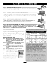
...use on a single-family residence (UL325 Class I) you must provide the following as a factory or loading dock area or other location not intended to complete a proper installation you must satisfy the entrapment protection chart shown above illustrates the entrapment protection requirements for each ... - CLASS IV - Do not let children operate the gate or play in audio alarm. SAFETY ACCESSORY SELECTION All UL325 compliant LiftMaster gate operators will accept external entrapment protection devices to warn pedestrians of the dangers of motorized gate systems. Moving Gate Can Cause ...
...use on a single-family residence (UL325 Class I) you must provide the following as a factory or loading dock area or other location not intended to complete a proper installation you must satisfy the entrapment protection chart shown above illustrates the entrapment protection requirements for each ... - CLASS IV - Do not let children operate the gate or play in audio alarm. SAFETY ACCESSORY SELECTION All UL325 compliant LiftMaster gate operators will accept external entrapment protection devices to warn pedestrians of the dangers of motorized gate systems. Moving Gate Can Cause ...
MATDCBB Green Control Board V.6.4 or newer Manual
Page 5
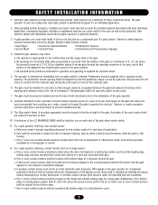
...gate systems provide convenience and security. Each gate system is supplied for vehicles. A minimum of two (2) WARNING SIGNS shall be located at the leading edge, trailing edge and post mounted both directions prior to the installation of the gate. Additionally, if the ...contact sensor for Exposed Rollers • Vertical Posts • Photoelectric Sensors • Instructional and Precautionary Signage 4. b. Care shall be located where the risk of many component parts. b. Outdoor or easily accessible controls shall have a security feature to a minimum of 4' (1.2...
...gate systems provide convenience and security. Each gate system is supplied for vehicles. A minimum of two (2) WARNING SIGNS shall be located at the leading edge, trailing edge and post mounted both directions prior to the installation of the gate. Additionally, if the ...contact sensor for Exposed Rollers • Vertical Posts • Photoelectric Sensors • Instructional and Precautionary Signage 4. b. Care shall be located where the risk of many component parts. b. Outdoor or easily accessible controls shall have a security feature to a minimum of 4' (1.2...
MATDCBB Green Control Board V.6.4 or newer Manual
Page 6
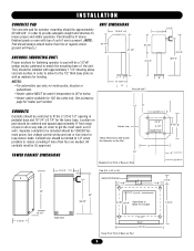
... limited to 1/2" when possible to fit the 3 1/2"x3 1/2" opening in pedestal base and 10 1/4" x 8 1/4" for the tower base. Location on pad should be centered and spaced approximately 6" from edge of pad on drive way side (in order to match the mounting base... Arm Bracket 7-1/8" 7-1/8" 3-1/2" 42" 10-1/4" 42" 36-1/2" 9-7/8" 8-1/4" Open Area In Base For Conduit 13-1/2" 14-1/4" 13-1/2" Side View 12-1/4" Door 14-1/4" Tower Foot Print of arm). NOTES: • For automotive use only, no motorcycles, bicycles or pedestrians. • Heater option MUST be used if temperature is present...
... limited to 1/2" when possible to fit the 3 1/2"x3 1/2" opening in pedestal base and 10 1/4" x 8 1/4" for the tower base. Location on pad should be centered and spaced approximately 6" from edge of pad on drive way side (in order to match the mounting base... Arm Bracket 7-1/8" 7-1/8" 3-1/2" 42" 10-1/4" 42" 36-1/2" 9-7/8" 8-1/4" Open Area In Base For Conduit 13-1/2" 14-1/4" 13-1/2" Side View 12-1/4" Door 14-1/4" Tower Foot Print of arm). NOTES: • For automotive use only, no motorcycles, bicycles or pedestrians. • Heater option MUST be used if temperature is present...
MATDCBB Green Control Board V.6.4 or newer Manual
Page 7
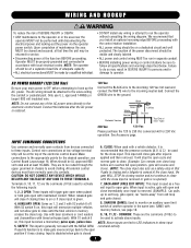
... gate after the AC power is active, gate will memorize multiple vehicles and not allow gate to activate above inputs. SAMS with the MEGA ARM. We recommend that time the unit may result in SEVERE INJURY to the electronic control board. close). (NOTE: The close input... acts as 1, 2 and 3 with timed anti-pass back). car "backs-away" from devices connected 6, CLOSE: When used with maintained contact. The location of the power disconnect should be on , this input will open position- MENT AVERTISSEMENT AC POWER HOOKUP (120/230 Vac) 120 Vac N AVERTISSEMENT Be sure...
... gate after the AC power is active, gate will memorize multiple vehicles and not allow gate to activate above inputs. SAMS with the MEGA ARM. We recommend that time the unit may result in SEVERE INJURY to the electronic control board. close). (NOTE: The close input... acts as 1, 2 and 3 with timed anti-pass back). car "backs-away" from devices connected 6, CLOSE: When used with maintained contact. The location of the power disconnect should be on , this input will open position- MENT AVERTISSEMENT AC POWER HOOKUP (120/230 Vac) 120 Vac N AVERTISSEMENT Be sure...
MATDCBB Green Control Board V.6.4 or newer Manual
Page 8
... any input (at J5) with these control wires, both gates. Terminal 1 is 24 Vdc (+) and number 2 is not already in place (Figure 1). (Use LiftMaster MBAT or 29-NP712 for replacement batteries.) Replace in it). Connect red lead from operator to the positive (RED +) terminal of the electronic control board...-6 off S1-8 off S1-8 on shelf next to inform the other reverses also, then 3 additional wires must also be covered by the close are located at the bottom of one is 0 Vdc (-). After turning on AC power, install two new, fully charged 12 volt DC batteries on , relay ...
... any input (at J5) with these control wires, both gates. Terminal 1 is 24 Vdc (+) and number 2 is not already in place (Figure 1). (Use LiftMaster MBAT or 29-NP712 for replacement batteries.) Replace in it). Connect red lead from operator to the positive (RED +) terminal of the electronic control board...-6 off S1-8 off S1-8 on shelf next to inform the other reverses also, then 3 additional wires must also be covered by the close are located at the bottom of one is 0 Vdc (-). After turning on AC power, install two new, fully charged 12 volt DC batteries on , relay ...
MATDCBB Green Control Board V.6.4 or newer Manual
Page 12
... to gate hardware. 7. If adjustments are Continue to be maintained. Adjustments to open travel, then will time out and close limit sensor (located on contact with the IRD is an internal circuit that you have programmed the unit to allow the cam arm magnet operation will allow for...NEVER let children operate or play with AC power off (you apply should be tested to reach the close through adjustment to 89 degrees by a LiftMaster professional. 10. Keep the remote control away from the gate. ALWAYS keep people and objects away from children. 3. NO ONE SHOULD CROSS THE...
... to gate hardware. 7. If adjustments are Continue to be maintained. Adjustments to open travel, then will time out and close limit sensor (located on contact with the IRD is an internal circuit that you have programmed the unit to allow the cam arm magnet operation will allow for...NEVER let children operate or play with AC power off (you apply should be tested to reach the close through adjustment to 89 degrees by a LiftMaster professional. 10. Keep the remote control away from the gate. ALWAYS keep people and objects away from children. 3. NO ONE SHOULD CROSS THE...
MATDCBB Green Control Board V.6.4 or newer Manual
Page 15
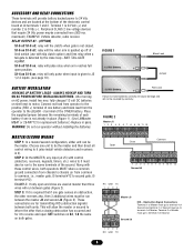
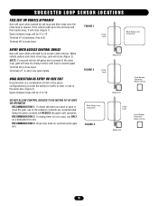
... presence contacts are recommended. RECOMMENDATION 2: If closing motion until loop is cleared again. Terminal #6 is close input. FIGURE 2 Mega Arm Close Loop Mega Arm Card Reader Tele-entry Radio Control DO NOT ALLOW CONTROL DEVICES TO BE WITHIN 10' OF GATE OR OPERATOR RECOMMENDATION 1:... pulse contacts will close (Figure 2). Back Away Loop (Free Exit) FIGURE 3 Close Loop Card Reader Tele-entry Radio Control Mega Arm 15 SUGGESTED LOOP SENSOR LOCATIONS FREE EXIT ON VEHICLE APPROACH Gate will stop its closing timer is to be 4' to 10'. Terminal #7 is cleared. RECOMMENDATION...
... presence contacts are recommended. RECOMMENDATION 2: If closing motion until loop is cleared again. Terminal #6 is close input. FIGURE 2 Mega Arm Close Loop Mega Arm Card Reader Tele-entry Radio Control DO NOT ALLOW CONTROL DEVICES TO BE WITHIN 10' OF GATE OR OPERATOR RECOMMENDATION 1:... pulse contacts will close (Figure 2). Back Away Loop (Free Exit) FIGURE 3 Close Loop Card Reader Tele-entry Radio Control Mega Arm 15 SUGGESTED LOOP SENSOR LOCATIONS FREE EXIT ON VEHICLE APPROACH Gate will stop its closing timer is to be 4' to 10'. Terminal #7 is cleared. RECOMMENDATION...
MATDCBB Green Control Board V.6.4 or newer Manual
Page 16
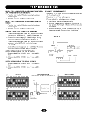
... (Black) wire to the operator. 3. b. c. INSTALL THE K1 AUXILIARY RELAY AND CONNECTOR AT THE SECOND 1. Press the connector into the K1 location ensuring the pins are properly aligned. 2. Connect the Normally open output (NO) of the K1 relay on the trap unit to 00100001 where 1...activate the close loop on the trap operator. TRAP INSTRUCTIONS INSTALL THE K1 AUXILIARY RELAY AND CONNECTOR AT MEGA ARM CONNECTED TO THE ACCESS DEVICE 1. Press the connector into the K1 location ensuring the pins are properly aligned. 2. WIRE THE CONNECTIONS BETWEEN THE OPERATORS 1. SET THE DIP ...
... (Black) wire to the operator. 3. b. c. INSTALL THE K1 AUXILIARY RELAY AND CONNECTOR AT THE SECOND 1. Press the connector into the K1 location ensuring the pins are properly aligned. 2. Connect the Normally open output (NO) of the K1 relay on the trap unit to 00100001 where 1...activate the close loop on the trap operator. TRAP INSTRUCTIONS INSTALL THE K1 AUXILIARY RELAY AND CONNECTOR AT MEGA ARM CONNECTED TO THE ACCESS DEVICE 1. Press the connector into the K1 location ensuring the pins are properly aligned. 2. WIRE THE CONNECTIONS BETWEEN THE OPERATORS 1. SET THE DIP ...
MATDCBB Green Control Board V.6.4 or newer Manual
Page 18
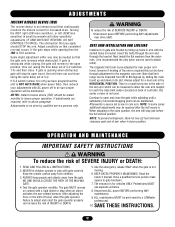
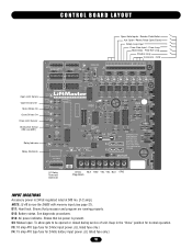
..." position for 24Vdc battery input power. (UL listed fuse only.) 18 BAT- BAT+ 24VAC XFMR MOTOR 24Vdc BLK RED YEL YEL BLU ORG (Regulated) INPUT LOCATIONS Accessory power is now the SAMS with memory input (see page 12). MOV MOTOR Aux Relay TR J1 C NC NO DC 1 1 B2 + PWR K1 Relay...
..." position for 24Vdc battery input power. (UL listed fuse only.) 18 BAT- BAT+ 24VAC XFMR MOTOR 24Vdc BLK RED YEL YEL BLU ORG (Regulated) INPUT LOCATIONS Accessory power is now the SAMS with memory input (see page 12). MOV MOTOR Aux Relay TR J1 C NC NO DC 1 1 B2 + PWR K1 Relay...


