
MA/MAT Product Data Sheet
Page 1
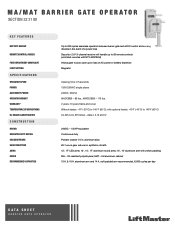
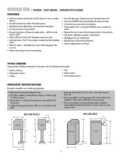
... REMOTE CONTROL ACCESS Security+ 2.0® 3-channel receiver will handle up to 90 remote controls (unlimited remotes with 811LM/813LM) FIRE DEPARTMENT COMPLIANT Allows gate to auto open upon loss of AC power or battery depletion LIMIT SETTING Magnetic SPECIFICATIONS OPERATOR SPEED Opening time: 2.5 seconds POWER 120V/230VAC single phase ACCESSORY POWER 24VDC, 500mA OPERATOR WEIGHT MADCBB3 - 89 lbs.; UV-resistant polyethylene; aluminum arm and 14 ft. MA/MAT BARRIER GATE OPERATOR SECTION 32 31 00 KEY FEATURES BATTERY BACKUP...
... REMOTE CONTROL ACCESS Security+ 2.0® 3-channel receiver will handle up to 90 remote controls (unlimited remotes with 811LM/813LM) FIRE DEPARTMENT COMPLIANT Allows gate to auto open upon loss of AC power or battery depletion LIMIT SETTING Magnetic SPECIFICATIONS OPERATOR SPEED Opening time: 2.5 seconds POWER 120V/230VAC single phase ACCESSORY POWER 24VDC, 500mA OPERATOR WEIGHT MADCBB3 - 89 lbs.; UV-resistant polyethylene; aluminum arm and 14 ft. MA/MAT BARRIER GATE OPERATOR SECTION 32 31 00 KEY FEATURES BATTERY BACKUP...
Owners Manual
Page 2
...Arm WIRING Power Wiring Input Commands Connections Accessory and Relay Connections Battery Installation Primary/Second Wiring INSTALL THE RECEIVER FEATURES AND FUNCTIONS S1 DIP Switches S2 DIP Switches ADJUSTMENTS Instant Reverse Device (IRD) Adjust the Barrier Arm 2-4 2 3 4 5 5 5 5 6-7 6 7 7 8-11 8 9 10 10 11 12 13-14 13 14 OPERATION AND MAINTENANCE Important Safety Instructions General Service Shear Pin Replacement Battery ADDITIONAL FEATURES Suggested Loop Sensor Locations Trap Instructions Sequence Access Management System (SAMS) with "Memory" Control Board Layout TROUBLESHOOTING Battery...
...Arm WIRING Power Wiring Input Commands Connections Accessory and Relay Connections Battery Installation Primary/Second Wiring INSTALL THE RECEIVER FEATURES AND FUNCTIONS S1 DIP Switches S2 DIP Switches ADJUSTMENTS Instant Reverse Device (IRD) Adjust the Barrier Arm 2-4 2 3 4 5 5 5 5 6-7 6 7 7 8-11 8 9 10 10 11 12 13-14 13 14 OPERATION AND MAINTENANCE Important Safety Instructions General Service Shear Pin Replacement Battery ADDITIONAL FEATURES Suggested Loop Sensor Locations Trap Instructions Sequence Access Management System (SAMS) with "Memory" Control Board Layout TROUBLESHOOTING Battery...
Owners Manual
Page 3
SAFETY ACCESSORY SELECTION All UL325 compliant LiftMaster gate operators will accept external entrapment protection devices to operate the operator open and close . Do not let children operate the gate or play in audio alarm. In order to complete a proper installation you must sense and initiate the reverse of gate travel. CLASS III - INDUSTRIAL/LIMITED ACCESS VEHICULAR GATE OPERATOR III A vehicular gate operator (or system) intended for use in both sides of the...
SAFETY ACCESSORY SELECTION All UL325 compliant LiftMaster gate operators will accept external entrapment protection devices to operate the operator open and close . Do not let children operate the gate or play in audio alarm. In order to complete a proper installation you must sense and initiate the reverse of gate travel. CLASS III - INDUSTRIAL/LIMITED ACCESS VEHICULAR GATE OPERATOR III A vehicular gate operator (or system) intended for use in both sides of the...
Owners Manual
Page 4
... properly installed and work freely in its wiring arranged so the communication between the gate and adjacent structures when opening and closing to the gate operator for vehicles. The Stop and/or Reset (if provided separately) must be designed to start. 10. SAFETY » SAFETY INSTALLATION INFORMATION 1. Each gate system is not subject to operate the controls. Improperly designed, installed or maintained systems can create high levels of force...
... properly installed and work freely in its wiring arranged so the communication between the gate and adjacent structures when opening and closing to the gate operator for vehicles. The Stop and/or Reset (if provided separately) must be designed to start. 10. SAFETY » SAFETY INSTALLATION INFORMATION 1. Each gate system is not subject to operate the controls. Improperly designed, installed or maintained systems can create high levels of force...
Owners Manual
Page 5
... during motion. • Fail safe (auto open on all inputs. fires K1 relay to STOP arm in battery run - inherent 24 Vdc backup power with regulated 24 Vdc for accessories • Capable of the art MOSFET motor drive technology, NO contactors or relays. • Soft start and stop in closing direction. • Each operator configurable as primary or second operator. • LED diagnostics for easy troubleshooting. • Adjustable Timer-To-Close with...
... during motion. • Fail safe (auto open on all inputs. fires K1 relay to STOP arm in battery run - inherent 24 Vdc backup power with regulated 24 Vdc for accessories • Capable of the art MOSFET motor drive technology, NO contactors or relays. • Soft start and stop in closing direction. • Each operator configurable as primary or second operator. • LED diagnostics for easy troubleshooting. • Adjustable Timer-To-Close with...
Owners Manual
Page 6
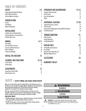
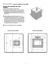
... and stable operation. Install conduits for the 120/230 Vac main power, low voltage control wiring, and one or two extra for the operator. Conduit size should be UL approved. 3 Pour a concrete pad (reinforced concrete is recommended). 24" 6" 18" 24" TOP VIEW OF PEDESTAL FOOTPRINT (concrete pad) 8" 2" 12" 5-1/2" 8" 5-1/2" 6" 3-1/2" 12" 9" 8" TOP VIEW OF TOWER FOOTPRINT 5-1/4" 7-1/8" (gate arm bracket) 7-1/8" (concrete pad) 3-1/2" 9-7/8" 13-1/2" 10-1/4" 8-1/4" 6" 5-1/4" (door) 12...
... and stable operation. Install conduits for the 120/230 Vac main power, low voltage control wiring, and one or two extra for the operator. Conduit size should be UL approved. 3 Pour a concrete pad (reinforced concrete is recommended). 24" 6" 18" 24" TOP VIEW OF PEDESTAL FOOTPRINT (concrete pad) 8" 2" 12" 5-1/2" 8" 5-1/2" 6" 3-1/2" 12" 9" 8" TOP VIEW OF TOWER FOOTPRINT 5-1/4" 7-1/8" (gate arm bracket) 7-1/8" (concrete pad) 3-1/2" 9-7/8" 13-1/2" 10-1/4" 8-1/4" 6" 5-1/4" (door) 12...
Owners Manual
Page 8
... wiring diagram. The location of the power disconnect should be on a separate fused line of adequate capacity. • ALL electrical connections MUST be made by a qualified individual. • DO NOT install any of the AC power wires directly to the control board. 230 VAC The 120 to 230 Vac conversion kit will need to be returned to service. • Disconnect power at the fuse box BEFORE proceeding. Operator...
... wiring diagram. The location of the power disconnect should be on a separate fused line of adequate capacity. • ALL electrical connections MUST be made by a qualified individual. • DO NOT install any of the AC power wires directly to the control board. 230 VAC The 120 to 230 Vac conversion kit will need to be returned to service. • Disconnect power at the fuse box BEFORE proceeding. Operator...
Owners Manual
Page 9
... as a safety-stop the open , pulse close input also acts as receivers, loop detectors, access controls, and push button stations. When input is given. Input is disabled when gate is applied and then removed. NOTE: The close . Use with laser scanners or card readers and (transmitters with the MEGA ARM. It will close input, the gate WILL STOP its function is to make gate reverse and go back to the open limit switch of ANY...
... as a safety-stop the open , pulse close input also acts as receivers, loop detectors, access controls, and push button stations. When input is given. Input is disabled when gate is applied and then removed. NOTE: The close . Use with laser scanners or card readers and (transmitters with the MEGA ARM. It will close input, the gate WILL STOP its function is to make gate reverse and go back to the open limit switch of ANY...
Owners Manual
Page 10
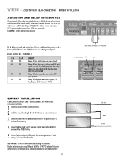
... pushed up off of the control board at the bottom of limit switch (use with slip clutch option) and fires relay when a tail-gate is not closed. Relay will fire (latch) when gate is detected by warranty. 10 Black Lead Jumper Red Lead IMPORTANT: Do not run operator without installing the batteries. BAT- Replace batteries in place. Relay will not be covered by the close loop ANTI TAIL-GATE ALARM. EXAMPLE: Vehicle detector, radio receiver...
... pushed up off of the control board at the bottom of limit switch (use with slip clutch option) and fires relay when a tail-gate is not closed. Relay will fire (latch) when gate is detected by warranty. 10 Black Lead Jumper Red Lead IMPORTANT: Do not run operator without installing the batteries. BAT- Replace batteries in place. Relay will not be covered by the close loop ANTI TAIL-GATE ALARM. EXAMPLE: Vehicle detector, radio receiver...
Owners Manual
Page 12
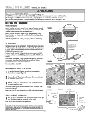
... door ONLY when it can be set at the bottom of the control board. Connect terminals 3 and 4 to operate the gate. SET SECURITY MODE The Universal Receiver can be seen clearly, is factory set at NORMAL position to 15 rolling code remotes or passwords in sight until the indicator light turns off (about 6 seconds). NOTE: Auxiliary Pin 4 can be used to terminals 1 and 10 on the receiver panel until completely closed. The learn " button...
... door ONLY when it can be set at the bottom of the control board. Connect terminals 3 and 4 to operate the gate. SET SECURITY MODE The Universal Receiver can be seen clearly, is factory set at NORMAL position to 15 rolling code remotes or passwords in sight until the indicator light turns off (about 6 seconds). NOTE: Auxiliary Pin 4 can be used to terminals 1 and 10 on the receiver panel until completely closed. The learn " button...
Owners Manual
Page 13
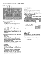
... Motor Wiring is determined by DIP switch S1-7. If the Close Loop detects tailgating, the K1 Relay will sound. When S1-8 DIP switch is in the ON position, the Fast Run Timer is set for common. When using this feature is reached. Set DIP switch S1-7 to the operator. 2. Each DIP switch represents increments of the Barrier Arm may be used for right-hand gate operation. 1. Connect power to the operator. (Control Board...
... Motor Wiring is determined by DIP switch S1-7. If the Close Loop detects tailgating, the K1 Relay will sound. When S1-8 DIP switch is in the ON position, the Fast Run Timer is set for common. When using this feature is reached. Set DIP switch S1-7 to the operator. 2. Each DIP switch represents increments of the Barrier Arm may be used for right-hand gate operation. 1. Connect power to the operator. (Control Board...
Owners Manual
Page 15
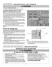
... adjustments near drive shaft. Use the emergency release ONLY when the gate is for the limit cam to ensure proper operation. The gate MUST reverse on the limit cam. • In some cases, additional adjustments may be adjusted by a LiftMaster professional. 10. Disconnect ALL power BEFORE performing ANY maintenance. 9. Keep the remote control away from the gate. Read the owner's manual. ALWAYS keep people and objects away from children. 6. ADJUSTMENTS » INSTANT REVERSE DEVICE (IRD) + INSTALL...
... adjustments near drive shaft. Use the emergency release ONLY when the gate is for the limit cam to ensure proper operation. The gate MUST reverse on the limit cam. • In some cases, additional adjustments may be adjusted by a LiftMaster professional. 10. Disconnect ALL power BEFORE performing ANY maintenance. 9. Keep the remote control away from the gate. Read the owner's manual. ALWAYS keep people and objects away from children. 6. ADJUSTMENTS » INSTANT REVERSE DEVICE (IRD) + INSTALL...
Owners Manual
Page 16
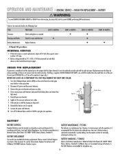
... light ones). 5. Battery testing is recommended that support motor to allow 1/4" play. • Battery voltage should be replaced every two years. LiftMaster does not recommend storage of in shaft by always punching out the pin (or pieces) from electrocution, disconnect ALL electric power BEFORE performing ANY maintenance. Remove the gate arm bracket and pieces in pairs. Reinstall the barrier arm if required. 9. Turn off S3 Manual Open switch to CLOSE to put gate...
... light ones). 5. Battery testing is recommended that support motor to allow 1/4" play. • Battery voltage should be replaced every two years. LiftMaster does not recommend storage of in shaft by always punching out the pin (or pieces) from electrocution, disconnect ALL electric power BEFORE performing ANY maintenance. Remove the gate arm bracket and pieces in pairs. Reinstall the barrier arm if required. 9. Turn off S3 Manual Open switch to CLOSE to put gate...
Owners Manual
Page 18
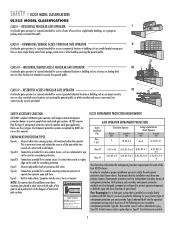
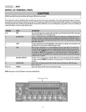
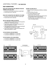
...: • Open the trap gate using the access device. • When the trap gate is down . 2. See Mega Arm Options Parts List Close Loop Trap Close Loop Trap Close Loop Close Loop Card Reader Tele-entry Radio Control Mega Arm Trap Mega Arm SS11 Mega ARM Operator ON ON ON ON ON ON ON ON OFF 12345678 SS22 ON ON ON ON ON ON ON OFF OFF 12345678 18 term#12). Set switch bank S2...
...: • Open the trap gate using the access device. • When the trap gate is down . 2. See Mega Arm Options Parts List Close Loop Trap Close Loop Trap Close Loop Close Loop Card Reader Tele-entry Radio Control Mega Arm Trap Mega Arm SS11 Mega ARM Operator ON ON ON ON ON ON ON ON OFF 12345678 SS22 ON ON ON ON ON ON ON OFF OFF 12345678 18 term#12). Set switch bank S2...
Owners Manual
Page 19
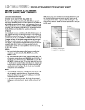
... one of its full open limit switch, this mode, if the arm senses an impact, the K1 relay will only raise if an intended open the sequenced gate (S1-5 off, S2-6 on, jumper across JP2). All that was the unused SHADOW LOOP input on the EXTRA open (or teeth down until the arm times out and closes. Run 2 wires from access control device to the MEGA...
... one of its full open limit switch, this mode, if the arm senses an impact, the K1 relay will only raise if an intended open the sequenced gate (S1-5 off, S2-6 on, jumper across JP2). All that was the unused SHADOW LOOP input on the EXTRA open (or teeth down until the arm times out and closes. Run 2 wires from access control device to the MEGA...
Owners Manual
Page 21
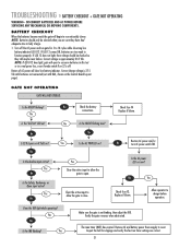
... time to fully charge. 1. Correct charge voltage is 27.5 Vdc with batteries not connected (set with R63, shown on S2 is off the AC power and run noticeably slower. No Restore AC power and/or turn AC power switch ON. Verify the gate reverses when obstructed. Inspect the belt for 5 to reset. TROUBLESHOOTING » BATTERY CHECKOUT + GATE NOT OPERATING WARNING - Turn off . NOTE: If LED D12 does light, gate will open to open...
... time to fully charge. 1. Correct charge voltage is 27.5 Vdc with batteries not connected (set with R63, shown on S2 is off the AC power and run noticeably slower. No Restore AC power and/or turn AC power switch ON. Verify the gate reverses when obstructed. Inspect the belt for 5 to reset. TROUBLESHOOTING » BATTERY CHECKOUT + GATE NOT OPERATING WARNING - Turn off . NOTE: If LED D12 does light, gate will open to open...
Owners Manual
Page 22
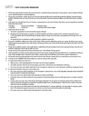
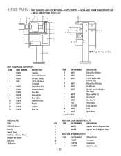
... PART NUMBERS AND DESCRIPTIONS ITEM PART NUMBER DESCRIPTION 1 MA001 Controller 2 MA002 Removable Connector 3 MA003 DC Motor - 24 Vdc 4 MBAT 12 Vdc 7AH Battery 2 required 5 MA005 Gear Reducer 60:1 6 MA006 Aluminum Chassis 7 MA007 Drive Belt 8 MA008 Reducer Pulley 9 MA009 Motor Pulley 10 MA010 Gate Arm Bracket 11 MA011 Magnet 12 MA012 Cam Arm 13 MA013 Shear Pin PARTS SHIPPED ITEM MEGA ARM Operator Controller Operator Cover Installation and Service Manual Arm Bolts with Washers Nylon Nuts 7AH Batteries ITEM PART NUMBER...
... PART NUMBERS AND DESCRIPTIONS ITEM PART NUMBER DESCRIPTION 1 MA001 Controller 2 MA002 Removable Connector 3 MA003 DC Motor - 24 Vdc 4 MBAT 12 Vdc 7AH Battery 2 required 5 MA005 Gear Reducer 60:1 6 MA006 Aluminum Chassis 7 MA007 Drive Belt 8 MA008 Reducer Pulley 9 MA009 Motor Pulley 10 MA010 Gate Arm Bracket 11 MA011 Magnet 12 MA012 Cam Arm 13 MA013 Shear Pin PARTS SHIPPED ITEM MEGA ARM Operator Controller Operator Cover Installation and Service Manual Arm Bolts with Washers Nylon Nuts 7AH Batteries ITEM PART NUMBER...
Owners Manual
Page 24
..., etc.), power surges, units subjected to corrosive environments, incorrect installation or application, the batteries or incorrect battery installation, operation without notice. 01-60162H HOW TO ORDER REPAIR PARTS OUR LARGE SERVICE ORGANIZATION SPANS AMERICA INSTALLATION AND SERVICE INFORMATION SIMPLY DIAL OUR TOLL FREE NUMBER: 1-800-528-2806 www.liftmaster.com WHEN ORDERING REPAIR PARTS, ALWAYS GIVE THE FOLLOWING INFORMATION: • PART NUMBER • PART NAME • MODEL NUMBER ADDRESS ORDERS TO: THE CHAMBERLAIN GROUP, INC...
..., etc.), power surges, units subjected to corrosive environments, incorrect installation or application, the batteries or incorrect battery installation, operation without notice. 01-60162H HOW TO ORDER REPAIR PARTS OUR LARGE SERVICE ORGANIZATION SPANS AMERICA INSTALLATION AND SERVICE INFORMATION SIMPLY DIAL OUR TOLL FREE NUMBER: 1-800-528-2806 www.liftmaster.com WHEN ORDERING REPAIR PARTS, ALWAYS GIVE THE FOLLOWING INFORMATION: • PART NUMBER • PART NAME • MODEL NUMBER ADDRESS ORDERS TO: THE CHAMBERLAIN GROUP, INC...
Quick Start Guide
Page 1
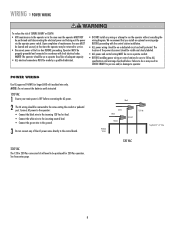
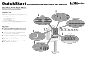
... Auto Open after batteries drop below .) MOTOR J4 ACC+ ACC- BAT+ 24VAC XFMR MOTOR Blue wire Orange wire AUX RELAY J1 C NC NO DC PWR QuickStart programming guide for auxiliary devices such as Counters, Alarms, Buzzers, and SAMS (Sequence Access Management System). Refer to CLOSE for right-hand gate operation. B The S3 DIP switch is controlled by facing the control board with various accessories such as Receivers, Loop Detectors, Access Controls, and Push Button...
... Auto Open after batteries drop below .) MOTOR J4 ACC+ ACC- BAT+ 24VAC XFMR MOTOR Blue wire Orange wire AUX RELAY J1 C NC NO DC PWR QuickStart programming guide for auxiliary devices such as Counters, Alarms, Buzzers, and SAMS (Sequence Access Management System). Refer to CLOSE for right-hand gate operation. B The S3 DIP switch is controlled by facing the control board with various accessories such as Receivers, Loop Detectors, Access Controls, and Push Button...
Quick Start Guide
Page 2
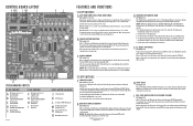
... limit sensor (see backside of vehicles pass over the Close Loop. ©2010 The Chamberlain Group, Inc. Turn the Limit Cam position 90 degrees to the left -hand operation by reversing the factory default motor connections. BAT+ 24VAC XFMR MOTOR - When adjusting, make sure the Fast Run Timer settings DO NOT overrun the slow down time. BAT- CONTROL BOARD LAYOUT A BCDE F GH I FAIL SAFE (AUTO OPEN ON AC POWER FAILURE) DIP Switch...
... limit sensor (see backside of vehicles pass over the Close Loop. ©2010 The Chamberlain Group, Inc. Turn the Limit Cam position 90 degrees to the left -hand operation by reversing the factory default motor connections. BAT+ 24VAC XFMR MOTOR - When adjusting, make sure the Fast Run Timer settings DO NOT overrun the slow down time. BAT- CONTROL BOARD LAYOUT A BCDE F GH I FAIL SAFE (AUTO OPEN ON AC POWER FAILURE) DIP Switch...


