"Manufacturer's Certification for Credit" Manual
Page 1
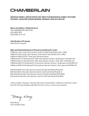
...LiftMaster LA412 Solar Gate Operator System (Single Gate Model LA412-1PKG) LiftMaster LA412 Solar Gate Operator System (Dual Gate Model LA412-2PKG) LiftMaster SW425DCSP3 Solar Gate Operator System LiftMaster RSL12V Residential DC Slide Gate Operator System ( Single gate model RSL12V) LiftMaster RSL12V Residential DC Slide Gate Operator System ( Dual gate model RSL12V) LiftMaster RSW12V Residential DC Swing Gate Operator System ( Single gate model RSW12V) LiftMaster RSW12V Residential DC Swing Gate Operator System ( Dual gate model RSW12V) Elite RoboSlide Solar Gate Operator System (Single Gate...
...LiftMaster LA412 Solar Gate Operator System (Single Gate Model LA412-1PKG) LiftMaster LA412 Solar Gate Operator System (Dual Gate Model LA412-2PKG) LiftMaster SW425DCSP3 Solar Gate Operator System LiftMaster RSL12V Residential DC Slide Gate Operator System ( Single gate model RSL12V) LiftMaster RSL12V Residential DC Slide Gate Operator System ( Dual gate model RSL12V) LiftMaster RSW12V Residential DC Swing Gate Operator System ( Single gate model RSW12V) LiftMaster RSW12V Residential DC Swing Gate Operator System ( Dual gate model RSW12V) Elite RoboSlide Solar Gate Operator System (Single Gate...

Refer to the solar cycle chart for more details. Manual
Page 1
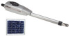
... where temperatures reach below 32°F (and above -4°F) for the entire day. LA412 not supported/available in an open area clear of the country. Power is for operating a gate while minimizing power consumption at all other times. The number of solar panels required is ... hours of sunlight during the winter months. Low power draw or Wireless Accessories are recommended in the given regions. LA412 Solar Gate Access System Daily Cycle Chart The LA412 Solar Gate Access System utilizes the innovative EverCharge® Power Management System to the gate operator via batteries.
... where temperatures reach below 32°F (and above -4°F) for the entire day. LA412 not supported/available in an open area clear of the country. Power is for operating a gate while minimizing power consumption at all other times. The number of solar panels required is ... hours of sunlight during the winter months. Low power draw or Wireless Accessories are recommended in the given regions. LA412 Solar Gate Access System Daily Cycle Chart The LA412 Solar Gate Access System utilizes the innovative EverCharge® Power Management System to the gate operator via batteries.

LA412 Manual
Page 1
LA412 & LA412-S 12 VOLT DC SOLAR RESIDENTIAL SWING GATE OPERATOR OWNER'S MANUAL MeBtOoLaaxplrtC(giXooennLMatrl)ol FOR RESIDENTIAL USE ONLY ■ Please read this manual and the enclosed safety materials carefully! ■ Periodic checks of the operator by a qualified technician are required to ensure safe operation. ■ The model number is located inside the control box of your operator. ■ Serial # ■ Installation date 2 YEAR WARRANTY
LA412 & LA412-S 12 VOLT DC SOLAR RESIDENTIAL SWING GATE OPERATOR OWNER'S MANUAL MeBtOoLaaxplrtC(giXooennLMatrl)ol FOR RESIDENTIAL USE ONLY ■ Please read this manual and the enclosed safety materials carefully! ■ Periodic checks of the operator by a qualified technician are required to ensure safe operation. ■ The model number is located inside the control box of your operator. ■ Serial # ■ Installation date 2 YEAR WARRANTY
LA412 Manual
Page 2
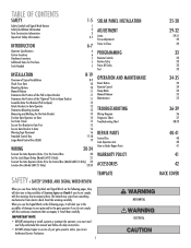
... 14 15 15 16 16 17-18 19 WIRING 20-24 Connect the Gate Operator (Gate 1) to the Control Box 20 Set the Lock/Bipart Delay (Model LA412-S Only) 21 Connect the Gate Operator (Gate 2) to the Control Box (Model LA412-S Only) 22 Junction Box (Model LA412-S Only) 23-24 SOLAR PANEL INSTALLATION ADJUSTMENT Limits Force Adjustment Timer-to...
... 14 15 15 16 16 17-18 19 WIRING 20-24 Connect the Gate Operator (Gate 1) to the Control Box 20 Set the Lock/Bipart Delay (Model LA412-S Only) 21 Connect the Gate Operator (Gate 2) to the Control Box (Model LA412-S Only) 22 Junction Box (Model LA412-S Only) 23-24 SOLAR PANEL INSTALLATION ADJUSTMENT Limits Force Adjustment Timer-to...
LA412 Manual
Page 3
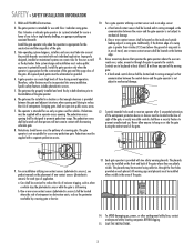
... the gate. 9. a. The gate operator is appropriate for the construction of the gate and the usage class of the gate. 3. Install the gate operator only when the operator is intended for use with a separate pedestrian access. 10. Install the gate operator only when the operator is ...placards may be eliminated or guarded. 4. SAVE THE INSTRUCTIONS. 2 Class I vehicular swing gates. Gate operating system designers, installers and users must be mounted using cable ties through the gate to the installation of nuisance tripping, such as the perimeter reachable by a moving . All...
... the gate. 9. a. The gate operator is appropriate for the construction of the gate and the usage class of the gate. 3. Install the gate operator only when the operator is intended for use with a separate pedestrian access. 10. Install the gate operator only when the operator is ...placards may be eliminated or guarded. 4. SAVE THE INSTRUCTIONS. 2 Class I vehicular swing gates. Gate operating system designers, installers and users must be mounted using cable ties through the gate to the installation of nuisance tripping, such as the perimeter reachable by a moving . All...
LA412 Manual
Page 4
... such stops shall horizontally or vertically project no more than 16 inches (406 mm), refer to ASTM F2200 for exception. 4.2 Class IV vehicular horizontal swing gates shall be designed, constructed and installed in accordance with a powered gate operator. 3.2 The following provisions shall apply to Class 1, Class II and Class III vehicular horizontal swing...
... such stops shall horizontally or vertically project no more than 16 inches (406 mm), refer to ASTM F2200 for exception. 4.2 Class IV vehicular horizontal swing gates shall be designed, constructed and installed in accordance with a powered gate operator. 3.2 The following provisions shall apply to Class 1, Class II and Class III vehicular horizontal swing...
LA412 Manual
Page 6
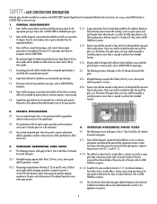
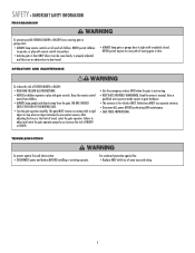
... and electrocution: • DISCONNECT power and battery BEFORE installing or servicing operator. SAFETY » IMPORTANT SAFETY INFORMATION PROGRAMMING To prevent possible SERIOUS INJURY or DEATH from a moving . • KEEP GATES PROPERLY MAINTAINED. NEVER permit children to door travel , retest the gate operator. The gate MUST reverse on contact with fuse of SEVERE INJURY or DEATH...
... and electrocution: • DISCONNECT power and battery BEFORE installing or servicing operator. SAFETY » IMPORTANT SAFETY INFORMATION PROGRAMMING To prevent possible SERIOUS INJURY or DEATH from a moving . • KEEP GATES PROPERLY MAINTAINED. NEVER permit children to door travel , retest the gate operator. The gate MUST reverse on contact with fuse of SEVERE INJURY or DEATH...
LA412 Manual
Page 7
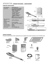
... must use separate entrance Warning Signs (2) Wire Nuts (6) Model LA412 ONLY Watertight Connector Model LA412-S ONLY (2) Gate Operator Model LA412 (1) Model LA412-S (2) Extension Cable Model LA412-S ONLY 6 Junction Box Model LA412-S ONLY This entrance is required. Pull-to-Open Bracket Model LA412 (1) Model LA412-S (2) Gate Bracket Model LA412 (1) Model LA412-S (2) Post Bracket Model LA412 (1) Model LA412-S (2) 12V 10W Solar Panel Model SOLPNL10W12V (1) Cable Ties (4) Standard...
... must use separate entrance Warning Signs (2) Wire Nuts (6) Model LA412 ONLY Watertight Connector Model LA412-S ONLY (2) Gate Operator Model LA412 (1) Model LA412-S (2) Extension Cable Model LA412-S ONLY 6 Junction Box Model LA412-S ONLY This entrance is required. Pull-to-Open Bracket Model LA412 (1) Model LA412-S (2) Gate Bracket Model LA412 (1) Model LA412-S (2) Post Bracket Model LA412 (1) Model LA412-S (2) 12V 10W Solar Panel Model SOLPNL10W12V (1) Cable Ties (4) Standard...
LA412 Manual
Page 11
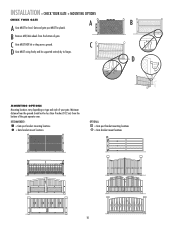
... locations vary depending on type and style of gate. C D Gate MUST swing freely and be plumb. INSTALLATION » CHECK YOUR GATE + MOUNTING OPTIONS CHECK YOUR GATE A B A Gate MUST be less than 4 inches (10.2 cm) from the bottom of your gate. B Remove ANY/ALL wheels from the bottom of the gate operator arm. Minimum distance from the ground should...
... locations vary depending on type and style of gate. C D Gate MUST swing freely and be plumb. INSTALLATION » CHECK YOUR GATE + MOUNTING OPTIONS CHECK YOUR GATE A B A Gate MUST be less than 4 inches (10.2 cm) from the bottom of your gate. B Remove ANY/ALL wheels from the bottom of the gate operator arm. Minimum distance from the ground should...
LA412 Manual
Page 13
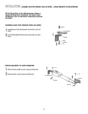
... Bracket PPoostsBtrBacrkaectket WWaashsehrer LLoockckWaWshaesr her NNuut t ATTACH BRACKETS TO GATE OPERATOR 1 Attach post bracket assembly to operator using pins and hairpin clips. 2 Attach gate bracket to -open bracket on the following pages display a typical Left-Hand Gate installation. ASSEMBLE GATE POST BRACKET (PULL-TO-OPEN) 1 Assemble gate post bracket by placing pull-to-open kit 50-19503...
... Bracket PPoostsBtrBacrkaectket WWaashsehrer LLoockckWaWshaesr her NNuut t ATTACH BRACKETS TO GATE OPERATOR 1 Attach post bracket assembly to operator using pins and hairpin clips. 2 Attach gate bracket to -open bracket on the following pages display a typical Left-Hand Gate installation. ASSEMBLE GATE POST BRACKET (PULL-TO-OPEN) 1 Assemble gate post bracket by placing pull-to-open kit 50-19503...
LA412 Manual
Page 15
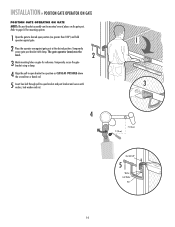
... greater than 100°) and hold operator against gate. 2 Place the operator arm against gate post at the desired position. Temporarily secure gate post bracket with washer, lock washer and nut. 1 3 4 7" (18 cm) 7" (18 cm) Hex Bolt 3/8" 5 Washer Lock Washer Nut 14 INSTALLATION » POSITION GATE OPERATOR ON GATE POSITION GATE OPERATOR ON GATE NOTE: The post bracket assembly can be...
... greater than 100°) and hold operator against gate. 2 Place the operator arm against gate post at the desired position. Temporarily secure gate post bracket with washer, lock washer and nut. 1 3 4 7" (18 cm) 7" (18 cm) Hex Bolt 3/8" 5 Washer Lock Washer Nut 14 INSTALLATION » POSITION GATE OPERATOR ON GATE POSITION GATE OPERATOR ON GATE NOTE: The post bracket assembly can be...
LA412 Manual
Page 16
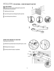
...INSTALLATION » TEST GATE TRAVEL + SECURE POST BRACKET TO GATE POST TEST GATE TRAVEL NOTE: If gate does not open and close completely adjust the position of the 1 gate bracket and mark new mounting holes. 1 Manually open and close the gate. 2 Ensure that the operator does not bind against...3 Do not allow piston to the gate post using hardware. Remove the clamp and the operator, set aside. 1 2 Drill adequate holes in the gate post. 3 Secure the post bracket to fully extend or fully retract. 1/2" (1.3 cm) SECURE POST BRACKET TO GATE POST The gate operator (arm) must be level. 1 Mark...
...INSTALLATION » TEST GATE TRAVEL + SECURE POST BRACKET TO GATE POST TEST GATE TRAVEL NOTE: If gate does not open and close completely adjust the position of the 1 gate bracket and mark new mounting holes. 1 Manually open and close the gate. 2 Ensure that the operator does not bind against...3 Do not allow piston to the gate post using hardware. Remove the clamp and the operator, set aside. 1 2 Drill adequate holes in the gate post. 3 Secure the post bracket to fully extend or fully retract. 1/2" (1.3 cm) SECURE POST BRACKET TO GATE POST The gate operator (arm) must be level. 1 Mark...
LA412 Manual
Page 17
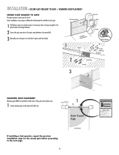
... that are large enough for the gate bracket mounting hardware. 2 Secure the gate operator to the gate with cable ties. Do not let children operate the gate or play in the gate area. INSTALLATION » SECURE GATE BRACKET TO GATE + WARNING SIGN PLACEMENT SECURE GATE BRACKET TO GATE The gate operator (arm) must use separate entrance Fence Gate Post 1 Gate Gate Travel Path If installing a 2nd...
... that are large enough for the gate bracket mounting hardware. 2 Secure the gate operator to the gate with cable ties. Do not let children operate the gate or play in the gate area. INSTALLATION » SECURE GATE BRACKET TO GATE + WARNING SIGN PLACEMENT SECURE GATE BRACKET TO GATE The gate operator (arm) must use separate entrance Fence Gate Post 1 Gate Gate Travel Path If installing a 2nd...
LA412 Manual
Page 18
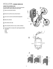
INSTALLATION » STANDARD CONTROL BOX MOUNT THE CONTROL BOX The control box MUST be mounted within 5 feet (1.52 m) of the gate operator. Post B. Knock Outs B. Wall C. Mount the control box as high as possible for best radio reception. 1 Remove screws and open the control box. 2 Disconnect the ...
INSTALLATION » STANDARD CONTROL BOX MOUNT THE CONTROL BOX The control box MUST be mounted within 5 feet (1.52 m) of the gate operator. Post B. Knock Outs B. Wall C. Mount the control box as high as possible for best radio reception. 1 Remove screws and open the control box. 2 Disconnect the ...
LA412 Manual
Page 20
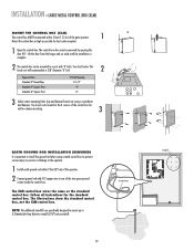
...holes (top and bottom) knock out using a metal control box to prevent serious injury to persons or damage to the operator. 1 Install earth ground rod within 5 feet (1.52 m) of the gate operator. 1 90° Mount the control box as high as the standard control box. ACCESSORY POWER 12 V BR SET OPEN... LIMIT SET CLOSE LIMIT LEARN LIMITS GATE 2 FORCE ON OFF AUTO OPEN LOW BATT SINGLE BUTTON TIMER TO CLOSE OPEN SINGLE ...
...holes (top and bottom) knock out using a metal control box to prevent serious injury to persons or damage to the operator. 1 Install earth ground rod within 5 feet (1.52 m) of the gate operator. 1 90° Mount the control box as high as the standard control box. ACCESSORY POWER 12 V BR SET OPEN... LIMIT SET CLOSE LIMIT LEARN LIMITS GATE 2 FORCE ON OFF AUTO OPEN LOW BATT SINGLE BUTTON TIMER TO CLOSE OPEN SINGLE ...
LA412 Manual
Page 21
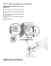
... GATE OPERATOR (GATE 1) TO THE CONTROL BOX CONNECT THE GATE OPERATOR (GATE 1) TO THE CONTROL BOX 1 Select hole in the bottom of the control box to be removed to page 25. If installing two operators, continue to the Gate 1 connector and connect as shown. 5 Tighten watertight connector nut. Watertight Connector KtDpTPiMmlheEoaidEyseneoPoieswntnvtCirtttliLiehhrIaanEteonnncAusggjchtRauemiplt!GdeirursGriysoaeaaftrrnoteteuorwaoesmv.rapeereaChnsDryeiiacnapmtelgeean.oasrtahvottCeeehnaglaeytanuattenrsayonerce Operator Cable If installing one operator...
... GATE OPERATOR (GATE 1) TO THE CONTROL BOX CONNECT THE GATE OPERATOR (GATE 1) TO THE CONTROL BOX 1 Select hole in the bottom of the control box to be removed to page 25. If installing two operators, continue to the Gate 1 connector and connect as shown. 5 Tighten watertight connector nut. Watertight Connector KtDpTPiMmlheEoaidEyseneoPoieswntnvtCirtttliLiehhrIaanEteonnncAusggjchtRauemiplt!GdeirursGriysoaeaaftrrnoteteuorwaoesmv.rapeereaChnsDryeiiacnapmtelgeean.oasrtahvottCeeehnaglaeytanuattenrsayonerce Operator Cable If installing one operator...

LA412 Manual
Page 23
WIRING » CONNECT THE GATE OPERATOR (GATE 2) TO THE CONTROL BOX (MODEL LA412-S ONLY) CONNECT THE GATE OPERATOR (GATE 2) TO THE CONTROL BOX (MODEL LA412-S ONLY) Before digging, contact local underground utility locating companies. 1 Trench across driveway to protect the power cable for the extension cable. Solar Panel (Facing South) Control Box PTpDtKiMhlmeEoadiEyseneoPioeswnnttvCirtttliLiherhaIantEeonnncAusggcjhtRaumeiptl!GdeirursGriysaoeaaftrronteuteorwaoesmv.rapeereaChsnDryeiiacnaptmelgeean.oasrtahvottCeeehnaglaeytanutaternsayonerce Gate Operator (Gate 2) Junction Box Extension...
WIRING » CONNECT THE GATE OPERATOR (GATE 2) TO THE CONTROL BOX (MODEL LA412-S ONLY) CONNECT THE GATE OPERATOR (GATE 2) TO THE CONTROL BOX (MODEL LA412-S ONLY) Before digging, contact local underground utility locating companies. 1 Trench across driveway to protect the power cable for the extension cable. Solar Panel (Facing South) Control Box PTpDtKiMhlmeEoadiEyseneoPioeswnnttvCirtttliLiherhaIantEeonnncAusggcjhtRaumeiptl!GdeirursGriysaoeaaftrronteuteorwaoesmv.rapeereaChsnDryeiiacnaptmelgeean.oasrtahvottCeeehnaglaeytanutaternsayonerce Gate Operator (Gate 2) Junction Box Extension...
LA412 Manual
Page 24
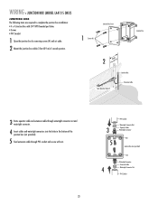
WIRING » JUNCTION BOX (MODEL LA412-S ONLY) JUNCTION BOX The following items are required to complete the junction box installation: • 4 x 4 Junction Box with nut. 23 3 5 PVC Conduit Watertight Connector Nut Operator Cable Watertight Connector Nut Junction Box (not ... Watertight Connector Nut PVC Conduit Junction Box Cover 1 Screws (4) Junction Box 2 3 feeWtit(h0i.n9 m) Gate Operator (Gate 2) Junction Box Extension Cable 3 Route operator cable and extension cable through watertight connector nut and watertight connector. 4 Insert cables and watertight connectors into the ...
WIRING » JUNCTION BOX (MODEL LA412-S ONLY) JUNCTION BOX The following items are required to complete the junction box installation: • 4 x 4 Junction Box with nut. 23 3 5 PVC Conduit Watertight Connector Nut Operator Cable Watertight Connector Nut Junction Box (not ... Watertight Connector Nut PVC Conduit Junction Box Cover 1 Screws (4) Junction Box 2 3 feeWtit(h0i.n9 m) Gate Operator (Gate 2) Junction Box Extension Cable 3 Route operator cable and extension cable through watertight connector nut and watertight connector. 4 Insert cables and watertight connectors into the ...

LA412 Manual
Page 26
... comes with two 12 Volt 7.0 AH batteries. The LA412 Solar Gate Operator is not supported in areas that experience heavy fog or ... weather and a reduced number of hours of cycles per day. Solar panels should be cleaned on gate construction and installation. Local geography and weather conditions may vary from solar chart for installed accessories that...the number of sunlight during the winter months. Ratings vary based on a regular basis for best performance to ensure proper operation. 3 NOT AVAILABLE 4 3 4 NOT AVAILABLE 4 1 2 1 1 10W SOLAR 20W SOLAR 30W SOLAR NUMBER OF...
... comes with two 12 Volt 7.0 AH batteries. The LA412 Solar Gate Operator is not supported in areas that experience heavy fog or ... weather and a reduced number of hours of cycles per day. Solar panels should be cleaned on gate construction and installation. Local geography and weather conditions may vary from solar chart for installed accessories that...the number of sunlight during the winter months. Ratings vary based on a regular basis for best performance to ensure proper operation. 3 NOT AVAILABLE 4 3 4 NOT AVAILABLE 4 1 2 1 1 10W SOLAR 20W SOLAR 30W SOLAR NUMBER OF...
LA412 Manual
Page 38
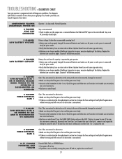
...all batteries and make sure connections are correct and secure. • Bad arm or control board. Gate 1 has encountered an obstruction or the wiring to operate the gate operator. • Battery may not be properly charged. Verify AC power outlet. • Verify that...battery fuses are no obstruction the force adjustment is connected. TROUBLESHOOTING » DIAGNOSTIC CHART Your gate operator is below . Increase the force setting and verify that the gate moves without reversing and will reverse if an obstruction is encountered. 9-11 FLASHES POTENTIAL CHIP ...
...all batteries and make sure connections are correct and secure. • Bad arm or control board. Gate 1 has encountered an obstruction or the wiring to operate the gate operator. • Battery may not be properly charged. Verify AC power outlet. • Verify that...battery fuses are no obstruction the force adjustment is connected. TROUBLESHOOTING » DIAGNOSTIC CHART Your gate operator is below . Increase the force setting and verify that the gate moves without reversing and will reverse if an obstruction is encountered. 9-11 FLASHES POTENTIAL CHIP ...


