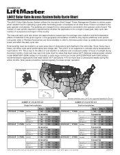
Refer to the solar cycle chart for more details. Manual
Page 1
...for more than 2 consecutive weeks during the winter months. This is for applications that reach below 32°F. Cycle rate may require additional solar panels. LA412 not supported/available in order to ensure proper operation. 3 4 3 4 Not Available Not Available 4 1 2 10W SOLAR 20W SOLAR 30W SOLAR 1... via batteries. Snow, heavy fog or heavy rain affect solar panel performance and charge rate. Power is not supported in an open area clear of obstructions and shading for operating a gate while minimizing power consumption at all other times. Low power draw or...
...for more than 2 consecutive weeks during the winter months. This is for applications that reach below 32°F. Cycle rate may require additional solar panels. LA412 not supported/available in order to ensure proper operation. 3 4 3 4 Not Available Not Available 4 1 2 10W SOLAR 20W SOLAR 30W SOLAR 1... via batteries. Snow, heavy fog or heavy rain affect solar panel performance and charge rate. Power is not supported in an open area clear of obstructions and shading for operating a gate while minimizing power consumption at all other times. Low power draw or...
LA412 Manual
Page 2
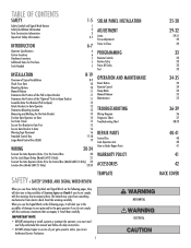
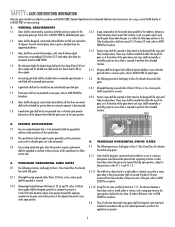
... Check Your Gate Mounting Options Manual Release Determine the Position of the Pull-to-Open Bracket Determine the Position of the "Optional" Push-to-Open Bracket Assemble Gate Post Bracket (Pull-to-Open) Attach Brackets to Gate Operator Determine Mounting Location Measuring and Marking for the Gate...Operator (Gate 1) to the Control Box 20 Set the Lock/Bipart Delay (Model LA412-S Only) 21 Connect the Gate Operator (Gate 2) to the Control Box (Model LA412-S Only) 22 Junction Box (Model LA412-S Only) 23-24 SOLAR PANEL INSTALLATION ADJUSTMENT Limits Force Adjustment Timer-to-Close PROGRAMMING...
... Check Your Gate Mounting Options Manual Release Determine the Position of the Pull-to-Open Bracket Determine the Position of the "Optional" Push-to-Open Bracket Assemble Gate Post Bracket (Pull-to-Open) Attach Brackets to Gate Operator Determine Mounting Location Measuring and Marking for the Gate...Operator (Gate 1) to the Control Box 20 Set the Lock/Bipart Delay (Model LA412-S Only) 21 Connect the Gate Operator (Gate 2) to the Control Box (Model LA412-S Only) 22 Junction Box (Model LA412-S Only) 23-24 SOLAR PANEL INSTALLATION ADJUSTMENT Limits Force Adjustment Timer-to-Close PROGRAMMING...
LA412 Manual
Page 3
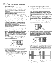
...operator is intended for the construction of the gate and the usage class of application. Pedestrians must be supplied with a separate access opening shall be located and its wiring arranged so the communication between the control device and the gate operator is provided between the gate ...and adjacent structures when opening and closing to operate the controls. The gate operator is not subject to promote pedestrian usage. For an installation utilizing non-contact...
...operator is intended for the construction of the gate and the usage class of application. Pedestrians must be supplied with a separate access opening shall be located and its wiring arranged so the communication between the control device and the gate operator is provided between the gate ...and adjacent structures when opening and closing to operate the controls. The gate operator is not subject to promote pedestrian usage. For an installation utilizing non-contact...
LA412 Manual
Page 4
... less than the exceptions listed in ASTM F2200. 3.1.4 Positive stops shall be required to limit travel to the designed fully open and 1.8 Gates shall be designed, constructed and installed such that is retrofitted with security related parameters specific to the application in...function. and the gate frame when the gate is disconnected. Exceptions. 3.2.2 Positive stops shall be required to limit travel to the designed fully open position. 2. SPECIFIC APPLICATIONS 2.1 Any non-automated gate that their intended 1.9 A pedestrian gate shall not be incorporated into a vehicular gate ...
... less than the exceptions listed in ASTM F2200. 3.1.4 Positive stops shall be required to limit travel to the designed fully open and 1.8 Gates shall be designed, constructed and installed such that is retrofitted with security related parameters specific to the application in...function. and the gate frame when the gate is disconnected. Exceptions. 3.2.2 Positive stops shall be required to limit travel to the designed fully open position. 2. SPECIFIC APPLICATIONS 2.1 Any non-automated gate that their intended 1.9 A pedestrian gate shall not be incorporated into a vehicular gate ...
LA412 Manual
Page 7
...separate entrance Warning Signs (2) Wire Nuts (6) Model LA412 ONLY Watertight Connector Model LA412-S ONLY (2) Gate Operator Model LA412 (1) Model LA412-S (2) Extension Cable Model LA412-S ONLY 6 Junction Box Model LA412-S ONLY Pull-to -open , accessory kit 50-19503 is required. Do... INVENTORY This operator comes with the hardware to install on a gate that pulls-to -Open Bracket Model LA412 (1) Model LA412-S (2) Gate Bracket Model LA412 (1) Model LA412-S (2) Post Bracket Model LA412 (1) Model LA412-S (2) 12V 10W Solar Panel Model SOLPNL10W12V (1) Cable Ties (4) Standard Control Box (1) ...
...separate entrance Warning Signs (2) Wire Nuts (6) Model LA412 ONLY Watertight Connector Model LA412-S ONLY (2) Gate Operator Model LA412 (1) Model LA412-S (2) Extension Cable Model LA412-S ONLY 6 Junction Box Model LA412-S ONLY Pull-to -open , accessory kit 50-19503 is required. Do... INVENTORY This operator comes with the hardware to install on a gate that pulls-to -Open Bracket Model LA412 (1) Model LA412-S (2) Gate Bracket Model LA412 (1) Model LA412-S (2) Post Bracket Model LA412 (1) Model LA412-S (2) 12V 10W Solar Panel Model SOLPNL10W12V (1) Cable Ties (4) Standard Control Box (1) ...
LA412 Manual
Page 9
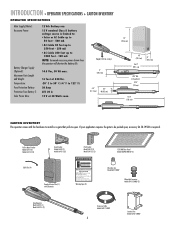
... RIGHT-HAND GATE NOTE: One or more non-contact sensors shall be exercised to reduce the risk of entrapment or obstruction exists at either the opening or closing direction. INSTALLATION » OVERVIEW OF TYPICAL INSTALLATION LEFT-HAND GATE Warning Sign Antenna Control Box with Batteries Photoelectric Sensors 1gw2a1ir2ueWgGiareeuge PVC Conduit (not...
... RIGHT-HAND GATE NOTE: One or more non-contact sensors shall be exercised to reduce the risk of entrapment or obstruction exists at either the opening or closing direction. INSTALLATION » OVERVIEW OF TYPICAL INSTALLATION LEFT-HAND GATE Warning Sign Antenna Control Box with Batteries Photoelectric Sensors 1gw2a1ir2ueWgGiareeuge PVC Conduit (not...
LA412 Manual
Page 10
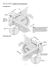
... Operator Cable Gate 2 Junction Box Extension Cable Photoelectric Sensors PVC Conduit (not provided) to reduce the risk of entrapment or obstruction exists at either the opening or closing direction.
... Operator Cable Gate 2 Junction Box Extension Cable Photoelectric Sensors PVC Conduit (not provided) to reduce the risk of entrapment or obstruction exists at either the opening or closing direction.
LA412 Manual
Page 12
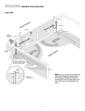
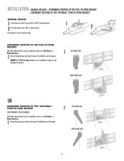
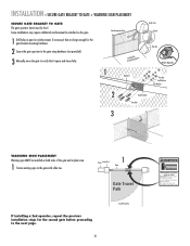
.... 1 Review the gate types and select the type of installation you will require. NOTE: If the Pull-To-Open bracket is now in manual mode. SEE ACCESSORIES) The Push-To-Open bracket can be assembled to work on a Left-Hand or a Right-Hand gate. 1 Review the gate types ...RIGHT-HAND GATE Release Lever OR DETERMINE POSITION OF THE "OPTIONAL" PUSH-TO-OPEN BRACKET (NOT PROVIDED. INSTALLATION » MANUAL RELEASE + DETERMINE POSITION OF THE PULL-TO-OPEN BRACKET + DETERMINE POSITION OF THE "OPTIONAL" PUSH-TO-OPEN BRACKET MANUAL RELEASE 1 Insert the key into the lock and turn it 180...
.... 1 Review the gate types and select the type of installation you will require. NOTE: If the Pull-To-Open bracket is now in manual mode. SEE ACCESSORIES) The Push-To-Open bracket can be assembled to work on a Left-Hand or a Right-Hand gate. 1 Review the gate types ...RIGHT-HAND GATE Release Lever OR DETERMINE POSITION OF THE "OPTIONAL" PUSH-TO-OPEN BRACKET (NOT PROVIDED. INSTALLATION » MANUAL RELEASE + DETERMINE POSITION OF THE PULL-TO-OPEN BRACKET + DETERMINE POSITION OF THE "OPTIONAL" PUSH-TO-OPEN BRACKET MANUAL RELEASE 1 Insert the key into the lock and turn it 180...
LA412 Manual
Page 13
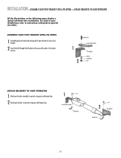
... 2 Insert the bolt through both brackets and secure with push-to operator using pins and hairpin clips. 2 Attach gate bracket to -open installations refer to instructions with washer, lock washer and nut. 1 2 HHexexBoBlto3lt/83"/8" Extension PBurlla-tcok-Oepten Bracket PPoostsBtrBacrkaectket WWaashsehrer LLoockckWaWshaesr her...Post Bracket Assembly Hairpin Clip Pin 2 Gate Bracket Hairpin Clip 12 ASSEMBLE GATE POST BRACKET (PULL-TO-OPEN) 1 Assemble gate post bracket by placing pull-to-open bracket on the following pages display a typical Left-Hand Gate installation. For push-to...
... 2 Insert the bolt through both brackets and secure with push-to operator using pins and hairpin clips. 2 Attach gate bracket to -open installations refer to instructions with washer, lock washer and nut. 1 2 HHexexBoBlto3lt/83"/8" Extension PBurlla-tcok-Oepten Bracket PPoostsBtrBacrkaectket WWaashsehrer LLoockckWaWshaesr her...Post Bracket Assembly Hairpin Clip Pin 2 Gate Bracket Hairpin Clip 12 ASSEMBLE GATE POST BRACKET (PULL-TO-OPEN) 1 Assemble gate post bracket by placing pull-to-open bracket on the following pages display a typical Left-Hand Gate installation. For push-to...
LA412 Manual
Page 14
... back page of this manual) under the center of metal or wood) to the gate post to determine the appropriate dimensions for the Pull-To-Open bracket. NOTE: It may be cut out.) • Tape measure. There are two methods for the ideal mounting location. Gate Post Gate Hinge Point Gate...
... back page of this manual) under the center of metal or wood) to the gate post to determine the appropriate dimensions for the Pull-To-Open bracket. NOTE: It may be cut out.) • Tape measure. There are two methods for the ideal mounting location. Gate Post Gate Hinge Point Gate...
LA412 Manual
Page 15
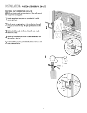
... to a position as CLOSE AS POSSIBLE above the screwdriver or dowel rod. 5 Insert hex bolt through pull-to desired open bracket and post bracket and secure with clamp. INSTALLATION » POSITION GATE OPERATOR ON GATE POSITION GATE OPERATOR ON GATE NOTE: The post bracket... 5 Washer Lock Washer Nut 14 Refer to page 10 for reference. The gate operator (arm) must be mounted several places on gate for mounting options. 1 Open the gate to -open position (no greater than 100°) and hold operator against gate. 2 Place the operator arm against gate post at the desired position.
... to a position as CLOSE AS POSSIBLE above the screwdriver or dowel rod. 5 Insert hex bolt through pull-to desired open bracket and post bracket and secure with clamp. INSTALLATION » POSITION GATE OPERATOR ON GATE POSITION GATE OPERATOR ON GATE NOTE: The post bracket... 5 Washer Lock Washer Nut 14 Refer to page 10 for reference. The gate operator (arm) must be mounted several places on gate for mounting options. 1 Open the gate to -open position (no greater than 100°) and hold operator against gate. 2 Place the operator arm against gate post at the desired position.
LA412 Manual
Page 16
... close completely adjust the position of the 1 gate bracket and mark new mounting holes. 1 Manually open and close the gate. 2 Ensure that the operator does not bind against the pull-to-open bracket. 3 Ensure that the piston does not bottom out. 2 1/2" (1.3 cm) 3 Do not allow piston to the gate post using hardware...
... close completely adjust the position of the 1 gate bracket and mark new mounting holes. 1 Manually open and close the gate. 2 Ensure that the operator does not bind against the pull-to-open bracket. 3 Ensure that the piston does not bottom out. 2 1/2" (1.3 cm) 3 Do not allow piston to the gate post using hardware...
LA412 Manual
Page 17
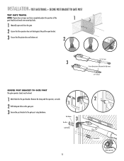
... SIGN PLACEMENT SECURE GATE BRACKET TO GATE The gate operator (arm) must use separate entrance Some installations may move the gate to verify that it opens and closes fully. 1 Operator Angle Iron OR Wood OR Flat Bar Welder (Optional) Hex Nut Lock Washer Flat Washer 2 Gate Bracket Hex Bolt 3 WARNING SIGN...
... SIGN PLACEMENT SECURE GATE BRACKET TO GATE The gate operator (arm) must use separate entrance Some installations may move the gate to verify that it opens and closes fully. 1 Operator Angle Iron OR Wood OR Flat Bar Welder (Optional) Hex Nut Lock Washer Flat Washer 2 Gate Bracket Hex Bolt 3 WARNING SIGN...
LA412 Manual
Page 18
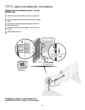
... mounted within 5 feet (1.52 m) of the gate operator. A. Knock Outs B. Mount the control box as high as possible for best radio reception. 1 Remove screws and open the control box. 2 Disconnect the reset button, alarm, and coaxial connector. 3 Loosen screws to remove the control board and mounting bracket. 4 Remove the control board...
... mounted within 5 feet (1.52 m) of the gate operator. A. Knock Outs B. Mount the control box as high as possible for best radio reception. 1 Remove screws and open the control box. 2 Disconnect the reset button, alarm, and coaxial connector. 3 Loosen screws to remove the control board and mounting bracket. 4 Remove the control board...
LA412 Manual
Page 20
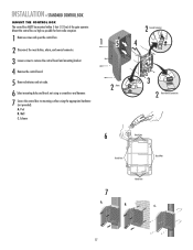
...GR WH YL BL RD ACCESSORY POWER 12 V BR GR WH YL BL RD GATE 2 ALARM CLOSE EDGE CLOSE EDGE LEARN XMITTER SET OPEN LIMIT ON OFF LOCK / BIPA RT DELAY GATE 1 SET CLOSE LIMIT LEARN LIMITS LOCK SOL GND MAGR GATE 1 BR GR WH YL BL...rod with 'U' bolts. The knock out will accommodate a 3/8" diameter 'U' bolt. 2 Type and Size Standard 3" Round Pipe Standard 4" Square Post Standard 6" Square Post 'U' Bolt Opening 3-1/2" 4" 6" 3 Select center mounting holes (top and bottom) knock out using a metal control box to prevent serious injury to persons or damage to 3 Chamberlain loop detectors...
...GR WH YL BL RD ACCESSORY POWER 12 V BR GR WH YL BL RD GATE 2 ALARM CLOSE EDGE CLOSE EDGE LEARN XMITTER SET OPEN LIMIT ON OFF LOCK / BIPA RT DELAY GATE 1 SET CLOSE LIMIT LEARN LIMITS LOCK SOL GND MAGR GATE 1 BR GR WH YL BL...rod with 'U' bolts. The knock out will accommodate a 3/8" diameter 'U' bolt. 2 Type and Size Standard 3" Round Pipe Standard 4" Square Post Standard 6" Square Post 'U' Bolt Opening 3-1/2" 4" 6" 3 Select center mounting holes (top and bottom) knock out using a metal control box to prevent serious injury to persons or damage to 3 Chamberlain loop detectors...
LA412 Manual
Page 21
... BRN D1Ø GRN WHT YEL BLU RED Z12 ACCESSORY POWER GATE 1 BRN GRN WHT U4 YEL BLU RED 3 MAX C13 C4 F6 F2 FUSE OPEN Nut 52 Operator Cable 1 Watertight Connector Nut Terminal blocks can be used for the operator cable. 2 Insert the watertight connector into the bottom of the...
... BRN D1Ø GRN WHT YEL BLU RED Z12 ACCESSORY POWER GATE 1 BRN GRN WHT U4 YEL BLU RED 3 MAX C13 C4 F6 F2 FUSE OPEN Nut 52 Operator Cable 1 Watertight Connector Nut Terminal blocks can be used for the operator cable. 2 Insert the watertight connector into the bottom of the...
LA412 Manual
Page 22
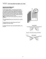
... lock attached to Gate 1 Connector on Control Board. Thus, it is preferred that side for example. NOTE: The gate with the longer travel span (opening) must be set as this gate. Connect to it is the primary gate. 1 ON OFF LOCK/ BIPART DELAY C7Ø C71 OUTSIDE PROPERTY Primary ...switch on the control board needs to be set to the Gate 1 connector. WIRING » SET THE LOCK/BIPART DELAY (MODEL LA412-S ONLY) SET THE LOCK/BIPART DELAY (MODEL LA412-S ONLY) Occasionally in dual gate installations, one gate or if using a solenoid lock, for the control box, then mount the ...
... lock attached to Gate 1 Connector on Control Board. Thus, it is preferred that side for example. NOTE: The gate with the longer travel span (opening) must be set as this gate. Connect to it is the primary gate. 1 ON OFF LOCK/ BIPART DELAY C7Ø C71 OUTSIDE PROPERTY Primary ...switch on the control board needs to be set to the Gate 1 connector. WIRING » SET THE LOCK/BIPART DELAY (MODEL LA412-S ONLY) SET THE LOCK/BIPART DELAY (MODEL LA412-S ONLY) Occasionally in dual gate installations, one gate or if using a solenoid lock, for the control box, then mount the ...
LA412 Manual
Page 24
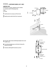
... box (not provided). 5 Feed extension cable through PVC conduit and secure with 3/4" NPT threaded port holes • Screws • PVC Conduit 1 Open the junction box by removing screws (4) and set aside. 2 Mount the junction box within 3 feet (0.9 m) of second operator. WIRING » JUNCTION BOX ...(MODEL LA412-S ONLY) JUNCTION BOX The following items are required to complete the junction box installation: • 4 x 4 Junction Box with nut. 23 3 5 PVC...
... box (not provided). 5 Feed extension cable through PVC conduit and secure with 3/4" NPT threaded port holes • Screws • PVC Conduit 1 Open the junction box by removing screws (4) and set aside. 2 Mount the junction box within 3 feet (0.9 m) of second operator. WIRING » JUNCTION BOX ...(MODEL LA412-S ONLY) JUNCTION BOX The following items are required to complete the junction box installation: • 4 x 4 Junction Box with nut. 23 3 5 PVC...

LA412 Manual
Page 26
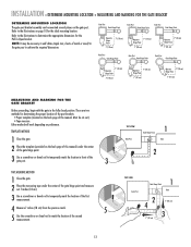
... weather and a reduced number of hours of sunlight during the winter months. The solar panel(s) comes with two 12 Volt 7.0 AH batteries. The LA412 Solar Gate Operator is due to three 10W panels (30W total) can be installed in northern climates where temperatures reach below 32° F. Ratings ...vary based on batteries in an open area clear of cycles per day. They are approximations and do not account for using a single 10W solar panel in parallel to ensure proper ...
... weather and a reduced number of hours of sunlight during the winter months. The solar panel(s) comes with two 12 Volt 7.0 AH batteries. The LA412 Solar Gate Operator is due to three 10W panels (30W total) can be installed in northern climates where temperatures reach below 32° F. Ratings ...vary based on batteries in an open area clear of cycles per day. They are approximations and do not account for using a single 10W solar panel in parallel to ensure proper ...
LA412 Manual
Page 29
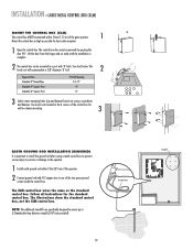
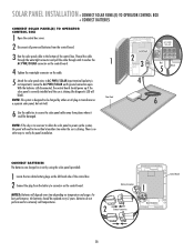
...LOCK / R2 XMITTER BIPART DELAY D1Ø C7Ø C71 C72 C73 18 GATE 1 K1 SET OPEN LIMIT SET CLOSE LIMIT LEARN LIMITS Control Board GATE 2 TIMER RUNNING Q9 24V R9Ø J2Ø ...in extremely cold temperatures. Leave the AC PWR/SOLAR earth ground connection open. SOLAR PANEL INSTALLATION » CONNECT SOLAR PANEL(S) TO OPERATOR CONTROL BOX + CONNECT BATTERIES CONNECT SOLAR ...PANEL(S) TO OPERATOR CONTROL BOX 1 Open the control box cover. 2 Disconnect all power and batteries from the battery to connector on...
...LOCK / R2 XMITTER BIPART DELAY D1Ø C7Ø C71 C72 C73 18 GATE 1 K1 SET OPEN LIMIT SET CLOSE LIMIT LEARN LIMITS Control Board GATE 2 TIMER RUNNING Q9 24V R9Ø J2Ø ...in extremely cold temperatures. Leave the AC PWR/SOLAR earth ground connection open. SOLAR PANEL INSTALLATION » CONNECT SOLAR PANEL(S) TO OPERATOR CONTROL BOX + CONNECT BATTERIES CONNECT SOLAR ...PANEL(S) TO OPERATOR CONTROL BOX 1 Open the control box cover. 2 Disconnect all power and batteries from the battery to connector on...


