

LA400 Manual
Page 2
... Box Large Metal Control Box (XLM) WIRING Connect the Gate Operator (Gate 1) to the Control Box Set the Bipart Delay (Model LA400-S Only) Connect the Gate Operator (Gate 2) to the Control Box (Model LA400-S Only) Junction Box (Model LA400-S Only) Connect Transformer to Control Board Earth Ground Rod Installation ...187; SAFETY SYMBOL AND SIGNAL WORD REVIEW When you see this manual and follow all safety instructions. • DO NOT attempt repair or service of your gate and/or the gate operator if you do not comply with the cautionary statements that accompany them carefully. Read them ....
... Box Large Metal Control Box (XLM) WIRING Connect the Gate Operator (Gate 1) to the Control Box Set the Bipart Delay (Model LA400-S Only) Connect the Gate Operator (Gate 2) to the Control Box (Model LA400-S Only) Junction Box (Model LA400-S Only) Connect Transformer to Control Board Earth Ground Rod Installation ...187; SAFETY SYMBOL AND SIGNAL WORD REVIEW When you see this manual and follow all safety instructions. • DO NOT attempt repair or service of your gate and/or the gate operator if you do not comply with the cautionary statements that accompany them carefully. Read them ....

LA400 Manual
Page 4
...gate system is specifically designed for Exposed Rollers • Photoelectric Sensors • Screen Mesh • Vertical Posts • Instructional and Precautionary Signage 4. A gate operator can create risks for the user as well as a component part of a swing gate. b. c. Locate the gate...from the bottom of the gate to a minimum of 4 feet (1.2 m) above the ground at the bottom edge of the gate operator. 8. For a gate operator utilizing a non-contact sensor: a. Reference owner's manual regarding placement of entrapment or obstruction exists, such as the one or more ...
...gate system is specifically designed for Exposed Rollers • Photoelectric Sensors • Screen Mesh • Vertical Posts • Instructional and Precautionary Signage 4. A gate operator can create risks for the user as well as a component part of a swing gate. b. c. Locate the gate...from the bottom of the gate to a minimum of 4 feet (1.2 m) above the ground at the bottom edge of the gate operator. 8. For a gate operator utilizing a non-contact sensor: a. Reference owner's manual regarding placement of entrapment or obstruction exists, such as the one or more ...

LA400 Manual
Page 6
... and RIGID objects, such as posts. • A swinging gate shall NOT open and close gate. • NEVER use only LiftMaster part #K74-30762 for disposal instructions. NOTE: The operator should be visible and clearly labeled. • ALL power and control wiring MUST be run the... operator without consulting the wiring diagram. Operator MUST be enclosed in fire. To AVOID damaging plug-in transformer, it MUST be properly grounded...
... and RIGID objects, such as posts. • A swinging gate shall NOT open and close gate. • NEVER use only LiftMaster part #K74-30762 for disposal instructions. NOTE: The operator should be visible and clearly labeled. • ALL power and control wiring MUST be run the... operator without consulting the wiring diagram. Operator MUST be enclosed in fire. To AVOID damaging plug-in transformer, it MUST be properly grounded...
LA400 Manual
Page 7
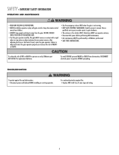
... sensors. Failure to persons use separate entrance. • Disconnect ALL power before performing ANY maintenance. • ALL maintenance MUST be performed by a LiftMaster professional. • SAVE THESE INSTRUCTIONS. To reduce the risk of FIRE or INJURY to adjust and retest the gate operator properly can increase the risk of travel, retest the gate...
... sensors. Failure to persons use separate entrance. • Disconnect ALL power before performing ANY maintenance. • ALL maintenance MUST be performed by a LiftMaster professional. • SAVE THESE INSTRUCTIONS. To reduce the risk of FIRE or INJURY to adjust and retest the gate operator properly can increase the risk of travel, retest the gate...
LA400 Manual
Page 9
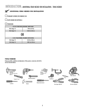
... TRANSFORMER (STRANDED COPPER WIRE) Wire Gauge 14 500 feet (152 m) Wire Gauge 12 1000 feet (305 m) TOOLS NEEDED During assembly, installation and adjustment of the operator, instructions will call for tools as illustrated below. Deep Well Sockets and Wrench 1/2", 5/8", 7/16", 9/16" and 1/4" Carpenter's Level Screwdriver Drill Adjustable End Wrench Drill Bits 1/2", 3/16...
... TRANSFORMER (STRANDED COPPER WIRE) Wire Gauge 14 500 feet (152 m) Wire Gauge 12 1000 feet (305 m) TOOLS NEEDED During assembly, installation and adjustment of the operator, instructions will call for tools as illustrated below. Deep Well Sockets and Wrench 1/2", 5/8", 7/16", 9/16" and 1/4" Carpenter's Level Screwdriver Drill Adjustable End Wrench Drill Bits 1/2", 3/16...
LA400 Manual
Page 14
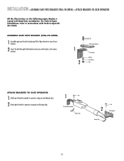
For Push-to-Open installations refer to instructions with washer, lock washer and nut. 1 2 HeexxBBolot l3t/38/"8" Extension PBurlla-tcok-Oepten Bracket PPoostsBtrBacrkaectket WWaashsehrer LLoockckWaWshaesr her NNuut t ATTACH BRACKETS TO GATE OPERATOR 1 Attach post bracket assembly to operator using pins and hairpin clips. 2 Attach gate bracket to ... the illustrations on top of post bracket. 2 Insert the bolt through both brackets and secure with Push-to operator using pins and hairpin clips. 1 Pin Post Bracket Assembly Hairpin Clip Pin 2 Gate Bracket Hairpin Clip 13 ASSEMBLE ...
For Push-to-Open installations refer to instructions with washer, lock washer and nut. 1 2 HeexxBBolot l3t/38/"8" Extension PBurlla-tcok-Oepten Bracket PPoostsBtrBacrkaectket WWaashsehrer LLoockckWaWshaesr her NNuut t ATTACH BRACKETS TO GATE OPERATOR 1 Attach post bracket assembly to operator using pins and hairpin clips. 2 Attach gate bracket to ... the illustrations on top of post bracket. 2 Insert the bolt through both brackets and secure with Push-to operator using pins and hairpin clips. 1 Pin Post Bracket Assembly Hairpin Clip Pin 2 Gate Bracket Hairpin Clip 13 ASSEMBLE ...

LA400 Manual
Page 22
... 1 2 120 Vac ONLY The XLM control box wires the same as the standard control box. Follow all instructions for the control board power supply. The second receptacle can be removed to power up additional gate operator accessories. The illustrations show the standard control box, not the XLM control box. 21 One of...
... 1 2 120 Vac ONLY The XLM control box wires the same as the standard control box. Follow all instructions for the control board power supply. The second receptacle can be removed to power up additional gate operator accessories. The illustrations show the standard control box, not the XLM control box. 21 One of...
LA400 Manual
Page 41
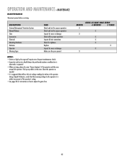
... and test for proper operation Check and test for proper operation Inspect for wear or damage Check all for proper operation Inspect all wire connections Check for tightness Replace Inspect for instructions on how to the operator it is within ten percent of the operator and the area around the operator. Clean the operator as needed. • It...
... and test for proper operation Check and test for proper operation Inspect for wear or damage Check all for proper operation Inspect all wire connections Check for tightness Replace Inspect for instructions on how to the operator it is within ten percent of the operator and the area around the operator. Clean the operator as needed. • It...

LA400 Manual
Page 44
...GATE OPENS BUT DOES NOT CLOSE Audible beeps (3 times) when command is given, but the operator does not move. Voltage must be connected. See Programming Remote instructions. Connect batteries. Replace motor. See Installation section of wires. Use reference chart on next ...page to -Close section for adjustment instructions. See Programming Limits section for circuit board. Check for obstruction on Obstruction Reversal. 3) Operator in "Party Mode". 4) Constant Open Command (Check LED's). TROUBLESHOOTING » TROUBLESHOOTING CHART FAULT OPERATOR IS DEAD No LED lights are on...
...GATE OPENS BUT DOES NOT CLOSE Audible beeps (3 times) when command is given, but the operator does not move. Voltage must be connected. See Programming Remote instructions. Connect batteries. Replace motor. See Installation section of wires. Use reference chart on next ...page to -Close section for adjustment instructions. See Programming Limits section for circuit board. Check for obstruction on Obstruction Reversal. 3) Operator in "Party Mode". 4) Constant Open Command (Check LED's). TROUBLESHOOTING » TROUBLESHOOTING CHART FAULT OPERATOR IS DEAD No LED lights are on...
LA400 Manual
Page 46
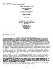
...legal rights, and you may not apply to state. 45 warrants to the first purchaser of -purchase receipt with the instructions regarding installation, operation, maintenance and testing. You will be advised of purchase. Defective parts will be repaired or replaced with those... or exclusion may not apply to Seller for warranty repair. Technical Support Group 6050 S. Country Club Road Tucson, AZ 85706 WARRANTY POLICY LIFTMASTER TWO YEAR LIMITED WARRANTY The Chamberlain Group, Inc. Failure to contain a defect covered by this limited warranty, will void this limited warranty...
...legal rights, and you may not apply to state. 45 warrants to the first purchaser of -purchase receipt with the instructions regarding installation, operation, maintenance and testing. You will be advised of purchase. Defective parts will be repaired or replaced with those... or exclusion may not apply to Seller for warranty repair. Technical Support Group 6050 S. Country Club Road Tucson, AZ 85706 WARRANTY POLICY LIFTMASTER TWO YEAR LIMITED WARRANTY The Chamberlain Group, Inc. Failure to contain a defect covered by this limited warranty, will void this limited warranty...


