
LA400 Manual
Page 1
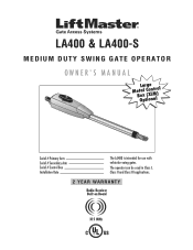
LA400 & LA400-S MEDIUM DUTY SWING GATE OPERATOR OWNER'S MANUAL MeBtOoLaaxplrtC(giXooennLMatrl)ol Serial # Primary Arm Serial # Secondary Arm Serial # Control Box Installation Date The LA400 is intended for use with vehicular swing gates. The operator can be used in Class I, Class II and Class III applications. 2 YEAR WARRANTY Radio Receiver Built on Board 315 MHz
LA400 & LA400-S MEDIUM DUTY SWING GATE OPERATOR OWNER'S MANUAL MeBtOoLaaxplrtC(giXooennLMatrl)ol Serial # Primary Arm Serial # Secondary Arm Serial # Control Box Installation Date The LA400 is intended for use with vehicular swing gates. The operator can be used in Class I, Class II and Class III applications. 2 YEAR WARRANTY Radio Receiver Built on Board 315 MHz

LA400 Manual
Page 2
...) WIRING Connect the Gate Operator (Gate 1) to the Control Box Set the Bipart Delay (Model LA400-S Only) Connect the Gate Operator (Gate 2) to the Control Box (Model LA400-S Only) Junction Box (Model LA400-S Only) Connect Transformer to Control Board Earth Ground Rod Installation (Optional) Connect Batteries 1-6 1 ...Inputs (P6-7-8 and 9) Safety Accessories for Secondary Entrapment Protection OPERATION AND MAINTENANCE Reset Button Remote Control Manual Release Maintenance TROUBLESHOOTING Basic Control Board Layout Wiring Diagram Diagnostic Codes Troubleshooting Chart REPAIR PARTS Control Box ...
...) WIRING Connect the Gate Operator (Gate 1) to the Control Box Set the Bipart Delay (Model LA400-S Only) Connect the Gate Operator (Gate 2) to the Control Box (Model LA400-S Only) Junction Box (Model LA400-S Only) Connect Transformer to Control Board Earth Ground Rod Installation (Optional) Connect Batteries 1-6 1 ...Inputs (P6-7-8 and 9) Safety Accessories for Secondary Entrapment Protection OPERATION AND MAINTENANCE Reset Button Remote Control Manual Release Maintenance TROUBLESHOOTING Basic Control Board Layout Wiring Diagram Diagnostic Codes Troubleshooting Chart REPAIR PARTS Control Box ...

LA400 Manual
Page 4
..., such as at any moving . Gate systems design and installation must be located where the risk of the gate where easily visible. 11. Reference owner's manual regarding placement of non-contact sensor for installation only on each type of the vehicular gate. 6. Specific safety features include: • Gate Edges • Guards...
..., such as at any moving . Gate systems design and installation must be located where the risk of the gate where easily visible. 11. Reference owner's manual regarding placement of non-contact sensor for installation only on each type of the vehicular gate. 6. Specific safety features include: • Gate Edges • Guards...

LA400 Manual
Page 5
... specification in the open position. 2. gate will enter a receiver guide, refer to ASTM F2200 for panel types. 1.5 An existing gate latch shall be disabled when a manually operated gate is to be automated shall be upgraded to conform to the provisions of the protrusions not exceeding 0.50 inches (12.7 mm) when other...
... specification in the open position. 2. gate will enter a receiver guide, refer to ASTM F2200 for panel types. 1.5 An existing gate latch shall be disabled when a manually operated gate is to be automated shall be upgraded to conform to the provisions of the protrusions not exceeding 0.50 inches (12.7 mm) when other...
LA400 Manual
Page 7
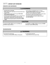
...continued protection against fire and electrocution: • Disconnect power and battery BEFORE installing or servicing operator. Pedestrians MUST use only LiftMaster part #K74-30762 for vehicles ONLY. NO ONE SHOULD CROSS THE PATH OF THE MOVING GATE. • Test the ...gate operator monthly. Read the ownerʼs manual. Failure to persons use separate entrance. • Disconnect ALL power before performing ANY maintenance. • ALL maintenance MUST be performed by a LiftMaster professional. • SAVE THESE INSTRUCTIONS. TROUBLESHOOTING To protect against fire...
...continued protection against fire and electrocution: • Disconnect power and battery BEFORE installing or servicing operator. Pedestrians MUST use only LiftMaster part #K74-30762 for vehicles ONLY. NO ONE SHOULD CROSS THE PATH OF THE MOVING GATE. • Test the ...gate operator monthly. Read the ownerʼs manual. Failure to persons use separate entrance. • Disconnect ALL power before performing ANY maintenance. • ALL maintenance MUST be performed by a LiftMaster professional. • SAVE THESE INSTRUCTIONS. TROUBLESHOOTING To protect against fire...
LA400 Manual
Page 13
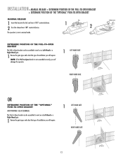
... the type of installation you will require. 1 LEFT-HAND GATE RIGHT-HAND GATE 12 INSTALLATION » MANUAL RELEASE + DETERMINE POSITION OF THE PULL-TO-OPEN BRACKET + DETERMINE POSITION OF THE "OPTIONAL" PUSH-TO-OPEN BRACKET MANUAL RELEASE 1 Insert the key into the lock and turn it 180° counterclockwise. 2 Turn the release... GATE Release Lever OR DETERMINE POSITION OF THE "OPTIONAL" PUSH-TO-OPEN BRACKET (NOT PROVIDED. NOTE: If the Pull-to-Open bracket is now in manual mode.
... the type of installation you will require. 1 LEFT-HAND GATE RIGHT-HAND GATE 12 INSTALLATION » MANUAL RELEASE + DETERMINE POSITION OF THE PULL-TO-OPEN BRACKET + DETERMINE POSITION OF THE "OPTIONAL" PUSH-TO-OPEN BRACKET MANUAL RELEASE 1 Insert the key into the lock and turn it 180° counterclockwise. 2 Turn the release... GATE Release Lever OR DETERMINE POSITION OF THE "OPTIONAL" PUSH-TO-OPEN BRACKET (NOT PROVIDED. NOTE: If the Pull-to-Open bracket is now in manual mode.
LA400 Manual
Page 15
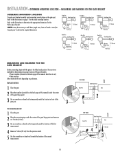
Must be necessary to the illustrations on the back page of this manual. Gate Post Gate Hinge Point Gate Post Gate Hinge Point Gate Post Gate Hinge Point Operator Hinge Point 7" (18 cm) 7" (18 cm) Operator 7" (18 cm) ... illustrations to determine the appropriate dimensions for determining the proper location of the post brackets: • Paper template (Located on the back page of this manual) under the center of the gate hinge point and measure out 7 inches (18 cm). 3 Use a screwdriver or dowel rod to temporarily mark the location of...
Must be necessary to the illustrations on the back page of this manual. Gate Post Gate Hinge Point Gate Post Gate Hinge Point Gate Post Gate Hinge Point Operator Hinge Point 7" (18 cm) 7" (18 cm) Operator 7" (18 cm) ... illustrations to determine the appropriate dimensions for determining the proper location of the post brackets: • Paper template (Located on the back page of this manual) under the center of the gate hinge point and measure out 7 inches (18 cm). 3 Use a screwdriver or dowel rod to temporarily mark the location of...
LA400 Manual
Page 17
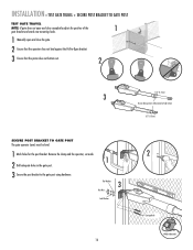
... POST TEST GATE TRAVEL NOTE: If gate does not open and close completely adjust the position of the 1 gate bracket and mark new mounting holes. 1 Manually open and close the gate. 2 Ensure that the operator does not bind against the Pull-to-Open bracket. 3 Ensure that the piston does not bottom...
... POST TEST GATE TRAVEL NOTE: If gate does not open and close completely adjust the position of the 1 gate bracket and mark new mounting holes. 1 Manually open and close the gate. 2 Ensure that the operator does not bind against the Pull-to-Open bracket. 3 Ensure that the piston does not bottom...
LA400 Manual
Page 18
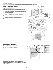
... installing a 2nd operator, repeat the previous installation steps for the gate bracket mounting hardware. 2 Secure the gate operator to the gate using hardware (not provided). 3 Manually move at any time without prior warning. INSTALLATION » SECURE GATE BRACKET TO GATE + WARNING SIGN PLACEMENT SECURE GATE BRACKET TO GATE The gate operator...
... installing a 2nd operator, repeat the previous installation steps for the gate bracket mounting hardware. 2 Secure the gate operator to the gate using hardware (not provided). 3 Manually move at any time without prior warning. INSTALLATION » SECURE GATE BRACKET TO GATE + WARNING SIGN PLACEMENT SECURE GATE BRACKET TO GATE The gate operator...
LA400 Manual
Page 40
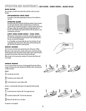
...cycle another activation of the remote control will stop , the alarm will sound (up to 5 minutes) and the control board will close the gate. MANUAL RELEASE In case of a power failure, the operator can be disengaged from the gate. With an operator, the release action may sometimes feel stiff/jerky... and store in the open position, activation of the remote control button will close the gate and return the operator to leave the gate(s) in manual mode and the gate can be opened and closed position, activation of the remote control button will open the gate. This engages the motor. 1 ...
...cycle another activation of the remote control will stop , the alarm will sound (up to 5 minutes) and the control board will close the gate. MANUAL RELEASE In case of a power failure, the operator can be disengaged from the gate. With an operator, the release action may sometimes feel stiff/jerky... and store in the open position, activation of the remote control button will close the gate and return the operator to leave the gate(s) in manual mode and the gate can be opened and closed position, activation of the remote control button will open the gate. This engages the motor. 1 ...
LA400 Manual
Page 41
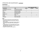
.... • It is suggested that the incoming voltage to adjust the gate force. Pick up any debris in the area. DESCRIPTION External Entrapment Protection System Manual Release Gate Accessories Electrical Mounting Hardware Batteries Operator Warning Signs TASK Check and test for proper operation Check and test for proper operation Inspect for...
.... • It is suggested that the incoming voltage to adjust the gate force. Pick up any debris in the area. DESCRIPTION External Entrapment Protection System Manual Release Gate Accessories Electrical Mounting Hardware Batteries Operator Warning Signs TASK Check and test for proper operation Check and test for proper operation Inspect for...

LA400 Pull to Open Addendum Manual
Page 1
Place opener against gate post and adjust the opener until the required dimension is being added to the LA400, offering greater mounting flexibility. Ideally, the distance between and opener hinge points should be used to mount operator if needed Addendum to 30-...degrees of movement in some applications. Typical 4" Post Hole NOTE: The addition of this hole helps add up to LA400 Owner's Manual Acceptable Configurations (will vary based on site conditions) DETERMINE MOUNTING LOCATION The gate post bracket assembly can be mounted several places on the gate ...
Place opener against gate post and adjust the opener until the required dimension is being added to the LA400, offering greater mounting flexibility. Ideally, the distance between and opener hinge points should be used to mount operator if needed Addendum to 30-...degrees of movement in some applications. Typical 4" Post Hole NOTE: The addition of this hole helps add up to LA400 Owner's Manual Acceptable Configurations (will vary based on site conditions) DETERMINE MOUNTING LOCATION The gate post bracket assembly can be mounted several places on the gate ...
LA400 Pull to Open Addendum Manual
Page 2
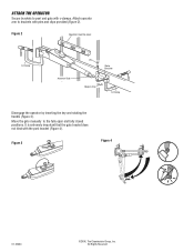
Move the gate manually to brackets with pins and clips provided (Figure 2). All Rights Reserved Figure 2 Operator must be level C-Clamp Actuator Side Pin Gate Bracket Hairpin Clip C-Clamp Disengage the operator by inserting the key and rotating the handle (Figure 3). It is extremely important that the gate bracket does not bind with c-clamps. Figure 3 Figure 4 01-33464 ©2006, The Chamberlain Group, Inc. ATTACH THE OPERATOR Secure brackets to post and gate with the post bracket (Figure 4). Attach operator arm to the fully open and fully closed positions.
Move the gate manually to brackets with pins and clips provided (Figure 2). All Rights Reserved Figure 2 Operator must be level C-Clamp Actuator Side Pin Gate Bracket Hairpin Clip C-Clamp Disengage the operator by inserting the key and rotating the handle (Figure 3). It is extremely important that the gate bracket does not bind with c-clamps. Figure 3 Figure 4 01-33464 ©2006, The Chamberlain Group, Inc. ATTACH THE OPERATOR Secure brackets to post and gate with the post bracket (Figure 4). Attach operator arm to the fully open and fully closed positions.


