

LA400 Manual
Page 8
... (1) • Hairpin Clip (2) • Pin (2) • Hex Bolt 3/8"-16 X 1-1/2" (1) • Bolt 2-3/4" (2) • Keylock Cap (1) • Keys (2) 7 IP56 (1) • Phillips Head Mounting Screws (4) • Anchors (4) • Terminal Block - Six Conductor, 9 feet (2.7 m) • Warning Sign (2) • Battery ...(2) • Plug-in Transformer (1) LA400-S (SECOND GATE OPERATOR ARM) • Motor Cable - Six Conductor, 40 feet (12.2 m) • Junction Box - INTRODUCTION » ...
... (1) • Hairpin Clip (2) • Pin (2) • Hex Bolt 3/8"-16 X 1-1/2" (1) • Bolt 2-3/4" (2) • Keylock Cap (1) • Keys (2) 7 IP56 (1) • Phillips Head Mounting Screws (4) • Anchors (4) • Terminal Block - Six Conductor, 9 feet (2.7 m) • Warning Sign (2) • Battery ...(2) • Plug-in Transformer (1) LA400-S (SECOND GATE OPERATOR ARM) • Motor Cable - Six Conductor, 40 feet (12.2 m) • Junction Box - INTRODUCTION » ...
LA400 Manual
Page 13
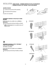
... PULL-TO-OPEN BRACKET + DETERMINE POSITION OF THE "OPTIONAL" PUSH-TO-OPEN BRACKET MANUAL RELEASE 1 Insert the key into the lock and turn it 180° counterclockwise. 2 Turn the release lever 180° counterclockwise. Key 1 2 DETERMINE POSITION OF THE PULL-TO-OPEN BRACKET The Pull-to-Open bracket can be assembled to...
... PULL-TO-OPEN BRACKET + DETERMINE POSITION OF THE "OPTIONAL" PUSH-TO-OPEN BRACKET MANUAL RELEASE 1 Insert the key into the lock and turn it 180° counterclockwise. 2 Turn the release lever 180° counterclockwise. Key 1 2 DETERMINE POSITION OF THE PULL-TO-OPEN BRACKET The Pull-to-Open bracket can be assembled to...
LA400 Manual
Page 31
... the LEARN LIMITS button. If the problem continues, see Troubleshooting section.) Test the limits by turning the release lever clockwise 180°, then turning the key clockwise 180°. If a mistake is in the desired position, press the LEARN LIMITS button again. DIAGNOSTIC GATE 1 SET CLOSE OR SINGLE ARM RIGHT-HAND...
... the LEARN LIMITS button. If the problem continues, see Troubleshooting section.) Test the limits by turning the release lever clockwise 180°, then turning the key clockwise 180°. If a mistake is in the desired position, press the LEARN LIMITS button again. DIAGNOSTIC GATE 1 SET CLOSE OR SINGLE ARM RIGHT-HAND...
LA400 Manual
Page 32
... close the left operator. If the problem continues, see Troubleshooting section.) Test the limits by turning the release lever clockwise 180°, then turning the key clockwise 180°. Programming times-out automatically after 60 seconds of inactivity. DIAGNOSTIC GATE 1 SET CLOSE 5 Press the GATE 2 right button to open the left...
... close the left operator. If the problem continues, see Troubleshooting section.) Test the limits by turning the release lever clockwise 180°, then turning the key clockwise 180°. Programming times-out automatically after 60 seconds of inactivity. DIAGNOSTIC GATE 1 SET CLOSE 5 Press the GATE 2 right button to open the left...

LA400 Manual
Page 33
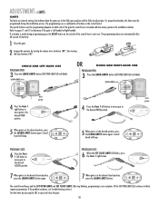
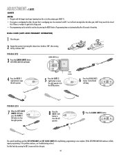
...; The gate with the longer travel span (opening) must be exited at any time by turning the release lever clockwise 180°, then turning the key clockwise 180°. DUAL GATE (RIGHT-SIDE PRIMARY OPERATOR) 1 Close the gate. 2 Engage the operator by pressing the RESET button. PROGRAM CLOSE 7 When the SET...
...; The gate with the longer travel span (opening) must be exited at any time by turning the release lever clockwise 180°, then turning the key clockwise 180°. DUAL GATE (RIGHT-SIDE PRIMARY OPERATOR) 1 Close the gate. 2 Engage the operator by pressing the RESET button. PROGRAM CLOSE 7 When the SET...
LA400 Manual
Page 40
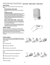
...(s) in the open cycle another activation of the remote control will stop , the alarm will require resetting. RELEASE 1 Insert the key into the lock. 2 Turn the key counter-clockwise 180°. 3 Turn the release lever counter-clockwise 180°. After the operator is reset, normal functions will close... When the gate is in the closed manually. This engages the motor. 1 2 Turn the key clockwise 180°. Operator is in a safe place. This locks the release lever. 3 Remove the key and store in manual mode and the gate can be opened and closed position, activation of the...
...(s) in the open cycle another activation of the remote control will stop , the alarm will require resetting. RELEASE 1 Insert the key into the lock. 2 Turn the key counter-clockwise 180°. 3 Turn the release lever counter-clockwise 180°. After the operator is reset, normal functions will close... When the gate is in the closed manually. This engages the motor. 1 2 Turn the key clockwise 180°. Operator is in a safe place. This locks the release lever. 3 Remove the key and store in manual mode and the gate can be opened and closed position, activation of the...

LA400 Manual
Page 45
... Release Lever 1 2 41ASWG-438SA Motor with Limit 1 11 Switch Harness 3 41ASWG-0014SA Rear Connector 1 4 41ASWG-489 Cable 24 V with Connector 1 Not Shown 41ASWG-0119 Release Key 1 K77-19130 Hardware Bag Complete with: Gate bracket, post bracket, Pull-to-Open bracket and hardware 44 44
... Release Lever 1 2 41ASWG-438SA Motor with Limit 1 11 Switch Harness 3 41ASWG-0014SA Rear Connector 1 4 41ASWG-489 Cable 24 V with Connector 1 Not Shown 41ASWG-0119 Release Key 1 K77-19130 Hardware Bag Complete with: Gate bracket, post bracket, Pull-to-Open bracket and hardware 44 44
LA400 Manual
Page 47
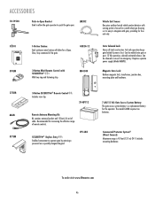
...OPEN 370LM 1-Button Station: Steel enclosure wired station will allow the gate operator to push the gate open. To order visit www.liftmaster.com 46 Gate Solenoid Lock: Heavy all steel construction. Can be welded onto gate or post. 12 Vdc operation, solenoid-activated release.... The model LA400 requires two batteries. CPS-LN4 7 AH/12 Vdc Gate Access System Battery: The gate access system battery is easy to integrate with SECURITY✚® : With key ring and fastening strip. Commercial Protector System® (Direct Connect...
...OPEN 370LM 1-Button Station: Steel enclosure wired station will allow the gate operator to push the gate open. To order visit www.liftmaster.com 46 Gate Solenoid Lock: Heavy all steel construction. Can be welded onto gate or post. 12 Vdc operation, solenoid-activated release.... The model LA400 requires two batteries. CPS-LN4 7 AH/12 Vdc Gate Access System Battery: The gate access system battery is easy to integrate with SECURITY✚® : With key ring and fastening strip. Commercial Protector System® (Direct Connect...
LA400 Pull to Open Addendum Manual
Page 2
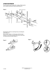
Figure 3 Figure 4 01-33464 ©2006, The Chamberlain Group, Inc. Move the gate manually to brackets with pins and clips provided (Figure 2). It is extremely important that the gate bracket does not bind with c-clamps. Attach operator arm to the fully open and fully closed positions. All Rights Reserved Figure 2 Operator must be level C-Clamp Actuator Side Pin Gate Bracket Hairpin Clip C-Clamp Disengage the operator by inserting the key and rotating the handle (Figure 3). ATTACH THE OPERATOR Secure brackets to post and gate with the post bracket (Figure 4).
Figure 3 Figure 4 01-33464 ©2006, The Chamberlain Group, Inc. Move the gate manually to brackets with pins and clips provided (Figure 2). It is extremely important that the gate bracket does not bind with c-clamps. Attach operator arm to the fully open and fully closed positions. All Rights Reserved Figure 2 Operator must be level C-Clamp Actuator Side Pin Gate Bracket Hairpin Clip C-Clamp Disengage the operator by inserting the key and rotating the handle (Figure 3). ATTACH THE OPERATOR Secure brackets to post and gate with the post bracket (Figure 4).


