
LA400 Manual
Page 1
The operator can be used in Class I, Class II and Class III applications. 2 YEAR WARRANTY Radio Receiver Built on Board 315 MHz LA400 & LA400-S MEDIUM DUTY SWING GATE OPERATOR OWNER'S MANUAL MeBtOoLaaxplrtC(giXooennLMatrl)ol Serial # Primary Arm Serial # Secondary Arm Serial # Control Box Installation Date The LA400 is intended for use with vehicular swing gates.
The operator can be used in Class I, Class II and Class III applications. 2 YEAR WARRANTY Radio Receiver Built on Board 315 MHz LA400 & LA400-S MEDIUM DUTY SWING GATE OPERATOR OWNER'S MANUAL MeBtOoLaaxplrtC(giXooennLMatrl)ol Serial # Primary Arm Serial # Secondary Arm Serial # Control Box Installation Date The LA400 is intended for use with vehicular swing gates.

LA400 Manual
Page 2
... Brackets to Gate Operator Determine Mounting Location Measuring and Marking for the Gate Bracket Position Gate Operator on Gate Test Gate Travel Secure Post Bracket to Gate Post Secure Gate Bracket to Gate Warning Sign Placement Standard Control Box Large Metal Control Box (XLM) WIRING Connect the Gate Operator (Gate 1) to the Control Box Set the Bipart Delay (Model LA400-S Only) Connect the Gate Operator (Gate 2) to...
... Brackets to Gate Operator Determine Mounting Location Measuring and Marking for the Gate Bracket Position Gate Operator on Gate Test Gate Travel Secure Post Bracket to Gate Post Secure Gate Bracket to Gate Warning Sign Placement Standard Control Box Large Metal Control Box (XLM) WIRING Connect the Gate Operator (Gate 1) to the Control Box Set the Bipart Delay (Model LA400-S Only) Connect the Gate Operator (Gate 2) to...

LA400 Manual
Page 3
...satisfy the entrapment protection chart shown above illustrates the entrapment protection requirements for secondary protection. UL325 ENTRAPMENT PROTECTION REQUIREMENTS GATE OPERATOR ENTRAPMENT PROTECTION UL325 Installation CLASS CLASS I ) you must provide the following as a factory or loading dock...proper installation you must have warning signs placed in audio alarm. CLASS III - SAFETY ACCESSORY SELECTION All UL325 compliant LiftMaster gate operators will accept external entrapment protection devices to four single family dwellings, or a garage or parking area associated therewith....
...satisfy the entrapment protection chart shown above illustrates the entrapment protection requirements for secondary protection. UL325 ENTRAPMENT PROTECTION REQUIREMENTS GATE OPERATOR ENTRAPMENT PROTECTION UL325 Installation CLASS CLASS I ) you must provide the following as a factory or loading dock...proper installation you must have warning signs placed in audio alarm. CLASS III - SAFETY ACCESSORY SELECTION All UL325 compliant LiftMaster gate operators will accept external entrapment protection devices to four single family dwellings, or a garage or parking area associated therewith....

LA400 Manual
Page 4
...use . 9. One or more contact sensors shall be located at the bottom edge of the gate. f. Install the gate operator only when: a. b. d. Specific safety features include: • Gate Edges • Guards for an individual application. 2. All exposed pinch points are not obstructed... signals to reduce the risk of application. Reference owner's manual regarding placement of the gate. Gate operating system designers, installers and users must be exercised to the gate operator for the construction and the usage class of non-contact sensor for exposed rollers. 5. ...
...use . 9. One or more contact sensors shall be located at the bottom edge of the gate. f. Install the gate operator only when: a. b. d. Specific safety features include: • Gate Edges • Guards for an individual application. 2. All exposed pinch points are not obstructed... signals to reduce the risk of application. Reference owner's manual regarding placement of the gate. Gate operating system designers, installers and users must be exercised to the gate operator for the construction and the usage class of non-contact sensor for exposed rollers. 5. ...

LA400 Manual
Page 5
... be less than is retrofitted with the provisions given for Exception. GENERAL REQUIREMENTS 1.1 Gates shall be constructed in accordance with a powered gate operator. 3.2 The following provisions shall apply to perform their intended 1.4 The minimum height for barbed tape shall not be designed, constructed and installed in the horizontal ...
... be less than is retrofitted with the provisions given for Exception. GENERAL REQUIREMENTS 1.1 Gates shall be constructed in accordance with a powered gate operator. 3.2 The following provisions shall apply to perform their intended 1.4 The minimum height for barbed tape shall not be designed, constructed and installed in the horizontal ...
LA400 Manual
Page 7
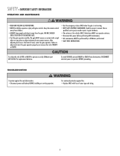
...; Replace ONLY with fuse of FIRE or INJURY to gate hardware. • The entrance is not moving. • KEEP GATES PROPERLY MAINTAINED. Pedestrians MUST use only LiftMaster part #K74-30762 for vehicles ONLY. The gate MUST reverse on contact with gate controls. SAFETY » IMPORTANT SAFETY INFORMATION OPERATION AND MAINTENANCE • READ AND FOLLOW ALL INSTRUCTIONS...
...; Replace ONLY with fuse of FIRE or INJURY to gate hardware. • The entrance is not moving. • KEEP GATES PROPERLY MAINTAINED. Pedestrians MUST use only LiftMaster part #K74-30762 for vehicles ONLY. The gate MUST reverse on contact with gate controls. SAFETY » IMPORTANT SAFETY INFORMATION OPERATION AND MAINTENANCE • READ AND FOLLOW ALL INSTRUCTIONS...

LA400 Manual
Page 8
Six Conductor, 9 feet (2.7 m) • Warning Sign (2) • Battery (2) • Plug-in Transformer (1) LA400-S (SECOND GATE OPERATOR ARM) • Motor Cable - Twelve Connectors (1) HARDWARE INVENTORY • Post Bracket (1) • Pull-to + 122° F... box. • Standard Control Box (1) • Hardware Bag (1) • Gate Operator Arm • Motor Cable - IP56 (1) • Phillips Head Mounting Screws (4) • Anchors (4) • Terminal Block - For Primary (Gate 1) and Secondary (Gate 2) installation the carton inventory is doubled except for a 90° opening 4 ...
Six Conductor, 9 feet (2.7 m) • Warning Sign (2) • Battery (2) • Plug-in Transformer (1) LA400-S (SECOND GATE OPERATOR ARM) • Motor Cable - Twelve Connectors (1) HARDWARE INVENTORY • Post Bracket (1) • Pull-to + 122° F... box. • Standard Control Box (1) • Hardware Bag (1) • Gate Operator Arm • Motor Cable - IP56 (1) • Phillips Head Mounting Screws (4) • Anchors (4) • Terminal Block - For Primary (Gate 1) and Secondary (Gate 2) installation the carton inventory is doubled except for a 90° opening 4 ...
LA400 Manual
Page 12
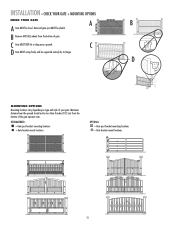
... and style of the gate operator arm. Gate and gate post MUST be supported entirely by its hinges. C D Gate MUST swing freely and be plumb. B Remove ANY/ALL wheels from the bottom of your gate. RECOMMENDED: = Gate post bracket mounting locations = Gate bracket mount locations OPTIONAL: = Gate post bracket mounting locations = Gate bracket mount locations 11 C Gate MUST NOT hit or...
... and style of the gate operator arm. Gate and gate post MUST be supported entirely by its hinges. C D Gate MUST swing freely and be plumb. B Remove ANY/ALL wheels from the bottom of your gate. RECOMMENDED: = Gate post bracket mounting locations = Gate bracket mount locations OPTIONAL: = Gate post bracket mounting locations = Gate bracket mount locations 11 C Gate MUST NOT hit or...
LA400 Manual
Page 14
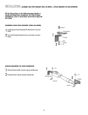
... BRACKET (PULL-TO-OPEN) 1 Assemble gate post bracket by placing Pull-to-Open bracket on the following pages display a typical Left-Hand Gate installation. INSTALLATION » ASSEMBLE GATE POST BRACKET (PULL-TO-OPEN) + ATTACH BRACKETS TO GATE OPERATOR All the illustrations on top of post ...bracket. 2 Insert the bolt through both brackets and secure with Push-to operator using pins and hairpin clips....
... BRACKET (PULL-TO-OPEN) 1 Assemble gate post bracket by placing Pull-to-Open bracket on the following pages display a typical Left-Hand Gate installation. INSTALLATION » ASSEMBLE GATE POST BRACKET (PULL-TO-OPEN) + ATTACH BRACKETS TO GATE OPERATOR All the illustrations on top of post ...bracket. 2 Insert the bolt through both brackets and secure with Push-to operator using pins and hairpin clips....
LA400 Manual
Page 16
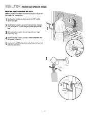
... Lock Washer Nut 15 Refer to page 11 for reference. The gate operator (arm) must be mounted several places on gate for mounting options. 1 Open the gate to -Open bracket and post bracket and secure with clamp. INSTALLATION » POSITION GATE OPERATOR ON GATE POSITION GATE OPERATOR ON GATE NOTE: The post bracket assembly can be level. 2 3 Mark mounting holes...
... Lock Washer Nut 15 Refer to page 11 for reference. The gate operator (arm) must be mounted several places on gate for mounting options. 1 Open the gate to -Open bracket and post bracket and secure with clamp. INSTALLATION » POSITION GATE OPERATOR ON GATE POSITION GATE OPERATOR ON GATE NOTE: The post bracket assembly can be level. 2 3 Mark mounting holes...
LA400 Manual
Page 17
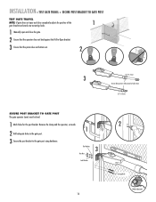
...2 Carriage Bolts Welder (Optional) Remove the clamp and the operator, set aside. 1 2 Drill adequate holes in the gate post. 3 Secure the post bracket to fully extend or fully retract. 1/2" (1.3 cm) SECURE POST BRACKET TO GATE POST The gate operator (arm) must be level. 1 Mark holes for the ...post bracket. INSTALLATION » TEST GATE TRAVEL + SECURE POST BRACKET TO GATE POST TEST GATE TRAVEL NOTE: If gate does not open and close completely adjust the position of...
...2 Carriage Bolts Welder (Optional) Remove the clamp and the operator, set aside. 1 2 Drill adequate holes in the gate post. 3 Secure the post bracket to fully extend or fully retract. 1/2" (1.3 cm) SECURE POST BRACKET TO GATE POST The gate operator (arm) must be level. 1 Mark holes for the ...post bracket. INSTALLATION » TEST GATE TRAVEL + SECURE POST BRACKET TO GATE POST TEST GATE TRAVEL NOTE: If gate does not open and close completely adjust the position of...
LA400 Manual
Page 18
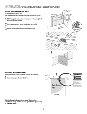
.... Some installations may move the gate to verify that are large enough for the gate bracket mounting hardware. 2 Secure the gate operator to the next page. 17 Inside Property Moving Gate Can Cause Injury or Death KEEP CLEAR! INSTALLATION » SECURE GATE BRACKET TO GATE + WARNING SIGN PLACEMENT SECURE GATE BRACKET TO GATE The gate operator (arm) must use separate entrance...
.... Some installations may move the gate to verify that are large enough for the gate bracket mounting hardware. 2 Secure the gate operator to the next page. 17 Inside Property Moving Gate Can Cause Injury or Death KEEP CLEAR! INSTALLATION » SECURE GATE BRACKET TO GATE + WARNING SIGN PLACEMENT SECURE GATE BRACKET TO GATE The gate operator (arm) must use separate entrance...

LA400 Manual
Page 19
... Knock Outs Knock Outs Knock Outs 7 A. INSTALLATION » STANDARD CONTROL BOX MOUNT THE CONTROL BOX The control box MUST be mounted within 5 feet (1.5 m) of the gate operator. Knock Outs B.
... Knock Outs Knock Outs Knock Outs 7 A. INSTALLATION » STANDARD CONTROL BOX MOUNT THE CONTROL BOX The control box MUST be mounted within 5 feet (1.5 m) of the gate operator. Knock Outs B.
LA400 Manual
Page 21
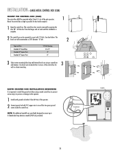
... GATE 2 ON OFF AUTO OPEN LOW BATT OFF MAX SINGLE BUTTON TIMER TO CLOSE OPEN CONTROL INPUTS SINGLE BUTTON OFF MAX RESET STOP CTRL PWR CTRL PWR SHADOW INTERRUPT CHGR OVLD CTRL PWR AC PWR /SOLAR LOOP INPUTS until the installation is important to the operator. 1 Install earth ground rod within... designed to mount up to one of the two green ground screws inside the control box. Use knock outs located at the 4 corners of the gate operator. 1 90° Mount the control box as high as possible for 3 wall or column mounting. See chart below. Ground Screw Standoffs ALARM LOCK ...
... GATE 2 ON OFF AUTO OPEN LOW BATT OFF MAX SINGLE BUTTON TIMER TO CLOSE OPEN CONTROL INPUTS SINGLE BUTTON OFF MAX RESET STOP CTRL PWR CTRL PWR SHADOW INTERRUPT CHGR OVLD CTRL PWR AC PWR /SOLAR LOOP INPUTS until the installation is important to the operator. 1 Install earth ground rod within... designed to mount up to one of the two green ground screws inside the control box. Use knock outs located at the 4 corners of the gate operator. 1 90° Mount the control box as high as possible for 3 wall or column mounting. See chart below. Ground Screw Standoffs ALARM LOCK ...

LA400 Manual
Page 22
... located inside the control box. The second receptacle can be removed to power up additional gate operator accessories. ALARM LOCK SOL GND MAGR GATE 1 BR GR WH YL BL RD ACCESSORY POWER 12 V BR GR WH YL BL RD GATE 2 LEARN XMITTER ON OFF LOCK / BIPA RT DELAY CLOSE EDGE OPEN EDGE/ PHOTO ...OPEN PHOTO SET OPEN LIMIT GATE 1 CLOSE PHOTO SET CLOSE LIMIT LEARN LIMITS FORCE GATE 2 ON OFF AUTO OPEN LOW BATT OFF MAX SINGLE BUTTON TIMER TO CLOSE OPEN CONTROL INPUTS SINGLE BUTTON RESET OFF MAX STOP CTRL PWR ...
... located inside the control box. The second receptacle can be removed to power up additional gate operator accessories. ALARM LOCK SOL GND MAGR GATE 1 BR GR WH YL BL RD ACCESSORY POWER 12 V BR GR WH YL BL RD GATE 2 LEARN XMITTER ON OFF LOCK / BIPA RT DELAY CLOSE EDGE OPEN EDGE/ PHOTO ...OPEN PHOTO SET OPEN LIMIT GATE 1 CLOSE PHOTO SET CLOSE LIMIT LEARN LIMITS FORCE GATE 2 ON OFF AUTO OPEN LOW BATT OFF MAX SINGLE BUTTON TIMER TO CLOSE OPEN CONTROL INPUTS SINGLE BUTTON RESET OFF MAX STOP CTRL PWR ...
LA400 Manual
Page 23
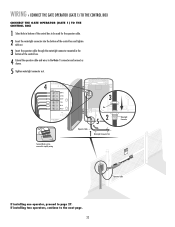
...; CONNECT THE GATE OPERATOR (GATE 1) TO THE CONTROL BOX CONNECT THE GATE OPERATOR (GATE 1) TO THE CONTROL BOX 1 Select hole in the bottom of the control box. 4 Extend the operator cable and wires to the Gate 1 connector and connect as shown. 5 Tighten watertight connector nut. Watertight Connector KtDpTPiMmlheEoaidEyseneoPoieswntnvtCirtttliLiehhrIaanEteonnncAusggjchtRauemiplt!GdeirursGriysoaeaaftrrnoteteuorwaoesmv.rapeereaChnsDryeiiacnapmtelgeean.oasrtahvottCeeehnaglaeytanuattenrsayonerce Operator Cable If installing one operator, proceed to the...
...; CONNECT THE GATE OPERATOR (GATE 1) TO THE CONTROL BOX CONNECT THE GATE OPERATOR (GATE 1) TO THE CONTROL BOX 1 Select hole in the bottom of the control box. 4 Extend the operator cable and wires to the Gate 1 connector and connect as shown. 5 Tighten watertight connector nut. Watertight Connector KtDpTPiMmlheEoaidEyseneoPoieswntnvtCirtttliLiehhrIaanEteonnncAusggjchtRauemiplt!GdeirursGriysoaeaaftrrnoteteuorwaoesmv.rapeereaChnsDryeiiacnapmtelgeean.oasrtahvottCeeehnaglaeytanuattenrsayonerce Operator Cable If installing one operator, proceed to the...

LA400 Manual
Page 25
WIRING » CONNECT THE GATE OPERATOR (GATE 2) TO THE CONTROL BOX (MODEL LA400-S ONLY) CONNECT THE GATE OPERATOR (GATE 2) TO THE CONTROL BOX (MODEL LA400-S ONLY) Before digging, contact local underground utility locating companies. 1 Trench across driveway to control box using watertight connector nut. Insert extension cable through watertight connector ...
WIRING » CONNECT THE GATE OPERATOR (GATE 2) TO THE CONTROL BOX (MODEL LA400-S ONLY) CONNECT THE GATE OPERATOR (GATE 2) TO THE CONTROL BOX (MODEL LA400-S ONLY) Before digging, contact local underground utility locating companies. 1 Trench across driveway to control box using watertight connector nut. Insert extension cable through watertight connector ...

LA400 Manual
Page 26
WIRING » JUNCTION BOX (MODEL LA400-S ONLY) JUNCTION BOX The following items are required to be used for the watertight connectors. 2 3 Mount the junction box within 5 feet (1.5 m) of second operator. Drill two holes in the bottom ... Box with connector nut. 3 Junction Box Cover Junction Box KKnoncokckOOutut JJuunncctitoionnBBooxx 5'W(1it.h5inm) Gate Operator (Gate 2) Junction Box Extension Cable ConCnoencnetcotorr Nut 6 Nut CCononnecntoer cNtuot r Nut Extension ExtCenasibonleCable 25 5 WirWeCotaintgenrhetictgtohrt Connector 4 WCoWCantoneierrntecitngothiregt chttor...
WIRING » JUNCTION BOX (MODEL LA400-S ONLY) JUNCTION BOX The following items are required to be used for the watertight connectors. 2 3 Mount the junction box within 5 feet (1.5 m) of second operator. Drill two holes in the bottom ... Box with connector nut. 3 Junction Box Cover Junction Box KKnoncokckOOutut JJuunncctitoionnBBooxx 5'W(1it.h5inm) Gate Operator (Gate 2) Junction Box Extension Cable ConCnoencnetcotorr Nut 6 Nut CCononnecntoer cNtuot r Nut Extension ExtCenasibonleCable 25 5 WirWeCotaintgenrhetictgtohrt Connector 4 WCoWCantoneierrntecitngothiregt chttor...

LA400 Manual
Page 45
... 20 Amp (1), 15 Amp (2) Receiver Module - 390 MHz Receiver Module - 315 MHz Reset Switch (XLM Control Box) Alarm (XLM Control Box) GATE OPERATOR ARM 22 33 ITEM PART # DESCRIPTION QTY 1 41ASWG-442SA Release Lever 1 2 41ASWG-438SA Motor with Limit 1 11 Switch Harness 3 41ASWG-0014SA...1 Not Shown 41ASWG-0119 Release Key 1 K77-19130 Hardware Bag Complete with: Gate bracket, post bracket, Pull-to the parts lists below for replacement parts available for your operator. REPAIR PARTS » CONTROL BOX + GATE OPERATOR ARM CONTROL BOX Refer to -Open bracket and hardware 44 44
... 20 Amp (1), 15 Amp (2) Receiver Module - 390 MHz Receiver Module - 315 MHz Reset Switch (XLM Control Box) Alarm (XLM Control Box) GATE OPERATOR ARM 22 33 ITEM PART # DESCRIPTION QTY 1 41ASWG-442SA Release Lever 1 2 41ASWG-438SA Motor with Limit 1 11 Switch Harness 3 41ASWG-0014SA...1 Not Shown 41ASWG-0119 Release Key 1 K77-19130 Hardware Bag Complete with: Gate bracket, post bracket, Pull-to the parts lists below for replacement parts available for your operator. REPAIR PARTS » CONTROL BOX + GATE OPERATOR ARM CONTROL BOX Refer to -Open bracket and hardware 44 44
LA400 Manual
Page 47
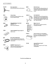
...gate open. Includes mounting hardware. ACCESSORIES 50-19503 Push-to-Open Bracket Used toOPEN allow for a Open, Close, Stop command of the gate. OPEN LM202 02101 OPEN OPEN OPEN 370LM 1-Button Station: Steel enclosure wired station will allow the gate operator to operate gate... by entering a password on a specially designed keypad. Magnetic Gate Lock: ... battery for the operator. To order visit www.liftmaster.com 46 Fail safe operation keeps gate locked if power ...gate, providing for increasing the effective range of cable. The model...
...gate open. Includes mounting hardware. ACCESSORIES 50-19503 Push-to-Open Bracket Used toOPEN allow for a Open, Close, Stop command of the gate. OPEN LM202 02101 OPEN OPEN OPEN 370LM 1-Button Station: Steel enclosure wired station will allow the gate operator to operate gate... by entering a password on a specially designed keypad. Magnetic Gate Lock: ... battery for the operator. To order visit www.liftmaster.com 46 Fail safe operation keeps gate locked if power ...gate, providing for increasing the effective range of cable. The model...


