

LA400 Manual
Page 6
... force beyond minimum amount required to close gate cycles. • Locate entrapment protection devices to protect between moving gate and RIGID objects, such as posts. • A swinging gate shall NOT open and close gate. • NEVER use only LiftMaster part #K74-30762 for disposal instructions. Upon... to protect anyone who may be performed until disconnecting the electrical power and locking-out the power via the operator power switch. To prevent SERIOUS INJURY or DEATH from a moving gate: • Install warning signs on a dedicated circuit and well protected. ...
... force beyond minimum amount required to close gate cycles. • Locate entrapment protection devices to protect between moving gate and RIGID objects, such as posts. • A swinging gate shall NOT open and close gate. • NEVER use only LiftMaster part #K74-30762 for disposal instructions. Upon... to protect anyone who may be performed until disconnecting the electrical power and locking-out the power via the operator power switch. To prevent SERIOUS INJURY or DEATH from a moving gate: • Install warning signs on a dedicated circuit and well protected. ...

LA400 Manual
Page 8
... • Flat Washer 5/16" (5) • Flat Washer 3/8" (5) • Lock Washer 5/16" (5) • Lock Washer 3/8" (5) • Gate Mounting Bracket (1) • Hairpin Clip (2) • Pin (2) • Hex Bolt... 3/8"-16 X 1-1/2" (1) • Bolt 2-3/4" (2) • Keylock Cap (1) • Keys (2) 7 Six Conductor, 40 feet (12.2 m) • Junction Box - Six Conductor, 9 feet (2.7 m) • Warning Sign (2) • Battery (2) • Plug-in Transformer (1) LA400-S (SECOND GATE...
... • Flat Washer 5/16" (5) • Flat Washer 3/8" (5) • Lock Washer 5/16" (5) • Lock Washer 3/8" (5) • Gate Mounting Bracket (1) • Hairpin Clip (2) • Pin (2) • Hex Bolt... 3/8"-16 X 1-1/2" (1) • Bolt 2-3/4" (2) • Keylock Cap (1) • Keys (2) 7 Six Conductor, 40 feet (12.2 m) • Junction Box - Six Conductor, 9 feet (2.7 m) • Warning Sign (2) • Battery (2) • Plug-in Transformer (1) LA400-S (SECOND GATE...
LA400 Manual
Page 13
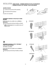
...-HAND GATE Release Lever OR DETERMINE POSITION OF THE "OPTIONAL" PUSH-TO-OPEN BRACKET (NOT PROVIDED. INSTALLATION » MANUAL RELEASE + DETERMINE POSITION OF THE PULL-TO-OPEN BRACKET + DETERMINE POSITION OF THE "OPTIONAL" PUSH-TO-OPEN BRACKET MANUAL RELEASE 1 Insert the key into the lock and turn it 180° counterclockwise. 2 Turn...
...-HAND GATE Release Lever OR DETERMINE POSITION OF THE "OPTIONAL" PUSH-TO-OPEN BRACKET (NOT PROVIDED. INSTALLATION » MANUAL RELEASE + DETERMINE POSITION OF THE PULL-TO-OPEN BRACKET + DETERMINE POSITION OF THE "OPTIONAL" PUSH-TO-OPEN BRACKET MANUAL RELEASE 1 Insert the key into the lock and turn it 180° counterclockwise. 2 Turn...
LA400 Manual
Page 14
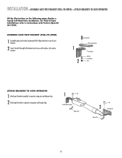
...-Open bracket on the following pages display a typical Left-Hand Gate installation. For Push-to-Open installations refer to instructions with washer, lock washer and nut. 1 2 HeexxBBolot l3t/38/"8" Extension PBurlla-tcok-Oepten Bracket PPoostsBtrBacrkaectket WWaashsehrer LLoockckWaWshaesr her NNuut t ATTACH BRACKETS TO GATE OPERATOR 1 Attach post bracket assembly to operator using pins and...
...-Open bracket on the following pages display a typical Left-Hand Gate installation. For Push-to-Open installations refer to instructions with washer, lock washer and nut. 1 2 HeexxBBolot l3t/38/"8" Extension PBurlla-tcok-Oepten Bracket PPoostsBtrBacrkaectket WWaashsehrer LLoockckWaWshaesr her NNuut t ATTACH BRACKETS TO GATE OPERATOR 1 Attach post bracket assembly to operator using pins and...
LA400 Manual
Page 16
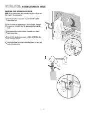
... desired open position (no greater than 100°) and hold operator against gate. 2 Place the operator arm against gate post at the desired position. Temporarily secure the gate bracket using a clamp. 4 Align the Pull-to-Open bracket to a position as CLOSE AS ...reference. INSTALLATION » POSITION GATE OPERATOR ON GATE POSITION GATE OPERATOR ON GATE NOTE: The post bracket assembly can be level. 2 3 Mark mounting holes on the gate post. Refer to -Open bracket and post bracket and secure with clamp. Temporarily secure gate post bracket with washer, lock washer and nut. 1 3 ...
... desired open position (no greater than 100°) and hold operator against gate. 2 Place the operator arm against gate post at the desired position. Temporarily secure the gate bracket using a clamp. 4 Align the Pull-to-Open bracket to a position as CLOSE AS ...reference. INSTALLATION » POSITION GATE OPERATOR ON GATE POSITION GATE OPERATOR ON GATE NOTE: The post bracket assembly can be level. 2 3 Mark mounting holes on the gate post. Refer to -Open bracket and post bracket and secure with clamp. Temporarily secure gate post bracket with washer, lock washer and nut. 1 3 ...
LA400 Manual
Page 17
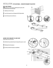
.... 1 Mark holes for the post bracket. Flat Washers 3 Hex Nuts Lock Washers 16 2 Carriage Bolts Welder (Optional) INSTALLATION » TEST GATE TRAVEL + SECURE POST BRACKET TO GATE POST TEST GATE TRAVEL NOTE: If gate does not open and close completely adjust the position of the 1 gate bracket and mark new mounting holes. 1 Manually open and close...
.... 1 Mark holes for the post bracket. Flat Washers 3 Hex Nuts Lock Washers 16 2 Carriage Bolts Welder (Optional) INSTALLATION » TEST GATE TRAVEL + SECURE POST BRACKET TO GATE POST TEST GATE TRAVEL NOTE: If gate does not open and close completely adjust the position of the 1 gate bracket and mark new mounting holes. 1 Manually open and close...
LA400 Manual
Page 18
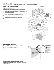
... enough for the second gate before proceeding to verify that it opens and closes fully. Reinforcement Area 1 Operator Angle Iron OR Wood OR Flat Bar Welder (Optional) Hex Nut Lock Washer Flat Washer 2 Gate Bracket Hex Bolt 3 WARNING... SIGN PLACEMENT Warning signs MUST be level. Some installations may move the gate to the next page. 17 Inside Property Moving Gate Can Cause Injury or Death KEEP CLEAR! INSTALLATION » SECURE GATE BRACKET TO GATE + WARNING SIGN PLACEMENT SECURE GATE BRACKET TO GATE The gate...
... enough for the second gate before proceeding to verify that it opens and closes fully. Reinforcement Area 1 Operator Angle Iron OR Wood OR Flat Bar Welder (Optional) Hex Nut Lock Washer Flat Washer 2 Gate Bracket Hex Bolt 3 WARNING... SIGN PLACEMENT Warning signs MUST be level. Some installations may move the gate to the next page. 17 Inside Property Moving Gate Can Cause Injury or Death KEEP CLEAR! INSTALLATION » SECURE GATE BRACKET TO GATE + WARNING SIGN PLACEMENT SECURE GATE BRACKET TO GATE The gate...
LA400 Manual
Page 21
... YL BL RD GATE 2 ALARM LOCK SOL GND MAGR GATE 1 BR GR WH YL LEARN XMBITLTER RD ACCESSORY POWER 12 V GATE 2 SEBTR OPEN LIMGITR WH YL BL RD LEARN XMITTER ON OFF LOCK / BIPA RT DELAY OPE ON OFF LOCK / BIPA RT DELAY SET OPEN LIMIT GATE 1 SET CLOSE LIMIT LEARN LIMITS GATE 2 GATE 1 SET CLOSE...OVLD CTRL PWR AC PWR /SOLAR LOOP INPUTS 20 Lift the door from the hinges and ALARM LOCK GATE 1 setSOL GND MAGR LEARN XMITTER ON OFF LOCK / BIPA RT DELAY BR GR WH YL BL GATE 1 RD SET OPEN LIMIT SET CLOSE LIMIT LEARN LIMITS aside CLOSE EDGE OPEN EDGE/ PHOTO ...
... YL BL RD GATE 2 ALARM LOCK SOL GND MAGR GATE 1 BR GR WH YL LEARN XMBITLTER RD ACCESSORY POWER 12 V GATE 2 SEBTR OPEN LIMGITR WH YL BL RD LEARN XMITTER ON OFF LOCK / BIPA RT DELAY OPE ON OFF LOCK / BIPA RT DELAY SET OPEN LIMIT GATE 1 SET CLOSE LIMIT LEARN LIMITS GATE 2 GATE 1 SET CLOSE...OVLD CTRL PWR AC PWR /SOLAR LOOP INPUTS 20 Lift the door from the hinges and ALARM LOCK GATE 1 setSOL GND MAGR LEARN XMITTER ON OFF LOCK / BIPA RT DELAY BR GR WH YL BL GATE 1 RD SET OPEN LIMIT SET CLOSE LIMIT LEARN LIMITS aside CLOSE EDGE OPEN EDGE/ PHOTO ...

LA400 Manual
Page 22
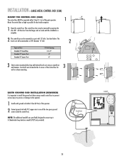
... WH YL BL RD ACCESSORY POWER 12 V BR GR WH YL BL RD GATE 2 LEARN XMITTER ON OFF LOCK / BIPA RT DELAY CLOSE EDGE OPEN EDGE/ PHOTO OPEN PHOTO SET OPEN LIMIT GATE 1 CLOSE PHOTO SET CLOSE LIMIT LEARN LIMITS FORCE GATE 2 ON OFF AUTO OPEN LOW BATT OFF MAX SINGLE BUTTON TIMER TO... the knock out in the bottom of the receptacles is for the standard control box. The second receptacle can be removed to power up additional gate operator accessories. One of the control box based on the application requirements. 2 Depending on the voltage and application the 120 Vac access panel may be...
... WH YL BL RD ACCESSORY POWER 12 V BR GR WH YL BL RD GATE 2 LEARN XMITTER ON OFF LOCK / BIPA RT DELAY CLOSE EDGE OPEN EDGE/ PHOTO OPEN PHOTO SET OPEN LIMIT GATE 1 CLOSE PHOTO SET CLOSE LIMIT LEARN LIMITS FORCE GATE 2 ON OFF AUTO OPEN LOW BATT OFF MAX SINGLE BUTTON TIMER TO... the knock out in the bottom of the receptacles is for the standard control box. The second receptacle can be removed to power up additional gate operator accessories. One of the control box based on the application requirements. 2 Depending on the voltage and application the 120 Vac access panel may be...

LA400 Manual
Page 24
... there is being used on a gate, the gate with a decorative overlapping piece on the outside of the gate. This gate is OFF. Primary Gate OUTSIDE PROPERTY 23 WIRING » SET THE BIPART DELAY (MODEL LA400-S ONLY) SET THE BIPART DELAY (MODEL LA400-S ONLY) In some dual gate installations, one gate or if using a solenoid lock, for the control box, then...
... there is being used on a gate, the gate with a decorative overlapping piece on the outside of the gate. This gate is OFF. Primary Gate OUTSIDE PROPERTY 23 WIRING » SET THE BIPART DELAY (MODEL LA400-S ONLY) SET THE BIPART DELAY (MODEL LA400-S ONLY) In some dual gate installations, one gate or if using a solenoid lock, for the control box, then...
LA400 Manual
Page 32
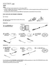
... operator. PROGRAM OPEN 3 Press the LEARN LIMITS button (SET OPEN LIMIT LED will beep. DIAGNOSTIC GATE 1 SET CLOSE 5 Press the GATE 2 right button to be closed first if there is overlap or a gate lock is being used. • The programming can be exited at any time by turning the release ...lever clockwise 180°, then turning the key clockwise 180°. DUAL GATE (LEFT-SIDE PRIMARY OPERATOR) 1 Close the gate. 2 Engage the operator by pressing the...
... operator. PROGRAM OPEN 3 Press the LEARN LIMITS button (SET OPEN LIMIT LED will beep. DIAGNOSTIC GATE 1 SET CLOSE 5 Press the GATE 2 right button to be closed first if there is overlap or a gate lock is being used. • The programming can be exited at any time by turning the release ...lever clockwise 180°, then turning the key clockwise 180°. DUAL GATE (LEFT-SIDE PRIMARY OPERATOR) 1 Close the gate. 2 Engage the operator by pressing the...

LA400 Manual
Page 33
...When the SET CLOSE LIMITS LED blinks, press the GATE 2 right button to open and close the right operator. If the problem continues, see Troubleshooting section.) Test the limits by pressing the SBC to be closed first if there is overlap or a gate lock is being used. • The programming can ...be connected to move the left button to GATE 1 so it will start moving before the other gate; GATE 2 may need to open the right operator. Programming times-out automatically after...
...When the SET CLOSE LIMITS LED blinks, press the GATE 2 right button to open and close the right operator. If the problem continues, see Troubleshooting section.) Test the limits by pressing the SBC to be closed first if there is overlap or a gate lock is being used. • The programming can ...be connected to move the left button to GATE 1 so it will start moving before the other gate; GATE 2 may need to open the right operator. Programming times-out automatically after...

LA400 Manual
Page 39
...(5 cm) square post. PIN:G65ME120C5) Miller MG020 2-wire electric edge for secondary entrapment protection. Solenoid Lock (optional) MAGLOCK NO C NC ACCESSORY POWER 24V Maglock (optional) MAGLOCK NO C NC (not provided)...SAFETY ACCESSORIES FOR SECONDARY ENTRAPMENT PROTECTION The following devices are acceptable for Safety Accessories for gates. These devices have been provided for 2 inch (5 cm) round post. MODEL CPS... and mounting brackets - 30 feet (9 m) Ranges VOLTAGE +24 Vdc Emitter with the LA400 to control box depending on wire gauge and distance - 300 mA accessory power, 75 ...
...(5 cm) square post. PIN:G65ME120C5) Miller MG020 2-wire electric edge for secondary entrapment protection. Solenoid Lock (optional) MAGLOCK NO C NC ACCESSORY POWER 24V Maglock (optional) MAGLOCK NO C NC (not provided)...SAFETY ACCESSORIES FOR SECONDARY ENTRAPMENT PROTECTION The following devices are acceptable for Safety Accessories for gates. These devices have been provided for 2 inch (5 cm) round post. MODEL CPS... and mounting brackets - 30 feet (9 m) Ranges VOLTAGE +24 Vdc Emitter with the LA400 to control box depending on wire gauge and distance - 300 mA accessory power, 75 ...
LA400 Manual
Page 40
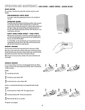
... is now engaged. 39 2 3 2 3 This locks the release lever. 3 Remove the key and store in manual mode and the gate can be disengaged from the gate. OPERATOR ALARM The operator alarm will sound under the following condition: If gate encounters two consecutive obstructions, before reaching the open or ...for any extended period of the remote control button will close the gate. During the open position, activation of time you wish to 5 minutes) and the control board will require resetting. RELEASE 1 Insert the key into the lock. 2 Turn the key counter-clockwise 180°. 3 Turn ...
... is now engaged. 39 2 3 2 3 This locks the release lever. 3 Remove the key and store in manual mode and the gate can be disengaged from the gate. OPERATOR ALARM The operator alarm will sound under the following condition: If gate encounters two consecutive obstructions, before reaching the open or ...for any extended period of the remote control button will close the gate. During the open position, activation of time you wish to 5 minutes) and the control board will require resetting. RELEASE 1 Insert the key into the lock. 2 Turn the key counter-clockwise 180°. 3 Turn ...
LA400 Manual
Page 43
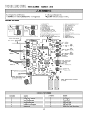
... For continued protection against fire and electrocution: • DISCONNECT power and battery BEFORE installing or servicing operator. WIRING DIAGRAM Solenoid Lock (optional) MAGLOCK NO C NC Maglock (optional) MAGLOCK NO C NC (not provided) Flashing Strobe (optional) (not provided...) 1. TRANSFORMER INPUT 10. BATTERY INPUT #2 17. TIMER TO CLOSE SET BLUE YELLOW J 1 BLACK RED BLACK RED Siren (optional) Fault Alarm GATE 1 GATE 2 14 13 B R N G R N W HT YE L B L U R E D 12 11 B R N G R N W HT YE L B L U R E D 10 (OR OPTIONAL EARTH ...
... For continued protection against fire and electrocution: • DISCONNECT power and battery BEFORE installing or servicing operator. WIRING DIAGRAM Solenoid Lock (optional) MAGLOCK NO C NC Maglock (optional) MAGLOCK NO C NC (not provided) Flashing Strobe (optional) (not provided...) 1. TRANSFORMER INPUT 10. BATTERY INPUT #2 17. TIMER TO CLOSE SET BLUE YELLOW J 1 BLACK RED BLACK RED Siren (optional) Fault Alarm GATE 1 GATE 2 14 13 B R N G R N W HT YE L B L U R E D 12 11 B R N G R N W HT YE L B L U R E D 10 (OR OPTIONAL EARTH ...
LA400 Manual
Page 47
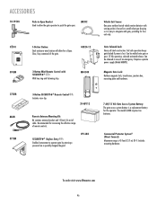
... so it is lost. The model LA400 requires two batteries. Fail safe operation keeps gate locked if power is easy to integrate with SECURITY✚® : With key ring and fastening strip. To order visit www.liftmaster.com 46 CPS-LN4 7 AH/12 Vdc Gate Access System Battery: The gate access system battery is 45 feet...
... so it is lost. The model LA400 requires two batteries. Fail safe operation keeps gate locked if power is easy to integrate with SECURITY✚® : With key ring and fastening strip. To order visit www.liftmaster.com 46 CPS-LN4 7 AH/12 Vdc Gate Access System Battery: The gate access system battery is 45 feet...

LA400 Push to Open Addendum Manual
Page 1
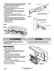
... dimensions (Figure 2). 4. Mount gate bracket to actuator side of operator with flat washer, lock washer, and nut to -Open Bracket Post Bracket 3/8" Flat Washer 3/8" Lock Washer 3/8" Nut Center of operator. With gate in open bracket into slot on motor side of Gate Hinge Figure 3 Pin Hex Bolt... Nut Hairpin Clip 5/16" Hex Bolt 7-3/4" 90° 7-3/4" Special Post Pivot Bracket for Push-to-Open Installation Pin Gate Bracket Hairpin Clip Fasten with lock washer, flat washer and nut (Figure 1). 2. Insert pin and hairpin clips to post using C clamp. 3. Figure 1 Figure 2 Push-to...
... dimensions (Figure 2). 4. Mount gate bracket to actuator side of operator with flat washer, lock washer, and nut to -Open Bracket Post Bracket 3/8" Flat Washer 3/8" Lock Washer 3/8" Nut Center of operator. With gate in open bracket into slot on motor side of Gate Hinge Figure 3 Pin Hex Bolt... Nut Hairpin Clip 5/16" Hex Bolt 7-3/4" 90° 7-3/4" Special Post Pivot Bracket for Push-to-Open Installation Pin Gate Bracket Hairpin Clip Fasten with lock washer, flat washer and nut (Figure 1). 2. Insert pin and hairpin clips to post using C clamp. 3. Figure 1 Figure 2 Push-to...
LA400 Push to Open Addendum Manual
Page 2
...Reconnect power to cross member with 3/8"-16 x 6" carriage bolts, flat washers, lock washers and nuts. NOTE: All four mounting holes must be level Fence Post Gate in OPEN Position Gate Bracket C Clamp Gate in the vertical center of post bracket slots (Figure 5). 10. Remove brackets ...and mounting plate. 5. 7. Reattach operator to operator. 2. Disconnect power to gate. Reconnect all quick connect terminals in retracted position, clamp bracket to gate post with 5/16" carriage bolts, flat washers, lock washers and nuts. 13. Tighten in place, remove clevis pins and washers...
...Reconnect power to cross member with 3/8"-16 x 6" carriage bolts, flat washers, lock washers and nuts. NOTE: All four mounting holes must be level Fence Post Gate in OPEN Position Gate Bracket C Clamp Gate in the vertical center of post bracket slots (Figure 5). 10. Remove brackets ...and mounting plate. 5. 7. Reattach operator to operator. 2. Disconnect power to gate. Reconnect all quick connect terminals in retracted position, clamp bracket to gate post with 5/16" carriage bolts, flat washers, lock washers and nuts. 13. Tighten in place, remove clevis pins and washers...


