
LA400 Manual
Page 1
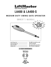
The operator can be used in Class I, Class II and Class III applications. 2 YEAR WARRANTY Radio Receiver Built on Board 315 MHz LA400 & LA400-S MEDIUM DUTY SWING GATE OPERATOR OWNER'S MANUAL MeBtOoLaaxplrtC(giXooennLMatrl)ol Serial # Primary Arm Serial # Secondary Arm Serial # Control Box Installation Date The LA400 is intended for use with vehicular swing gates.
The operator can be used in Class I, Class II and Class III applications. 2 YEAR WARRANTY Radio Receiver Built on Board 315 MHz LA400 & LA400-S MEDIUM DUTY SWING GATE OPERATOR OWNER'S MANUAL MeBtOoLaaxplrtC(giXooennLMatrl)ol Serial # Primary Arm Serial # Secondary Arm Serial # Control Box Installation Date The LA400 is intended for use with vehicular swing gates.

LA400 Manual
Page 2
... Brackets to Gate Operator Determine Mounting Location Measuring and Marking for the Gate Bracket Position Gate Operator on Gate Test Gate Travel Secure Post Bracket to Gate Post Secure Gate Bracket to Gate Warning Sign Placement Standard Control Box Large Metal Control Box (XLM) WIRING Connect the Gate Operator (Gate 1) to the Control Box Set the Bipart Delay (Model LA400-S Only) Connect the Gate Operator (Gate 2) to...
... Brackets to Gate Operator Determine Mounting Location Measuring and Marking for the Gate Bracket Position Gate Operator on Gate Test Gate Travel Secure Post Bracket to Gate Post Secure Gate Bracket to Gate Warning Sign Placement Standard Control Box Large Metal Control Box (XLM) WIRING Connect the Gate Operator (Gate 1) to the Control Box Set the Bipart Delay (Model LA400-S Only) Connect the Gate Operator (Gate 2) to...

LA400 Manual
Page 3
... therewith. This system must sense and initiate the reverse of the gate within the operator. SAFETY ACCESSORY SELECTION All UL325 compliant LiftMaster gate operators will accept external entrapment protection devices to warn pedestrians of the dangers of motorized gate systems. 2 Non-contact sensors such as gate edges. SAFETY » UL325 MODEL CLASSIFICATIONS CLASS I ) you must provide the...
... therewith. This system must sense and initiate the reverse of the gate within the operator. SAFETY ACCESSORY SELECTION All UL325 compliant LiftMaster gate operators will accept external entrapment protection devices to warn pedestrians of the dangers of motorized gate systems. 2 Non-contact sensors such as gate edges. SAFETY » UL325 MODEL CLASSIFICATIONS CLASS I ) you must provide the...

LA400 Manual
Page 4
... be located and its arc of travel of non-contact sensor for exposed rollers. 5. Reference owner's manual regarding placement of the vehicular gate. 6. For a gate operator utilizing a contact sensor such as at the bottom edge of 4 feet (1.2 m) above the ground at any moving . A hard... installation of the adjacent fence that enough clearance is supplied between the sensor and the gate operator is intended for vehicles. The operator is not subject to operate the controls. The gate must take into account the possible hazards associated with a separate access opening shall be ...
... be located and its arc of travel of non-contact sensor for exposed rollers. 5. Reference owner's manual regarding placement of the vehicular gate. 6. For a gate operator utilizing a contact sensor such as at the bottom edge of 4 feet (1.2 m) above the ground at any moving . A hard... installation of the adjacent fence that enough clearance is supplied between the sensor and the gate operator is intended for vehicles. The operator is not subject to operate the controls. The gate must take into account the possible hazards associated with a separate access opening shall be ...

LA400 Manual
Page 5
... F2200 for shall be guarded or covered. vertically project no more than 8 feet (2.44 m) function. SAFETY » GATE CONSTRUCTION INFORMATION Vehicular gates should be installed in the open position. 2. that the gate covers in accordance with a powered gate operator. 3.2 The following provisions shall apply to Class 1, Class II and Class III vehicular 2.3 Any existing automated...
... F2200 for shall be guarded or covered. vertically project no more than 8 feet (2.44 m) function. SAFETY » GATE CONSTRUCTION INFORMATION Vehicular gates should be installed in the open position. 2. that the gate covers in accordance with a powered gate operator. 3.2 The following provisions shall apply to Class 1, Class II and Class III vehicular 2.3 Any existing automated...
LA400 Manual
Page 7
...700;s manual. To avoid SERIOUS personal INJURY or DEATH from the gate. Pedestrians MUST use only LiftMaster part #K74-30762 for vehicles ONLY. The gate MUST reverse on contact with gate controls. TROUBLESHOOTING To protect against fire: • Replace ONLY with...retest the gate operator. For continued protection against fire and electrocution: • Disconnect power and battery BEFORE installing or servicing operator. NO ONE SHOULD CROSS THE PATH OF THE MOVING GATE. • Test the gate operator monthly. SAFETY » IMPORTANT SAFETY INFORMATION OPERATION AND ...
...700;s manual. To avoid SERIOUS personal INJURY or DEATH from the gate. Pedestrians MUST use only LiftMaster part #K74-30762 for vehicles ONLY. The gate MUST reverse on contact with gate controls. TROUBLESHOOTING To protect against fire: • Replace ONLY with...retest the gate operator. For continued protection against fire and electrocution: • Disconnect power and battery BEFORE installing or servicing operator. NO ONE SHOULD CROSS THE PATH OF THE MOVING GATE. • Test the gate operator monthly. SAFETY » IMPORTANT SAFETY INFORMATION OPERATION AND ...

LA400 Manual
Page 8
... Conductor, 40 feet (12.2 m) • Junction Box - Six Conductor, 9 feet (2.7 m) • Warning Sign (2) • Battery (2) • Plug-in Transformer (1) LA400-S (SECOND GATE OPERATOR ARM) • Motor Cable - IP56 (1) • Phillips Head Mounting Screws (4) • Anchors (4) • Terminal Block - Twelve Connectors (1) HARDWARE INVENTORY • Post Bracket (1) • Pull-to + ...
... Conductor, 40 feet (12.2 m) • Junction Box - Six Conductor, 9 feet (2.7 m) • Warning Sign (2) • Battery (2) • Plug-in Transformer (1) LA400-S (SECOND GATE OPERATOR ARM) • Motor Cable - IP56 (1) • Phillips Head Mounting Screws (4) • Anchors (4) • Terminal Block - Twelve Connectors (1) HARDWARE INVENTORY • Post Bracket (1) • Pull-to + ...
LA400 Manual
Page 12
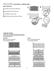
.... Minimum distance from the ground should not be level. B Remove ANY/ALL wheels from the bottom of your gate. INSTALLATION » CHECK YOUR GATE + MOUNTING OPTIONS CHECK YOUR GATE A B A Gate MUST be less than 4 inches (10.2 cm) from the bottom of the gate operator arm. D MOUNTING OPTIONS Mounting locations vary depending on type and style of...
.... Minimum distance from the ground should not be level. B Remove ANY/ALL wheels from the bottom of your gate. INSTALLATION » CHECK YOUR GATE + MOUNTING OPTIONS CHECK YOUR GATE A B A Gate MUST be less than 4 inches (10.2 cm) from the bottom of the gate operator arm. D MOUNTING OPTIONS Mounting locations vary depending on type and style of...
LA400 Manual
Page 14
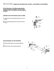
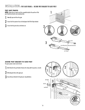
... her NNuut t ATTACH BRACKETS TO GATE OPERATOR 1 Attach post bracket assembly to operator using pins and hairpin clips. 2 Attach gate bracket to operator using pins and hairpin clips. 1 Pin Post Bracket Assembly Hairpin Clip Pin 2 Gate Bracket Hairpin Clip 13 INSTALLATION » ASSEMBLE GATE POST BRACKET (PULL-TO-OPEN) + ATTACH BRACKETS TO GATE OPERATOR All the illustrations on top...
... her NNuut t ATTACH BRACKETS TO GATE OPERATOR 1 Attach post bracket assembly to operator using pins and hairpin clips. 2 Attach gate bracket to operator using pins and hairpin clips. 1 Pin Post Bracket Assembly Hairpin Clip Pin 2 Gate Bracket Hairpin Clip 13 INSTALLATION » ASSEMBLE GATE POST BRACKET (PULL-TO-OPEN) + ATTACH BRACKETS TO GATE OPERATOR All the illustrations on top...
LA400 Manual
Page 16
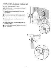
... open position (no greater than 100°) and hold operator against gate. 2 Place the operator arm against gate post at the desired position. INSTALLATION » POSITION GATE OPERATOR ON GATE POSITION GATE OPERATOR ON GATE NOTE: The post bracket assembly can be level. 2 3 Mark mounting holes on the gate post. Temporarily secure the gate bracket using a clamp. 4 Align the Pull-to-Open...
... open position (no greater than 100°) and hold operator against gate. 2 Place the operator arm against gate post at the desired position. INSTALLATION » POSITION GATE OPERATOR ON GATE POSITION GATE OPERATOR ON GATE NOTE: The post bracket assembly can be level. 2 3 Mark mounting holes on the gate post. Temporarily secure the gate bracket using a clamp. 4 Align the Pull-to-Open...
LA400 Manual
Page 17
... the post bracket to fully extend or fully retract. 1/2" (1.3 cm) SECURE POST BRACKET TO GATE POST The gate operator (arm) must be level. 1 Mark holes for the post bracket. INSTALLATION » TEST GATE TRAVEL + SECURE POST BRACKET TO GATE POST TEST GATE TRAVEL NOTE: If gate does not open and close completely adjust the position of the...
... the post bracket to fully extend or fully retract. 1/2" (1.3 cm) SECURE POST BRACKET TO GATE POST The gate operator (arm) must be level. 1 Mark holes for the post bracket. INSTALLATION » TEST GATE TRAVEL + SECURE POST BRACKET TO GATE POST TEST GATE TRAVEL NOTE: If gate does not open and close completely adjust the position of the...
LA400 Manual
Page 18
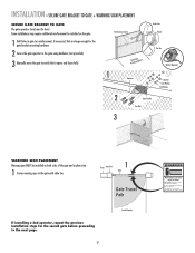
... large enough for vehicles only Pedestrians must be installed on both sides of the gate and in the gate area. Gate may require additional reinforcement be level. This entrance is for the gate bracket mounting hardware. 2 Secure the gate operator to the gate using hardware (not provided). 3 Manually move at any time without prior warning. INSTALLATION »...
... large enough for vehicles only Pedestrians must be installed on both sides of the gate and in the gate area. Gate may require additional reinforcement be level. This entrance is for the gate bracket mounting hardware. 2 Secure the gate operator to the gate using hardware (not provided). 3 Manually move at any time without prior warning. INSTALLATION »...

LA400 Manual
Page 19
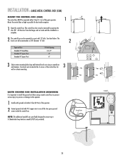
... Outs Knock Outs Knock Outs 7 A. Post B. INSTALLATION » STANDARD CONTROL BOX MOUNT THE CONTROL BOX The control box MUST be mounted within 5 feet (1.5 m) of the gate operator. Knock Outs B. Mount the control box as high as possible for best radio reception. 1 Remove screws and open the control box. 1 2 Disconnect the reset button...
... Outs Knock Outs Knock Outs 7 A. Post B. INSTALLATION » STANDARD CONTROL BOX MOUNT THE CONTROL BOX The control box MUST be mounted within 5 feet (1.5 m) of the gate operator. Knock Outs B. Mount the control box as high as possible for best radio reception. 1 Remove screws and open the control box. 1 2 Disconnect the reset button...
LA400 Manual
Page 21
... MOUNT THE CONTROL BOX (XLM) The control box MUST be mounted within 3 feet (0.9 m) of the operator. 2 Connect ground rod with 'U' bolts. Use knock outs located at the 4 corners of the gate operator. 1 90° Mount the control box as high as possible for 3 wall or column mounting. The ...control box door may be removed by opening the door 90°. NOTE: The additional standoffs are specifically designed to mount up to the operator. 1 Install earth...
... MOUNT THE CONTROL BOX (XLM) The control box MUST be mounted within 3 feet (0.9 m) of the operator. 2 Connect ground rod with 'U' bolts. Use knock outs located at the 4 corners of the gate operator. 1 90° Mount the control box as high as possible for 3 wall or column mounting. The ...control box door may be removed by opening the door 90°. NOTE: The additional standoffs are specifically designed to mount up to the operator. 1 Install earth...

LA400 Manual
Page 22
...be removed to power up additional gate operator accessories. ALARM LOCK SOL GND MAGR GATE 1 BR GR WH YL BL RD ACCESSORY POWER 12 V BR GR WH YL BL RD GATE 2 LEARN XMITTER ON OFF LOCK / BIPA RT DELAY CLOSE EDGE OPEN EDGE/ PHOTO OPEN PHOTO SET OPEN LIMIT GATE 1 CLOSE PHOTO SET CLOSE LIMIT... LEARN LIMITS FORCE GATE 2 ON OFF AUTO OPEN LOW BATT OFF MAX SINGLE BUTTON TIMER TO CLOSE OPEN CONTROL INPUTS SINGLE BUTTON RESET OFF MAX STOP CTRL PWR ...
...be removed to power up additional gate operator accessories. ALARM LOCK SOL GND MAGR GATE 1 BR GR WH YL BL RD ACCESSORY POWER 12 V BR GR WH YL BL RD GATE 2 LEARN XMITTER ON OFF LOCK / BIPA RT DELAY CLOSE EDGE OPEN EDGE/ PHOTO OPEN PHOTO SET OPEN LIMIT GATE 1 CLOSE PHOTO SET CLOSE LIMIT... LEARN LIMITS FORCE GATE 2 ON OFF AUTO OPEN LOW BATT OFF MAX SINGLE BUTTON TIMER TO CLOSE OPEN CONTROL INPUTS SINGLE BUTTON RESET OFF MAX STOP CTRL PWR ...
LA400 Manual
Page 23
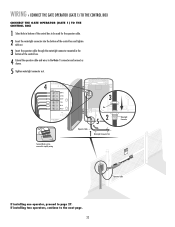
...216; GRN WHT YEL BLU RED Z12 ACCESSORY POWER GATE 1 BRN GRN WHT U4 YEL BLU RED 3 MAX C13 C4 F6 F2 FUSE OPEN Nut 52 Operator Cable 1 Watertight Connector Nut Terminal blocks can be used for the operator cable. 2 Insert the watertight connector into the ...connector mounted in bottom of the control box. 4 Extend the operator cable and wires to the Gate 1 connector and connect as shown. 5 Tighten watertight connector nut. WIRING » CONNECT THE GATE OPERATOR (GATE 1) TO THE CONTROL BOX CONNECT THE GATE OPERATOR (GATE 1) TO THE CONTROL BOX 1 Select hole in the bottom of...
...216; GRN WHT YEL BLU RED Z12 ACCESSORY POWER GATE 1 BRN GRN WHT U4 YEL BLU RED 3 MAX C13 C4 F6 F2 FUSE OPEN Nut 52 Operator Cable 1 Watertight Connector Nut Terminal blocks can be used for the operator cable. 2 Insert the watertight connector into the ...connector mounted in bottom of the control box. 4 Extend the operator cable and wires to the Gate 1 connector and connect as shown. 5 Tighten watertight connector nut. WIRING » CONNECT THE GATE OPERATOR (GATE 1) TO THE CONTROL BOX CONNECT THE GATE OPERATOR (GATE 1) TO THE CONTROL BOX 1 Select hole in the bottom of...

LA400 Manual
Page 25
... Box PTpDtKiMhlmeEoadiEyseneoPioeswnnttvCirtttliLiherhaIantEeonnncAusggcjhtRaumeiptl!GdeirursGriysaoeaaftrronteuteorwaoesmv.rapeereaChsnDryeiiacnaptmelgeean.oasrtahvottCeeehnaglaeytanutaternsayonerce Gate Operator (Gate 2) Gate Operator (Gate 1) 1 Junction Box Extension Cable PVC conduit at least 18" (45.7 cm) below ground level (grade) Terminal blocks can be used for the extension cable. WIRING » CONNECT THE GATE OPERATOR (GATE 2) TO THE CONTROL BOX (MODEL LA400-S ONLY) CONNECT THE GATE OPERATOR (GATE 2) TO THE CONTROL BOX (MODEL LA400-S ONLY) Before digging, contact...
... Box PTpDtKiMhlmeEoadiEyseneoPioeswnnttvCirtttliLiherhaIantEeonnncAusggcjhtRaumeiptl!GdeirursGriysaoeaaftrronteuteorwaoesmv.rapeereaChsnDryeiiacnaptmelgeean.oasrtahvottCeeehnaglaeytanutaternsayonerce Gate Operator (Gate 2) Gate Operator (Gate 1) 1 Junction Box Extension Cable PVC conduit at least 18" (45.7 cm) below ground level (grade) Terminal blocks can be used for the extension cable. WIRING » CONNECT THE GATE OPERATOR (GATE 2) TO THE CONTROL BOX (MODEL LA400-S ONLY) CONNECT THE GATE OPERATOR (GATE 2) TO THE CONTROL BOX (MODEL LA400-S ONLY) Before digging, contact...

LA400 Manual
Page 26
...through watertight connector nut and watertight connector. Drill two holes in the bottom of second operator. Screws (4) 5 Insert cables and watertight connectors into the holes in the bottom ...Box KKnoncokckOOutut JJuunncctitoionnBBooxx 5'W(1it.h5inm) Gate Operator (Gate 2) Junction Box Extension Cable ConCnoencnetcotorr Nut 6 Nut CCononnecntoer cNtuot r Nut Extension ExtCenasibonleCable 25 5 WirWeCotaintgenrhetictgtohrt Connector 4 WCoWCantoneierrntecitngothiregt chttor Operator OpCeraatbolreCable WIRING » JUNCTION BOX (MODEL LA400-S ONLY) JUNCTION BOX The following...
...through watertight connector nut and watertight connector. Drill two holes in the bottom of second operator. Screws (4) 5 Insert cables and watertight connectors into the holes in the bottom ...Box KKnoncokckOOutut JJuunncctitoionnBBooxx 5'W(1it.h5inm) Gate Operator (Gate 2) Junction Box Extension Cable ConCnoencnetcotorr Nut 6 Nut CCononnecntoer cNtuot r Nut Extension ExtCenasibonleCable 25 5 WirWeCotaintgenrhetictgtohrt Connector 4 WCoWCantoneierrntecitngothiregt chttor Operator OpCeraatbolreCable WIRING » JUNCTION BOX (MODEL LA400-S ONLY) JUNCTION BOX The following...

LA400 Manual
Page 45
REPAIR PARTS » CONTROL BOX + GATE OPERATOR ARM CONTROL BOX Refer to -Open bracket and hardware 44 44 If optional modifications and/or accessories are included with your operator, certain components may be added or removed from these lists. 88 22 77 33 44 66 11 55 ITEM PART...Includes 20 Amp (1), 15 Amp (2) Receiver Module - 390 MHz Receiver Module - 315 MHz Reset Switch (XLM Control Box) Alarm (XLM Control Box) GATE OPERATOR ARM 22 33 ITEM PART # DESCRIPTION QTY 1 41ASWG-442SA Release Lever 1 2 41ASWG-438SA Motor with Limit 1 11 Switch Harness 3 41ASWG-0014SA ...
REPAIR PARTS » CONTROL BOX + GATE OPERATOR ARM CONTROL BOX Refer to -Open bracket and hardware 44 44 If optional modifications and/or accessories are included with your operator, certain components may be added or removed from these lists. 88 22 77 33 44 66 11 55 ITEM PART...Includes 20 Amp (1), 15 Amp (2) Receiver Module - 390 MHz Receiver Module - 315 MHz Reset Switch (XLM Control Box) Alarm (XLM Control Box) GATE OPERATOR ARM 22 33 ITEM PART # DESCRIPTION QTY 1 41ASWG-442SA Release Lever 1 2 41ASWG-438SA Motor with Limit 1 11 Switch Harness 3 41ASWG-0014SA ...
LA400 Manual
Page 47
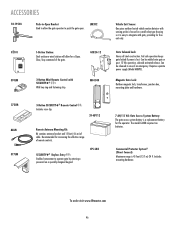
...29-NP712 Remote Antenna Mounting Kit: Kit contains antenna bracket and 15 feet (4.6 m) of cable. The model LA400 requires two batteries. Includes mounting hardware. SECURITY✚® Keyless Entry : Enables homeowner to operate gate by entering a password on a specially designed keypad. Commercial Protector System® (Direct Connect): Maximum range is...of an emergency. ACCESSORIES 50-19503 Push-to-Open Bracket Used toOPEN allow for increasing the effective range of remote controls. Gate Solenoid Lock: Heavy all steel construction. To order visit www.liftmaster.com 46
...29-NP712 Remote Antenna Mounting Kit: Kit contains antenna bracket and 15 feet (4.6 m) of cable. The model LA400 requires two batteries. Includes mounting hardware. SECURITY✚® Keyless Entry : Enables homeowner to operate gate by entering a password on a specially designed keypad. Commercial Protector System® (Direct Connect): Maximum range is...of an emergency. ACCESSORIES 50-19503 Push-to-Open Bracket Used toOPEN allow for increasing the effective range of remote controls. Gate Solenoid Lock: Heavy all steel construction. To order visit www.liftmaster.com 46


