
LA400 Manual
Page 1
LA400 & LA400-S MEDIUM DUTY SWING GATE OPERATOR OWNER'S MANUAL MeBtOoLaaxplrtC(giXooennLMatrl)ol Serial # Primary Arm Serial # Secondary Arm Serial # Control Box Installation Date The LA400 is intended for use with vehicular swing gates. The operator can be used in Class I, Class II and Class III applications. 2 YEAR WARRANTY Radio Receiver Built on Board 315 MHz
LA400 & LA400-S MEDIUM DUTY SWING GATE OPERATOR OWNER'S MANUAL MeBtOoLaaxplrtC(giXooennLMatrl)ol Serial # Primary Arm Serial # Secondary Arm Serial # Control Box Installation Date The LA400 is intended for use with vehicular swing gates. The operator can be used in Class I, Class II and Class III applications. 2 YEAR WARRANTY Radio Receiver Built on Board 315 MHz

LA400 Manual
Page 2
... Brackets to Gate Operator Determine Mounting Location Measuring and Marking for the Gate Bracket Position Gate Operator on Gate Test Gate Travel Secure Post Bracket to Gate Post Secure Gate Bracket to Gate Warning Sign Placement Standard Control Box Large Metal Control Box (XLM) WIRING Connect the Gate Operator (Gate 1) to the Control Box Set the Bipart Delay (Model LA400-S Only) Connect the Gate Operator (Gate 2) to...
... Brackets to Gate Operator Determine Mounting Location Measuring and Marking for the Gate Bracket Position Gate Operator on Gate Test Gate Travel Secure Post Bracket to Gate Post Secure Gate Bracket to Gate Warning Sign Placement Standard Control Box Large Metal Control Box (XLM) WIRING Connect the Gate Operator (Gate 1) to the Control Box Set the Bipart Delay (Model LA400-S Only) Connect the Gate Operator (Gate 2) to...

LA400 Manual
Page 4
... gate are not obstructed or impeded by a moving gate or barrier. 12. Reference owner's manual regarding placement of application. Care shall be located at least 6 feet (1.83 m) away from any point in a location so that enough clearance is supplied between the sensor and the gate operator ... contact sensors shall be properly installed and work freely in its arc of travel of the gate operator. 8. A gate operator can create risks for exposed rollers. 5. The operator is specifically designed for entrapment protection functions shall be located where the risk of entrapment or ...
... gate are not obstructed or impeded by a moving gate or barrier. 12. Reference owner's manual regarding placement of application. Care shall be located at least 6 feet (1.83 m) away from any point in a location so that enough clearance is supplied between the sensor and the gate operator ... contact sensors shall be properly installed and work freely in its arc of travel of the gate operator. 8. A gate operator can create risks for exposed rollers. 5. The operator is specifically designed for entrapment protection functions shall be located where the risk of entrapment or ...

LA400 Manual
Page 5
..., refer to ASTM F2200 for panel types. 1.5 An existing gate latch shall be disabled when a manually operated gate is retrofitted with a powered gate operator. 3.2 The following provisions shall apply to Class 1, Class II and Class III vehicular 2.3 Any existing automated gate, when the operator requires replacement, horizontal swing gates: shall be upgraded to conform to the provisions of this...
..., refer to ASTM F2200 for panel types. 1.5 An existing gate latch shall be disabled when a manually operated gate is retrofitted with a powered gate operator. 3.2 The following provisions shall apply to Class 1, Class II and Class III vehicular 2.3 Any existing automated gate, when the operator requires replacement, horizontal swing gates: shall be upgraded to conform to the provisions of this...
LA400 Manual
Page 7
.... NO ONE SHOULD CROSS THE PATH OF THE MOVING GATE. • Test the gate operator monthly. Read the ownerʼs manual. To reduce the risk of FIRE or INJURY to operator BEFORE proceeding. To avoid SERIOUS personal INJURY or DEATH from the gate. SAFETY » IMPORTANT SAFETY INFORMATION OPERATION AND MAINTENANCE • READ AND FOLLOW ALL INSTRUCTIONS...
.... NO ONE SHOULD CROSS THE PATH OF THE MOVING GATE. • Test the gate operator monthly. Read the ownerʼs manual. To reduce the risk of FIRE or INJURY to operator BEFORE proceeding. To avoid SERIOUS personal INJURY or DEATH from the gate. SAFETY » IMPORTANT SAFETY INFORMATION OPERATION AND MAINTENANCE • READ AND FOLLOW ALL INSTRUCTIONS...
LA400 Manual
Page 13
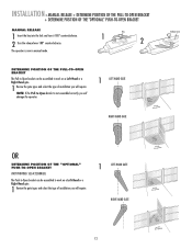
...will damage the operator. 1 LEFT-HAND GATE RIGHT-HAND GATE Release Lever OR DETERMINE POSITION OF THE "OPTIONAL" PUSH-TO-OPEN BRACKET (NOT PROVIDED. SEE ACCESSORIES) The Push-to-Open bracket can be assembled to work on a Left-Hand or a Right-Hand gate. 1 Review the gate types and .... NOTE: If the Pull-to work on a Left-Hand or a Right-Hand gate. 1 Review the gate types and select the type of installation you will require. 1 LEFT-HAND GATE RIGHT-HAND GATE 12 INSTALLATION » MANUAL RELEASE + DETERMINE POSITION OF THE PULL-TO-OPEN BRACKET + DETERMINE POSITION OF THE ...
...will damage the operator. 1 LEFT-HAND GATE RIGHT-HAND GATE Release Lever OR DETERMINE POSITION OF THE "OPTIONAL" PUSH-TO-OPEN BRACKET (NOT PROVIDED. SEE ACCESSORIES) The Push-to-Open bracket can be assembled to work on a Left-Hand or a Right-Hand gate. 1 Review the gate types and .... NOTE: If the Pull-to work on a Left-Hand or a Right-Hand gate. 1 Review the gate types and select the type of installation you will require. 1 LEFT-HAND GATE RIGHT-HAND GATE 12 INSTALLATION » MANUAL RELEASE + DETERMINE POSITION OF THE PULL-TO-OPEN BRACKET + DETERMINE POSITION OF THE ...
LA400 Manual
Page 15
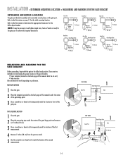
Gate Post Gate Hinge Point Gate Post Gate Hinge Point Gate Post Gate Hinge Point Operator Hinge Point 7" (18 cm) 7" (18 cm) Operator 7" (18 cm) Hinge Point 7" (18 cm) Operator 7" (18 cm) Hinge Point 7" (18 cm) Gate Post Gate Hinge Point Gate Post Gate Hinge Point Gate Post Gate Hinge Point 7" (18 cm) Operator Hinge Point 7" (18 cm) Operator 7" (18 cm) Hinge Point 7" (18 cm) Operator... the required dimensions. TEMPLATE METHOD 1 Close the gate. 2 Place the template (provided on the back page of this manual. Refer to the illustrations to determine the appropriate dimensions...
Gate Post Gate Hinge Point Gate Post Gate Hinge Point Gate Post Gate Hinge Point Operator Hinge Point 7" (18 cm) 7" (18 cm) Operator 7" (18 cm) Hinge Point 7" (18 cm) Operator 7" (18 cm) Hinge Point 7" (18 cm) Gate Post Gate Hinge Point Gate Post Gate Hinge Point Gate Post Gate Hinge Point 7" (18 cm) Operator Hinge Point 7" (18 cm) Operator 7" (18 cm) Hinge Point 7" (18 cm) Operator... the required dimensions. TEMPLATE METHOD 1 Close the gate. 2 Place the template (provided on the back page of this manual. Refer to the illustrations to determine the appropriate dimensions...
LA400 Manual
Page 17
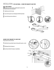
INSTALLATION » TEST GATE TRAVEL + SECURE POST BRACKET TO GATE POST TEST GATE TRAVEL NOTE: If gate does not open and close completely adjust the position of the 1 gate bracket and mark new mounting holes. 1 Manually open and close the gate. 2 Ensure that the operator does not bind against the Pull-to-Open bracket. 3 Ensure that the piston does...
INSTALLATION » TEST GATE TRAVEL + SECURE POST BRACKET TO GATE POST TEST GATE TRAVEL NOTE: If gate does not open and close completely adjust the position of the 1 gate bracket and mark new mounting holes. 1 Manually open and close the gate. 2 Ensure that the operator does not bind against the Pull-to-Open bracket. 3 Ensure that the piston does...
LA400 Manual
Page 18
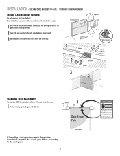
... KEEP CLEAR! Some installations may move the gate to verify that are large enough for the gate bracket mounting hardware. 2 Secure the gate operator to the gate using hardware (not provided). 3 Manually move at any time without prior warning. INSTALLATION » SECURE GATE BRACKET TO GATE + WARNING SIGN PLACEMENT SECURE GATE BRACKET TO GATE The gate operator (arm) must use separate entrance
... KEEP CLEAR! Some installations may move the gate to verify that are large enough for the gate bracket mounting hardware. 2 Secure the gate operator to the gate using hardware (not provided). 3 Manually move at any time without prior warning. INSTALLATION » SECURE GATE BRACKET TO GATE + WARNING SIGN PLACEMENT SECURE GATE BRACKET TO GATE The gate operator (arm) must use separate entrance
LA400 Manual
Page 40
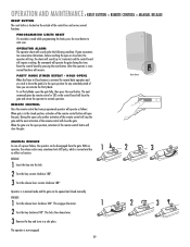
... for any extended period of the remote control will close the gate. RESET RESET Reset Button REMOTE CONTROL Once the remote control has been programmed operator will operate as follows: When gate is in the closed manually. MANUAL RELEASE In case of the control box and serves several functions....control or SBC on the control board will close limit, the operator will stop the gate and the next activation of time you wish to normal operation. When the gate is in manual mode and the gate can be disengaged from the gate. This engages the motor. 1 2 Turn the key clockwise ...
... for any extended period of the remote control will close the gate. RESET RESET Reset Button REMOTE CONTROL Once the remote control has been programmed operator will operate as follows: When gate is in the closed manually. MANUAL RELEASE In case of the control box and serves several functions....control or SBC on the control board will close limit, the operator will stop the gate and the next activation of time you wish to normal operation. When the gate is in manual mode and the gate can be disengaged from the gate. This engages the motor. 1 2 Turn the key clockwise ...
LA400 Manual
Page 41
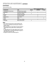
... suggested that the incoming voltage to adjust the gate force. DESCRIPTION External Entrapment Protection System Manual Release Gate Accessories Electrical Mounting Hardware Batteries Operator Warning Signs TASK Check and test for proper operation Check and test for proper operation Inspect for wear or damage Check all for proper operation Inspect all wire connections Check for tightness Replace...
... suggested that the incoming voltage to adjust the gate force. DESCRIPTION External Entrapment Protection System Manual Release Gate Accessories Electrical Mounting Hardware Batteries Operator Warning Signs TASK Check and test for proper operation Check and test for proper operation Inspect for wear or damage Check all for proper operation Inspect all wire connections Check for tightness Replace...

LA400 Pull to Open Addendum Manual
Page 1
... bracket assembly can be approximately 7" x 7". Typical 6" Post Hole Can also be used to mount operator if needed Addendum to 30-degrees of this hole helps add up to LA400 Owner's Manual Acceptable Configurations (will vary based on the gate post. Typical 4" Post Hole NOTE: The addition of movement in some applications. NOTE: This new...
... bracket assembly can be approximately 7" x 7". Typical 6" Post Hole Can also be used to mount operator if needed Addendum to 30-degrees of this hole helps add up to LA400 Owner's Manual Acceptable Configurations (will vary based on the gate post. Typical 4" Post Hole NOTE: The addition of movement in some applications. NOTE: This new...
LA400 Pull to Open Addendum Manual
Page 2
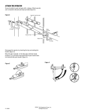
Attach operator arm to post and gate with c-clamps. Figure 2 Operator must be level C-Clamp Actuator Side Pin Gate Bracket Hairpin Clip C-Clamp Disengage the operator by inserting the key and rotating the handle (Figure 3). All Rights Reserved It is extremely important that the gate bracket does not bind with the post bracket (Figure 4). ATTACH THE OPERATOR Secure brackets to brackets with pins and clips provided (Figure 2). Move the gate manually to the fully open and fully closed positions. Figure 3 Figure 4 01-33464 ©2006, The Chamberlain Group, Inc.
Attach operator arm to post and gate with c-clamps. Figure 2 Operator must be level C-Clamp Actuator Side Pin Gate Bracket Hairpin Clip C-Clamp Disengage the operator by inserting the key and rotating the handle (Figure 3). All Rights Reserved It is extremely important that the gate bracket does not bind with the post bracket (Figure 4). ATTACH THE OPERATOR Secure brackets to brackets with pins and clips provided (Figure 2). Move the gate manually to the fully open and fully closed positions. Figure 3 Figure 4 01-33464 ©2006, The Chamberlain Group, Inc.


