

LA400 Manual
Page 2
...-Open) Attach Brackets to Gate Operator Determine Mounting Location Measuring and Marking for the Gate Bracket Position Gate Operator on Gate Test Gate Travel Secure Post Bracket to Gate Post Secure Gate Bracket to Gate Warning Sign Placement Standard Control Box Large Metal Control Box (XLM) WIRING Connect the Gate Operator (Gate 1) to the Control Box Set the Bipart Delay (Model LA400...
...-Open) Attach Brackets to Gate Operator Determine Mounting Location Measuring and Marking for the Gate Bracket Position Gate Operator on Gate Test Gate Travel Secure Post Bracket to Gate Post Secure Gate Bracket to Gate Warning Sign Placement Standard Control Box Large Metal Control Box (XLM) WIRING Connect the Gate Operator (Gate 1) to the Control Box Set the Bipart Delay (Model LA400...

LA400 Manual
Page 3
.../GENERAL ACCESS III VEHICULAR GATE OPERATOR A vehicular gate operator (or system) intended for each gate application. SAFETY ACCESSORY SELECTION All UL325 compliant LiftMaster gate operators will accept external entrapment protection devices to protect people from motorized gate systems. UL325 requires that... must be used for use on both the open and close directions of gate travel. Non-contact sensors such as gate edges. RESIDENTIAL VEHICULAR GATE OPERATOR I - SAFETY » UL325 MODEL CLASSIFICATIONS CLASS I A vehicular gate operator (or system) intended for use in ...
.../GENERAL ACCESS III VEHICULAR GATE OPERATOR A vehicular gate operator (or system) intended for each gate application. SAFETY ACCESSORY SELECTION All UL325 compliant LiftMaster gate operators will accept external entrapment protection devices to protect people from motorized gate systems. UL325 requires that... must be used for use on both the open and close directions of gate travel. Non-contact sensors such as gate edges. RESIDENTIAL VEHICULAR GATE OPERATOR I - SAFETY » UL325 MODEL CLASSIFICATIONS CLASS I A vehicular gate operator (or system) intended for use in ...

LA400 Manual
Page 4
... edge, trailing edge and post mounted both directions prior to mechanical damage. Swinging gates shall not open position. Outdoor or easily accessible controls shall have a security feature to potential hazards. 3. For a gate operator utilizing a non-contact sensor: a. c. b. A wireless contact sensor such... m) above the ground at the bottom edge of non-contact sensor for exposed rollers. 5. e. All openings of a horizontal slide gate are not obstructed or impeded by a moving part of the gate and where the user is greater than 6 inches (152 mm) above the ground to prevent a ...
... edge, trailing edge and post mounted both directions prior to mechanical damage. Swinging gates shall not open position. Outdoor or easily accessible controls shall have a security feature to potential hazards. 3. For a gate operator utilizing a non-contact sensor: a. c. b. A wireless contact sensor such... m) above the ground at the bottom edge of non-contact sensor for exposed rollers. 5. e. All openings of a horizontal slide gate are not obstructed or impeded by a moving part of the gate and where the user is greater than 6 inches (152 mm) above the ground to prevent a ...

LA400 Manual
Page 5
...as a wall, pillar or column, and a swing gate when in the open position or the 1.2 Gates shall be incorporated into a vehicular gate panel or function. supporting hardware. 3.1.4 Positive stops shall be initiated by a swing gate when in ASTM F2200. that the above grade and...shall apply to the application in either the fully open position shall not be less than 6 feet (1.83 m) 3.1.5 All gates shall be guarded or covered. VEHICULAR HORIZONTAL SLIDE GATES fixed object when the gate moves toward the fully open position. 4.1.1.2 Except for the zone specified in ...
...as a wall, pillar or column, and a swing gate when in the open position or the 1.2 Gates shall be incorporated into a vehicular gate panel or function. supporting hardware. 3.1.4 Positive stops shall be initiated by a swing gate when in ASTM F2200. that the above grade and...shall apply to the application in either the fully open position shall not be less than 6 feet (1.83 m) 3.1.5 All gates shall be guarded or covered. VEHICULAR HORIZONTAL SLIDE GATES fixed object when the gate moves toward the fully open position. 4.1.1.2 Except for the zone specified in ...

LA400 Manual
Page 6
ALWAYS wear protective gloves and eye protection when changing the battery or working around the battery compartment. • DO NOT use only LiftMaster part #K74-30762 for replacement batteries. Check with the control station installation. • ALL power wiring should be enclosed in a ...may come near the operator MUST NOT be sure to compensate for disposal instructions. To AVOID damaging plug-in BOTH the open and close gate. • NEVER use force adjustments to follow ALL specifications and warnings described below. To prevent SERIOUS INJURY or DEATH from a moving...
ALWAYS wear protective gloves and eye protection when changing the battery or working around the battery compartment. • DO NOT use only LiftMaster part #K74-30762 for replacement batteries. Check with the control station installation. • ALL power wiring should be enclosed in a ...may come near the operator MUST NOT be sure to compensate for disposal instructions. To AVOID damaging plug-in BOTH the open and close gate. • NEVER use force adjustments to follow ALL specifications and warnings described below. To prevent SERIOUS INJURY or DEATH from a moving...

LA400 Manual
Page 8
...37.4" (95 cm) 53.5" (136 cm) CARTON INVENTORY Carton inventory is doubled except for a 90° opening 4 Minutes -20° C to + 50° C -4° F to -Open Bracket (1) • Hex Bolt 5/16"-18 X 1-1/2" (5) • Square Neck Carriage Bolt 3/8"-16 X ...(2) 7 Six Conductor, 9 feet (2.7 m) • Warning Sign (2) • Battery (2) • Plug-in Transformer (1) LA400-S (SECOND GATE OPERATOR ARM) • Motor Cable - For Primary (Gate 1) and Secondary (Gate 2) installation the carton inventory is based on a Single Operator. Six Conductor, 40 feet (12.2 m) • Junction Box ...
...37.4" (95 cm) 53.5" (136 cm) CARTON INVENTORY Carton inventory is doubled except for a 90° opening 4 Minutes -20° C to + 50° C -4° F to -Open Bracket (1) • Hex Bolt 5/16"-18 X 1-1/2" (5) • Square Neck Carriage Bolt 3/8"-16 X ...(2) 7 Six Conductor, 9 feet (2.7 m) • Warning Sign (2) • Battery (2) • Plug-in Transformer (1) LA400-S (SECOND GATE OPERATOR ARM) • Motor Cable - For Primary (Gate 1) and Secondary (Gate 2) installation the carton inventory is based on a Single Operator. Six Conductor, 40 feet (12.2 m) • Junction Box ...

LA400 Manual
Page 10
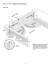
... Hinge Post Bracket Operator Operator Cable Antenna Control Box with Batteries Hinge Post Bracket Gate Bracket PVC Conduit (not provided) to protect the low voltage wire from lawn ..., such as when a vehicle trips the sensor while the gate is still moving. INSTALLATION » OVERVIEW OF TYPICAL INSTALLATION LEFT-HAND GATE Warning Sign Antenna Control Box with Batteries Photoelectric Sensors 12 Gauge...Installation (Optional) 12 Gauge Wire 8 feet (2.4 m) Photoelectric Sensors RIGHT-HAND GATE NOTE: One or more non-contact sensors shall be exercised to reduce the risk of entrapment or...
... Hinge Post Bracket Operator Operator Cable Antenna Control Box with Batteries Hinge Post Bracket Gate Bracket PVC Conduit (not provided) to protect the low voltage wire from lawn ..., such as when a vehicle trips the sensor while the gate is still moving. INSTALLATION » OVERVIEW OF TYPICAL INSTALLATION LEFT-HAND GATE Warning Sign Antenna Control Box with Batteries Photoelectric Sensors 12 Gauge...Installation (Optional) 12 Gauge Wire 8 feet (2.4 m) Photoelectric Sensors RIGHT-HAND GATE NOTE: One or more non-contact sensors shall be exercised to reduce the risk of entrapment or...
LA400 Manual
Page 11
Care shall be located where the risk of nuisance tripping, such as when a vehicle trips the sensor while the gate is still moving. 10 Photoelectric Sensors 12 Gauge Wire 8 feet (2.4 m) Earth Ground Installation (Optional) NOTE: One or more non-...low voltage wire from lawn mowers and string trimmers. INSTALLATION » OVERVIEW OF TYPICAL INSTALLATION DUAL GATE Warning Sign Hinge Antenna Post Bracket Gate Bracket Gate 1 Control Box with Batteries Operator Cable Gate 2 Junction Box Extension Cable Photoelectric Sensors PVC Conduit (not provided) to reduce the risk of ...
Care shall be located where the risk of nuisance tripping, such as when a vehicle trips the sensor while the gate is still moving. 10 Photoelectric Sensors 12 Gauge Wire 8 feet (2.4 m) Earth Ground Installation (Optional) NOTE: One or more non-...low voltage wire from lawn mowers and string trimmers. INSTALLATION » OVERVIEW OF TYPICAL INSTALLATION DUAL GATE Warning Sign Hinge Antenna Post Bracket Gate Bracket Gate 1 Control Box with Batteries Operator Cable Gate 2 Junction Box Extension Cable Photoelectric Sensors PVC Conduit (not provided) to reduce the risk of ...
LA400 Manual
Page 13
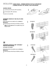
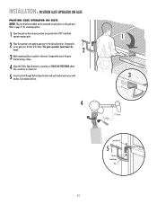
... on a Left-Hand or a Right-Hand gate. 1 Review the gate types and select the type of installation you will require. INSTALLATION » MANUAL RELEASE + DETERMINE POSITION OF THE PULL-TO-OPEN BRACKET + DETERMINE POSITION OF THE "OPTIONAL" PUSH-TO-OPEN BRACKET MANUAL RELEASE 1 Insert the key into...of installation you will damage the operator. 1 LEFT-HAND GATE RIGHT-HAND GATE Release Lever OR DETERMINE POSITION OF THE "OPTIONAL" PUSH-TO-OPEN BRACKET (NOT PROVIDED. SEE ACCESSORIES) The Push-to-Open bracket can be assembled to -Open bracket is now in manual mode. The operator is ...
... on a Left-Hand or a Right-Hand gate. 1 Review the gate types and select the type of installation you will require. INSTALLATION » MANUAL RELEASE + DETERMINE POSITION OF THE PULL-TO-OPEN BRACKET + DETERMINE POSITION OF THE "OPTIONAL" PUSH-TO-OPEN BRACKET MANUAL RELEASE 1 Insert the key into...of installation you will damage the operator. 1 LEFT-HAND GATE RIGHT-HAND GATE Release Lever OR DETERMINE POSITION OF THE "OPTIONAL" PUSH-TO-OPEN BRACKET (NOT PROVIDED. SEE ACCESSORIES) The Push-to-Open bracket can be assembled to -Open bracket is now in manual mode. The operator is ...
LA400 Manual
Page 14
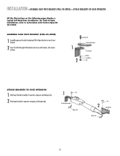
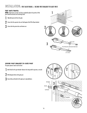
... bracket by placing Pull-to operator using pins and hairpin clips. 1 Pin Post Bracket Assembly Hairpin Clip Pin 2 Gate Bracket Hairpin Clip 13 For Push-to-Open installations refer to instructions with washer, lock washer and nut. 1 2 HeexxBBolot l3t/38/"8" Extension PBurlla-tcok-Oepten Bracket PPoostsBtrBacrkaectket WWaashsehrer LLoockckWaWshaesr her NNuut t ATTACH BRACKETS...
... bracket by placing Pull-to operator using pins and hairpin clips. 1 Pin Post Bracket Assembly Hairpin Clip Pin 2 Gate Bracket Hairpin Clip 13 For Push-to-Open installations refer to instructions with washer, lock washer and nut. 1 2 HeexxBBolot l3t/38/"8" Extension PBurlla-tcok-Oepten Bracket PPoostsBtrBacrkaectket WWaashsehrer LLoockckWaWshaesr her NNuut t ATTACH BRACKETS...
LA400 Manual
Page 15
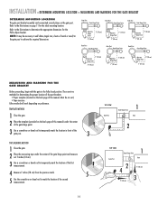
... Pull-to-Open bracket. There are two methods for determining the proper location of the post brackets: • Paper template (Located on the back page of this manual. Either method will work depending on the gate post. TEMPLATE METHOD 1 Close the gate. 2 Place...or dowel rod to mark the location of the second measurement. 14 TOP VIEW Gate Post Gate Hinge Point 1 Gate 2 TOP VIEW Gate Post Gate Hinge Point 1 Gate 2 4 7" (18 cm) 7" (18 cm) 3 Gate Post Gate Hinge Point Gate Post Gate Hinge Point Gate Post Gate Hinge Point Operator Hinge Point 7" (18 cm) 7" (18 cm) Operator...
... Pull-to-Open bracket. There are two methods for determining the proper location of the post brackets: • Paper template (Located on the back page of this manual. Either method will work depending on the gate post. TEMPLATE METHOD 1 Close the gate. 2 Place...or dowel rod to mark the location of the second measurement. 14 TOP VIEW Gate Post Gate Hinge Point 1 Gate 2 TOP VIEW Gate Post Gate Hinge Point 1 Gate 2 4 7" (18 cm) 7" (18 cm) 3 Gate Post Gate Hinge Point Gate Post Gate Hinge Point Gate Post Gate Hinge Point Operator Hinge Point 7" (18 cm) 7" (18 cm) Operator...
LA400 Manual
Page 16
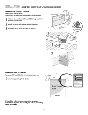
... GATE OPERATOR ON GATE POSITION GATE OPERATOR ON GATE NOTE: The post bracket assembly can be level. 2 3 Mark mounting holes on the gate post. Refer to page 11 for reference. The gate operator (arm) must be mounted several places on gate for mounting options. 1 Open the gate to -Open bracket...screwdriver or dowel rod. 5 Insert hex bolt through Pull-to desired open position (no greater than 100°) and hold operator against gate. 2 Place the operator arm against gate post at the desired position. Temporarily secure gate post bracket with washer, lock washer and nut. 1 3 4 7"...
... GATE OPERATOR ON GATE POSITION GATE OPERATOR ON GATE NOTE: The post bracket assembly can be level. 2 3 Mark mounting holes on the gate post. Refer to page 11 for reference. The gate operator (arm) must be mounted several places on gate for mounting options. 1 Open the gate to -Open bracket...screwdriver or dowel rod. 5 Insert hex bolt through Pull-to desired open position (no greater than 100°) and hold operator against gate. 2 Place the operator arm against gate post at the desired position. Temporarily secure gate post bracket with washer, lock washer and nut. 1 3 4 7"...
LA400 Manual
Page 17
INSTALLATION » TEST GATE TRAVEL + SECURE POST BRACKET TO GATE POST TEST GATE TRAVEL NOTE: If gate does not open and close completely adjust the position of the 1 gate bracket and mark new mounting holes. 1 Manually open and close the gate. 2 Ensure that the operator does not bind against the Pull-to-Open bracket. 3 Ensure that the piston does not...
INSTALLATION » TEST GATE TRAVEL + SECURE POST BRACKET TO GATE POST TEST GATE TRAVEL NOTE: If gate does not open and close completely adjust the position of the 1 gate bracket and mark new mounting holes. 1 Manually open and close the gate. 2 Ensure that the operator does not bind against the Pull-to-Open bracket. 3 Ensure that the piston does not...
LA400 Manual
Page 18
... vehicles only Pedestrians must be installed on the gate. 1 Drill holes in gate (or reinforcement, if necessary) that it opens and closes fully. Do not let children operate the gate or play in the gate area. INSTALLATION » SECURE GATE BRACKET TO GATE + WARNING SIGN PLACEMENT SECURE GATE BRACKET TO GATE The gate operator (arm) must use separate entrance Some...
... vehicles only Pedestrians must be installed on the gate. 1 Drill holes in gate (or reinforcement, if necessary) that it opens and closes fully. Do not let children operate the gate or play in the gate area. INSTALLATION » SECURE GATE BRACKET TO GATE + WARNING SIGN PLACEMENT SECURE GATE BRACKET TO GATE The gate operator (arm) must use separate entrance Some...

LA400 Manual
Page 19
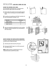
... Connector 4 3 2 Reset Button Connections Knock Outs Knock Outs Knock Outs 7 A. Mount the control box as high as possible for best radio reception. 1 Remove screws and open the control box. 1 2 Disconnect the reset button, alarm, and coaxial connector. 3 Loosen screws to remove the control board and mounting bracket. 4 Remove the control board... the appropriate hardware (not provided). C. 18 INSTALLATION » STANDARD CONTROL BOX MOUNT THE CONTROL BOX The control box MUST be mounted within 5 feet (1.5 m) of the gate operator. Knock Outs B. A.
... Connector 4 3 2 Reset Button Connections Knock Outs Knock Outs Knock Outs 7 A. Mount the control box as high as possible for best radio reception. 1 Remove screws and open the control box. 1 2 Disconnect the reset button, alarm, and coaxial connector. 3 Loosen screws to remove the control board and mounting bracket. 4 Remove the control board... the appropriate hardware (not provided). C. 18 INSTALLATION » STANDARD CONTROL BOX MOUNT THE CONTROL BOX The control box MUST be mounted within 5 feet (1.5 m) of the gate operator. Knock Outs B. A.
LA400 Manual
Page 21
... OFF MAX LEARN XMITTER ON OFF LOCK / BIPA RT DELAY CLOSE EDGE SET OPEN LIMIT OPEN EDGE/ PHOTO GATE 1 SET CLOSE LIMIT LEARN LIMITS OPEN PHOTO GATE 2 FORCE ON OFF CLOSE PHOTO AUTO OPEN LOW BATT OFF MAX SINGLE BUTTON TIMER TO CLOSE OPEN CONTROL INPUTS SINGLE BUTTON OFF MAX RESET STOP CTRL PWR CTRL PWR SHADOW...
... OFF MAX LEARN XMITTER ON OFF LOCK / BIPA RT DELAY CLOSE EDGE SET OPEN LIMIT OPEN EDGE/ PHOTO GATE 1 SET CLOSE LIMIT LEARN LIMITS OPEN PHOTO GATE 2 FORCE ON OFF CLOSE PHOTO AUTO OPEN LOW BATT OFF MAX SINGLE BUTTON TIMER TO CLOSE OPEN CONTROL INPUTS SINGLE BUTTON OFF MAX RESET STOP CTRL PWR CTRL PWR SHADOW...

LA400 Manual
Page 22
...SOL GND MAGR GATE 1 BR GR WH YL BL RD ACCESSORY POWER 12 V BR GR WH YL BL RD GATE 2 LEARN XMITTER ON OFF LOCK / BIPA RT DELAY CLOSE EDGE OPEN EDGE/ PHOTO OPEN PHOTO SET OPEN LIMIT GATE 1 CLOSE PHOTO SET CLOSE LIMIT LEARN LIMITS FORCE GATE 2 ON OFF AUTO OPEN LOW BATT OFF... MAX SINGLE BUTTON TIMER TO CLOSE OPEN CONTROL INPUTS SINGLE BUTTON RESET OFF MAX...
...SOL GND MAGR GATE 1 BR GR WH YL BL RD ACCESSORY POWER 12 V BR GR WH YL BL RD GATE 2 LEARN XMITTER ON OFF LOCK / BIPA RT DELAY CLOSE EDGE OPEN EDGE/ PHOTO OPEN PHOTO SET OPEN LIMIT GATE 1 CLOSE PHOTO SET CLOSE LIMIT LEARN LIMITS FORCE GATE 2 ON OFF AUTO OPEN LOW BATT OFF... MAX SINGLE BUTTON TIMER TO CLOSE OPEN CONTROL INPUTS SINGLE BUTTON RESET OFF MAX...

LA400 Manual
Page 44
...Obstructed Arm (bottoms out). 2) Bad RPM Sensor. 3) Too much mA pulled off board. GATE'S DO NOT OPEN/ CLOSE IN SYNC GATE DOES NOT AUTOMATICALLY CLOSE Auto Close Timer not closing gate. 1) Low battery. 2) Gate met an obstruction. 1) Constant Open Command (Check LED's). 2) Timer-to-Close not set. 3) Accessory device wired to -Close ... batteries. See Installation section of wires. MOTOR DOES NOT RUN Relays "click" when radio or SBC signal is not bottomed out. GATE OPENS BUT DOES NOT CLOSE Audible beeps (3 times) when command is given. See Programming Remote instructions. Clear all...
...Obstructed Arm (bottoms out). 2) Bad RPM Sensor. 3) Too much mA pulled off board. GATE'S DO NOT OPEN/ CLOSE IN SYNC GATE DOES NOT AUTOMATICALLY CLOSE Auto Close Timer not closing gate. 1) Low battery. 2) Gate met an obstruction. 1) Constant Open Command (Check LED's). 2) Timer-to-Close not set. 3) Accessory device wired to -Close ... batteries. See Installation section of wires. MOTOR DOES NOT RUN Relays "click" when radio or SBC signal is not bottomed out. GATE OPENS BUT DOES NOT CLOSE Audible beeps (3 times) when command is given. See Programming Remote instructions. Clear all...
LA400 Manual
Page 47
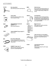
...To order visit www.liftmaster.com 46 Magnetic Gate Lock: Outdoor magnetic...Open Bracket Used toOPEN allow for a Open, Close, Stop command of the gate...OPEN LM202 02101 OPEN OPEN OPEN 370LM 1-Button Station: Steel enclosure wired station will allow the gate operator to operate gate by entering a password on a specially designed keypad. SECURITY✚® Keyless Entry : Enables homeowner to push the gate open. GC824-12 3-Button Mini-Remote Control with gate..., providing for free exit only. Fail safe operation keeps gate...
...To order visit www.liftmaster.com 46 Magnetic Gate Lock: Outdoor magnetic...Open Bracket Used toOPEN allow for a Open, Close, Stop command of the gate...OPEN LM202 02101 OPEN OPEN OPEN 370LM 1-Button Station: Steel enclosure wired station will allow the gate operator to operate gate by entering a password on a specially designed keypad. SECURITY✚® Keyless Entry : Enables homeowner to push the gate open. GC824-12 3-Button Mini-Remote Control with gate..., providing for free exit only. Fail safe operation keeps gate...
LA400 Push to Open Addendum Manual
Page 2
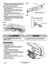
... 10. Once brackets are clamped in place, remove clevis pins and washers to mark holes in Open Position LEVEL Horizontal Cross Member Mark cross member through middle of gate bracket slots and drill 11/32" holes Mark fence post through middle of FIRE or INJURY to... and cross member. 11. Replace both batteries. 6. Reconnect power to the positive (+) terminals (red). With gate open and operator in use ONLY Chamberlain part #K74-30762 for gate bracket. 12. Remove control board and mounting plate. 5. Secure post bracket assembly to cross member with 3/8"-16 x 6" ...
... 10. Once brackets are clamped in place, remove clevis pins and washers to mark holes in Open Position LEVEL Horizontal Cross Member Mark cross member through middle of gate bracket slots and drill 11/32" holes Mark fence post through middle of FIRE or INJURY to... and cross member. 11. Replace both batteries. 6. Reconnect power to the positive (+) terminals (red). With gate open and operator in use ONLY Chamberlain part #K74-30762 for gate bracket. 12. Remove control board and mounting plate. 5. Secure post bracket assembly to cross member with 3/8"-16 x 6" ...


