

LA400 Manual
Page 2
...Open) Attach Brackets to Gate Operator Determine Mounting Location Measuring and Marking for the Gate Bracket Position Gate Operator on Gate Test Gate Travel Secure Post Bracket to Gate Post Secure Gate Bracket to Gate Warning Sign Placement Standard Control Box Large Metal Control Box (XLM) WIRING Connect the Gate Operator (Gate 1) to the Control Box Set the Bipart Delay (Model LA400... Button Remote Control Manual Release Maintenance TROUBLESHOOTING Basic Control Board Layout Wiring Diagram Diagnostic Codes Troubleshooting Chart REPAIR PARTS Control Box Gate Operator Arm How to Order Repair ...
...Open) Attach Brackets to Gate Operator Determine Mounting Location Measuring and Marking for the Gate Bracket Position Gate Operator on Gate Test Gate Travel Secure Post Bracket to Gate Post Secure Gate Bracket to Gate Warning Sign Placement Standard Control Box Large Metal Control Box (XLM) WIRING Connect the Gate Operator (Gate 1) to the Control Box Set the Bipart Delay (Model LA400... Button Remote Control Manual Release Maintenance TROUBLESHOOTING Basic Control Board Layout Wiring Diagram Diagnostic Codes Troubleshooting Chart REPAIR PARTS Control Box Gate Operator Arm How to Order Repair ...
LA400 Manual
Page 31
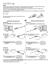
...RESET BUTTON 4 Press the Gate 1 right button to move gate to the desired OPEN position. Control SET OPEN SET CLOSE board will blink). DIAGNOSTIC GATE 1 SET CLOSE 7 When gate is mounted and how many operators the installation includes. If the problem continues, see Troubleshooting section.) Test the limits ...by turning the release lever clockwise 180°, then turning the key clockwise 180°. The programming times-out automatically after 60 seconds of the gate the control box is in the desired...
...RESET BUTTON 4 Press the Gate 1 right button to move gate to the desired OPEN position. Control SET OPEN SET CLOSE board will blink). DIAGNOSTIC GATE 1 SET CLOSE 7 When gate is mounted and how many operators the installation includes. If the problem continues, see Troubleshooting section.) Test the limits ...by turning the release lever clockwise 180°, then turning the key clockwise 180°. The programming times-out automatically after 60 seconds of the gate the control box is in the desired...
LA400 Manual
Page 32
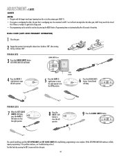
... CLOSE LIMIT FORCE PROGRAM CLOSE 7 When the SET CLOSE LIMITS LED blinks, press the GATE 2 left operator. DIAGNOSTIC GATE 1 SET CLOSE 5 Press the GATE 2 right button to open the left operator. If the problem continues, see Troubleshooting section.) Test the limits by turning the release lever clockwise 180°, then turning the key clockwise 180...
... CLOSE LIMIT FORCE PROGRAM CLOSE 7 When the SET CLOSE LIMITS LED blinks, press the GATE 2 left operator. DIAGNOSTIC GATE 1 SET CLOSE 5 Press the GATE 2 right button to open the left operator. If the problem continues, see Troubleshooting section.) Test the limits by turning the release lever clockwise 180°, then turning the key clockwise 180...

LA400 Manual
Page 33
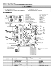
...complete. (If the SET OPEN LIMIT LED continues to be closed first if there is overlap or a gate lock is being used. • The programming can be exited at any time by pressing the RESET button. If the problem continues, see Troubleshooting section.) Test the limits ...by turning the release lever clockwise 180°, then turning the key clockwise 180°. Control LIMIT LIMIT FORCE board will blink). DIAGNOSTIC 9 Press the LEARN LIMITS SET GATE 1 button. SET CLOSE LIMIT LE LIMITS 6 Press the LEARN LIMITS SET SET GATE 2 OPEN...
...complete. (If the SET OPEN LIMIT LED continues to be closed first if there is overlap or a gate lock is being used. • The programming can be exited at any time by pressing the RESET button. If the problem continues, see Troubleshooting section.) Test the limits ...by turning the release lever clockwise 180°, then turning the key clockwise 180°. Control LIMIT LIMIT FORCE board will blink). DIAGNOSTIC 9 Press the LEARN LIMITS SET GATE 1 button. SET CLOSE LIMIT LE LIMITS 6 Press the LEARN LIMITS SET SET GATE 2 OPEN...

LA400 Manual
Page 42
... Button Force Bipart Delay Timer-to-Close Receiver P1 D6 O1 2 3 4 5 N TROUBLESHOOTING » BASIC CONTROL BOARD LAYOUT BASIC CONTROL BOARD LAYOUT 20 19 17 26 1 14 13 18 12 11* 10 21 P2 R223 ALARM NO C MAGLOCK NO C NC Z1 GATE 1 BRN GRN WHT YEL BLU RED 10A 32V D1Ø Z12... L1 1 S8 R2 OFF OFF ON SAVE ON MAGLOCK LEARN R1 XMITTER SINGLE NO DUAL MODE NC EDGE 2 F3 NO NC PHOTO S1 K2 DIAGNOSTIC GATE 1 K1 Q9 SET OPEN LIMIT SET CLOSE LIMIT LEARN LIMITS R2Ø7 Z2Ø R227 J18 R224 U4 Z22 R92 R91 R94 R93 CLOSE EDGE...
... Button Force Bipart Delay Timer-to-Close Receiver P1 D6 O1 2 3 4 5 N TROUBLESHOOTING » BASIC CONTROL BOARD LAYOUT BASIC CONTROL BOARD LAYOUT 20 19 17 26 1 14 13 18 12 11* 10 21 P2 R223 ALARM NO C MAGLOCK NO C NC Z1 GATE 1 BRN GRN WHT YEL BLU RED 10A 32V D1Ø Z12... L1 1 S8 R2 OFF OFF ON SAVE ON MAGLOCK LEARN R1 XMITTER SINGLE NO DUAL MODE NC EDGE 2 F3 NO NC PHOTO S1 K2 DIAGNOSTIC GATE 1 K1 Q9 SET OPEN LIMIT SET CLOSE LIMIT LEARN LIMITS R2Ø7 Z2Ø R227 J18 R224 U4 Z22 R92 R91 R94 R93 CLOSE EDGE...
LA400 Manual
Page 43
.... Reset Limits CLOSE PHOTO EYE 6. 24VDC ACCESSORY OUTPUT 7. MAGLOCK/SOLENOID OUTPUT 14. SECOND GATE JOG 22. OPERATOR ARM CONNECTION 11. 24VDC ACCESSORY OUTPUT 12. BATTERY INPUT #2 17. LIMIT SET 21. TROUBLESHOOTING » WIRING DIAGRAM + DIAGNOSTIC CODES To protect against fire: • Replace ONLY with...EDGE CPS-LN4 OR EDGE 4 PHOTO OR PHOTO CPS-LN4 OR 5 CPS-LN4 OR OR PHOTO PHOTO 6 24VDC OUTPUT SWITCHED OFF IN LOW POWER MODE OPEN (EXIT LOOP) SINGLE BUTTON RESET S T O P COMMON (+24VDC) COMMON (+24VDC) 7 SHADOW LOOP INTERRUPT LOOP COMMON (+24VDC) 8 NOTE: Yellow/...
.... Reset Limits CLOSE PHOTO EYE 6. 24VDC ACCESSORY OUTPUT 7. MAGLOCK/SOLENOID OUTPUT 14. SECOND GATE JOG 22. OPERATOR ARM CONNECTION 11. 24VDC ACCESSORY OUTPUT 12. BATTERY INPUT #2 17. LIMIT SET 21. TROUBLESHOOTING » WIRING DIAGRAM + DIAGNOSTIC CODES To protect against fire: • Replace ONLY with...EDGE CPS-LN4 OR EDGE 4 PHOTO OR PHOTO CPS-LN4 OR 5 CPS-LN4 OR OR PHOTO PHOTO 6 24VDC OUTPUT SWITCHED OFF IN LOW POWER MODE OPEN (EXIT LOOP) SINGLE BUTTON RESET S T O P COMMON (+24VDC) COMMON (+24VDC) 7 SHADOW LOOP INTERRUPT LOOP COMMON (+24VDC) 8 NOTE: Yellow/...

LA400 Manual
Page 44
... operation. GATE OPENS BUT DOES NOT CLOSE Audible beeps (3 times) when command is given, but the operator does not move. Voltage must be connected. Replace motor. Clear gate from obstruction. Voltage must be >23 V at battery connection. See Bipart Delay section for proper installation of accessory. Replace accessory device. 43 TROUBLESHOOTING » TROUBLESHOOTING CHART FAULT...
... operation. GATE OPENS BUT DOES NOT CLOSE Audible beeps (3 times) when command is given, but the operator does not move. Voltage must be connected. Replace motor. Clear gate from obstruction. Voltage must be >23 V at battery connection. See Bipart Delay section for proper installation of accessory. Replace accessory device. 43 TROUBLESHOOTING » TROUBLESHOOTING CHART FAULT...


