

LA400 Manual
Page 2
...Open) Attach Brackets to Gate Operator Determine Mounting Location Measuring and Marking for the Gate Bracket Position Gate Operator on Gate Test Gate Travel Secure Post Bracket to Gate Post Secure Gate Bracket to Gate Warning Sign Placement Standard Control Box Large Metal Control Box (XLM) WIRING Connect the Gate Operator (Gate 1) to the Control Box Set the Bipart Delay (Model LA400...Control Board Layout Wiring Diagram Diagnostic Codes Troubleshooting Chart REPAIR PARTS Control Box Gate Operator Arm How to Order Repair Parts WARRANTY POLICY ACCESSORIES TEMPLATE SAFETY » SAFETY SYMBOL AND...
...Open) Attach Brackets to Gate Operator Determine Mounting Location Measuring and Marking for the Gate Bracket Position Gate Operator on Gate Test Gate Travel Secure Post Bracket to Gate Post Secure Gate Bracket to Gate Warning Sign Placement Standard Control Box Large Metal Control Box (XLM) WIRING Connect the Gate Operator (Gate 1) to the Control Box Set the Bipart Delay (Model LA400...Control Board Layout Wiring Diagram Diagnostic Codes Troubleshooting Chart REPAIR PARTS Control Box Gate Operator Arm How to Order Repair Parts WARRANTY POLICY ACCESSORIES TEMPLATE SAFETY » SAFETY SYMBOL AND...

LA400 Manual
Page 4
... must be located in its wiring arranged so the communication between the gate and adjacent structures when opening and closing to the installation of the gate operator. 8. Controls intended for the construction and the usage class of many component parts. b. The pedestrian access opening . Gate systems are eliminated or guarded, and guarding is appropriate for user...
... must be located in its wiring arranged so the communication between the gate and adjacent structures when opening and closing to the installation of the gate operator. 8. Controls intended for the construction and the usage class of many component parts. b. The pedestrian access opening . Gate systems are eliminated or guarded, and guarding is appropriate for user...

LA400 Manual
Page 6
... reduce the risk of SEVERE INJURY or DEATH: • ANY maintenance to the operator or in BOTH the open and close gate. • NEVER use only LiftMaster part #K74-30762 for a binding or sticking gate. • If one or more non-contact sensors shall be located where the risk of the... gate in PLAIN VIEW. • Permanently secure each warning sign in separate conduit. • BEFORE installing power wiring or control stations ...
... reduce the risk of SEVERE INJURY or DEATH: • ANY maintenance to the operator or in BOTH the open and close gate. • NEVER use only LiftMaster part #K74-30762 for a binding or sticking gate. • If one or more non-contact sensors shall be located where the risk of the... gate in PLAIN VIEW. • Permanently secure each warning sign in separate conduit. • BEFORE installing power wiring or control stations ...

LA400 Manual
Page 24
...the control box be set as this gate. BIPART DELAY BI-PART DELAY Z9 Z8 OFF MAX OUTSIDE PROPERTY Primary Gate - WIRING » SET THE BIPART DELAY (MODEL LA400-S ONLY) SET THE BIPART DELAY (MODEL LA400-S ONLY) In some dual gate installations, one gate or if using a solenoid lock,... closest to the control box to the Gate 2 connector and 1 the operator on the control board. Primary Gate OUTSIDE PROPERTY 23 If there is 0 to desired setting. Connect to Gate 1 Connector on a gate, the gate with the lock attached to open first and close second. If a solenoid...
...the control box be set as this gate. BIPART DELAY BI-PART DELAY Z9 Z8 OFF MAX OUTSIDE PROPERTY Primary Gate - WIRING » SET THE BIPART DELAY (MODEL LA400-S ONLY) SET THE BIPART DELAY (MODEL LA400-S ONLY) In some dual gate installations, one gate or if using a solenoid lock,... closest to the control box to the Gate 2 connector and 1 the operator on the control board. Primary Gate OUTSIDE PROPERTY 23 If there is 0 to desired setting. Connect to Gate 1 Connector on a gate, the gate with the lock attached to open first and close second. If a solenoid...
LA400 Manual
Page 35
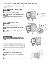
...LEARN XMITTER button and release (LED will activate twice. THERE ARE NO OTHER USER SERVICEABLE PARTS. Operation is stopping at the OPEN and CLOSE limits. 3 Test the force by making sure the gate will stop and reverse on contact with FCC Standards FOR HOME OR OFFICE USE. For ... (2) this receiver and/or transmitter are made, test the operator: 1 Use the Single Button Control (SBC) button to open and close the gate. 2 Test the limits by making sure the gate is subject to Accessories. PROGRAMMING » REMOTE CONTROLS + KEYLESS ENTRY + ERASE ALL CODES + TEST A combined total of...
...LEARN XMITTER button and release (LED will activate twice. THERE ARE NO OTHER USER SERVICEABLE PARTS. Operation is stopping at the OPEN and CLOSE limits. 3 Test the force by making sure the gate will stop and reverse on contact with FCC Standards FOR HOME OR OFFICE USE. For ... (2) this receiver and/or transmitter are made, test the operator: 1 Use the Single Button Control (SBC) button to open and close the gate. 2 Test the limits by making sure the gate is subject to Accessories. PROGRAMMING » REMOTE CONTROLS + KEYLESS ENTRY + ERASE ALL CODES + TEST A combined total of...

LA400 Manual
Page 38
... will have no effect. Latching this input will reverse an opening will reverse a closing gate to Terminal P8 while the gate is active. OPEN SAFETY PHOTOELECTRIC SENSOR (ENTRAPMENT) This input will pause an opening gate until the obstruction has been removed. TERMINAL P7 - SHADOW ... with an Open Edge device or a Retro-Reflective Photoelectric Sensor connected to the open . Order part number LA400-BOX to -Close if that feature has been enabled. NOTE: Shadow loop is disabled when gate is closing gate. Activating this input will pause an opening gate until the ...
... will have no effect. Latching this input will reverse an opening will reverse a closing gate to Terminal P8 while the gate is active. OPEN SAFETY PHOTOELECTRIC SENSOR (ENTRAPMENT) This input will pause an opening gate until the obstruction has been removed. TERMINAL P7 - SHADOW ... with an Open Edge device or a Retro-Reflective Photoelectric Sensor connected to the open . Order part number LA400-BOX to -Close if that feature has been enabled. NOTE: Shadow loop is disabled when gate is closing gate. Activating this input will pause an opening gate until the ...

LA400 Manual
Page 45
REPAIR PARTS » CONTROL BOX + GATE OPERATOR ARM CONTROL BOX Refer to -Open bracket and hardware 44 44 If optional modifications and/or accessories are included with your operator, certain components may be added or removed from these lists. 88 22 77 33 44 66 11 55 ITEM PART #... 15 Amp (2) Receiver Module - 390 MHz Receiver Module - 315 MHz Reset Switch (XLM Control Box) Alarm (XLM Control Box) GATE OPERATOR ARM 22 33 ITEM PART # DESCRIPTION QTY 1 41ASWG-442SA Release Lever 1 2 41ASWG-438SA Motor with Limit 1 11 Switch Harness 3 41ASWG-0014SA Rear Connector ...
REPAIR PARTS » CONTROL BOX + GATE OPERATOR ARM CONTROL BOX Refer to -Open bracket and hardware 44 44 If optional modifications and/or accessories are included with your operator, certain components may be added or removed from these lists. 88 22 77 33 44 66 11 55 ITEM PART #... 15 Amp (2) Receiver Module - 390 MHz Receiver Module - 315 MHz Reset Switch (XLM Control Box) Alarm (XLM Control Box) GATE OPERATOR ARM 22 33 ITEM PART # DESCRIPTION QTY 1 41ASWG-442SA Release Lever 1 2 41ASWG-438SA Motor with Limit 1 11 Switch Harness 3 41ASWG-0014SA Rear Connector ...
LA400 Push to Open Addendum Manual
Page 2
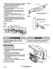
...quick connect terminals to operator BEFORE proceeding. Disconnect terminals leads to both batteries and connect red wires to the positive (+) terminals (red). With gate open and operator in place, remove clevis pins and washers to persons use to cross member, using C clamp. Once brackets are clamped in retracted... position, clamp bracket to the control board. Be sure to mark holes in use ONLY Chamberlain part #K74-30762 for bolt holes on fence posts and cross member. Drill 13/32" holes in place at this time (Figures 4 & 6)....
...quick connect terminals to operator BEFORE proceeding. Disconnect terminals leads to both batteries and connect red wires to the positive (+) terminals (red). With gate open and operator in place, remove clevis pins and washers to persons use to cross member, using C clamp. Once brackets are clamped in retracted... position, clamp bracket to the control board. Be sure to mark holes in use ONLY Chamberlain part #K74-30762 for bolt holes on fence posts and cross member. Drill 13/32" holes in place at this time (Figures 4 & 6)....


