

LA400 Manual
Page 2
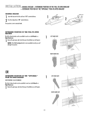
... Your Gate Mounting Options Manual Release Determine Position of the Pull-to-Open Bracket Determine Position of the "Optional" Push-to-Open Bracket Assemble Gate Post Bracket (Pull-to-Open) Attach Brackets to Gate Operator Determine Mounting Location Measuring and Marking for the Gate Bracket Position Gate Operator on Gate Test Gate Travel Secure Post Bracket to Gate Post Secure Gate Bracket to Gate...
... Your Gate Mounting Options Manual Release Determine Position of the Pull-to-Open Bracket Determine Position of the "Optional" Push-to-Open Bracket Assemble Gate Post Bracket (Pull-to-Open) Attach Brackets to Gate Operator Determine Mounting Location Measuring and Marking for the Gate Bracket Position Gate Operator on Gate Test Gate Travel Secure Post Bracket to Gate Post Secure Gate Bracket to Gate...

LA400 Manual
Page 4
... of the adjacent fence that persons will not come in the lineof-sight of the vehicular gate. 6. Install the gate operator only when: a. All openings of a horizontal slide gate are eliminated or guarded, and guarding is only one on the inside and outside leading edge... of many component parts. c. Activation of application. Reference owner's manual regarding placement of non-contact sensor for each individual application. ...
... of the adjacent fence that persons will not come in the lineof-sight of the vehicular gate. 6. Install the gate operator only when: a. All openings of a horizontal slide gate are eliminated or guarded, and guarding is only one on the inside and outside leading edge... of many component parts. c. Activation of application. Reference owner's manual regarding placement of non-contact sensor for each individual application. ...

LA400 Manual
Page 5
... or exceptions listed in the open position shall not be less than 6 feet (1.83 m) 3.1.5 All gates shall be automated. 4. supporting hardware. 3.1.4 Positive stops shall be guarded or covered. gate will enter a receiver guide, refer to ASTM F2200 for panel types. 1.5 An existing gate latch shall be disabled when a manually operated gate is to be automated shall...
... or exceptions listed in the open position shall not be less than 6 feet (1.83 m) 3.1.5 All gates shall be automated. 4. supporting hardware. 3.1.4 Positive stops shall be guarded or covered. gate will enter a receiver guide, refer to ASTM F2200 for panel types. 1.5 An existing gate latch shall be disabled when a manually operated gate is to be automated shall...
LA400 Manual
Page 13
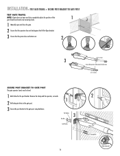
... is not assembled correctly you will require. 1 LEFT-HAND GATE RIGHT-HAND GATE 12 NOTE: If the Pull-to-Open bracket is now in manual mode. SEE ACCESSORIES) The Push-to-Open bracket can be assembled to work on a Left-Hand or a Right-Hand gate. 1 Review the gate types and select the type of installation you will...
... is not assembled correctly you will require. 1 LEFT-HAND GATE RIGHT-HAND GATE 12 NOTE: If the Pull-to-Open bracket is now in manual mode. SEE ACCESSORIES) The Push-to-Open bracket can be assembled to work on a Left-Hand or a Right-Hand gate. 1 Review the gate types and select the type of installation you will...
LA400 Manual
Page 15
...of this manual. Gate Post Gate Hinge Point Gate Post Gate Hinge Point Gate Post Gate Hinge Point Operator Hinge Point 7" (18 cm) 7" (18 cm) Operator 7" (18 cm) Hinge Point 7" (18 cm) Operator 7" (18 cm) Hinge Point 7" (18 cm) Gate Post Gate Hinge Point Gate Post Gate Hinge Point Gate Post Gate Hinge Point... on the back page of metal or wood) to the gate post to -Open bracket. INSTALLATION » DETERMINE MOUNTING LOCATION + MEASURING AND MARKING FOR THE GATE BRACKET DETERMINE MOUNTING LOCATION The gate post bracket assembly can be mounted several places on preference. ...
...of this manual. Gate Post Gate Hinge Point Gate Post Gate Hinge Point Gate Post Gate Hinge Point Operator Hinge Point 7" (18 cm) 7" (18 cm) Operator 7" (18 cm) Hinge Point 7" (18 cm) Operator 7" (18 cm) Hinge Point 7" (18 cm) Gate Post Gate Hinge Point Gate Post Gate Hinge Point Gate Post Gate Hinge Point... on the back page of metal or wood) to the gate post to -Open bracket. INSTALLATION » DETERMINE MOUNTING LOCATION + MEASURING AND MARKING FOR THE GATE BRACKET DETERMINE MOUNTING LOCATION The gate post bracket assembly can be mounted several places on preference. ...
LA400 Manual
Page 17
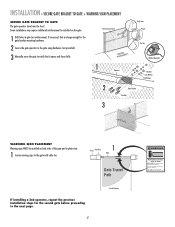
INSTALLATION » TEST GATE TRAVEL + SECURE POST BRACKET TO GATE POST TEST GATE TRAVEL NOTE: If gate does not open and close completely adjust the position of the 1 gate bracket and mark new mounting holes. 1 Manually open and close the gate. 2 Ensure that the operator does not bind against the Pull-to-Open bracket. 3 Ensure that the piston does not bottom...
INSTALLATION » TEST GATE TRAVEL + SECURE POST BRACKET TO GATE POST TEST GATE TRAVEL NOTE: If gate does not open and close completely adjust the position of the 1 gate bracket and mark new mounting holes. 1 Manually open and close the gate. 2 Ensure that the operator does not bind against the Pull-to-Open bracket. 3 Ensure that the piston does not bottom...
LA400 Manual
Page 18
... that it opens and closes fully. Gate may require additional reinforcement be installed on the gate. 1 Drill holes in the gate area. Some installations may move the gate to the gate using hardware (not provided). 3 Manually move at any time without prior warning. INSTALLATION » SECURE GATE BRACKET TO GATE + WARNING SIGN PLACEMENT SECURE GATE BRACKET TO GATE The gate operator (arm...
... that it opens and closes fully. Gate may require additional reinforcement be installed on the gate. 1 Drill holes in the gate area. Some installations may move the gate to the gate using hardware (not provided). 3 Manually move at any time without prior warning. INSTALLATION » SECURE GATE BRACKET TO GATE + WARNING SIGN PLACEMENT SECURE GATE BRACKET TO GATE The gate operator (arm...
LA400 Manual
Page 40
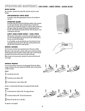
...The next command given by pressing the reset button. MANUAL RELEASE In case of the remote control will require resetting. This locks the release lever. 3 Remove the key and store in the open the gate. No commands will close the gate and return the operator to normal operation. This engages ... 180°. OPERATION AND MAINTENANCE » RESET BUTTON + REMOTE CONTROL + MANUAL RELEASE RESET BUTTON The reset button is located on the outside of time you wish to leave the gate(s) in the open the gate fully, then press the reset button. Reset the control board by remote control...
...The next command given by pressing the reset button. MANUAL RELEASE In case of the remote control will require resetting. This locks the release lever. 3 Remove the key and store in the open the gate. No commands will close the gate and return the operator to normal operation. This engages ... 180°. OPERATION AND MAINTENANCE » RESET BUTTON + REMOTE CONTROL + MANUAL RELEASE RESET BUTTON The reset button is located on the outside of time you wish to leave the gate(s) in the open the gate fully, then press the reset button. Reset the control board by remote control...

LA400 Pull to Open Addendum Manual
Page 1
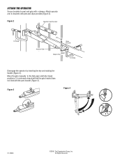
... (Figure 1). Place opener against gate post and adjust the opener until the required dimension is being added to the LA400, offering greater mounting flexibility. Ideally, the distance between and opener hinge points should be used to mount operator if needed Addendum to 30-degrees of this hole helps add up to LA400 Owner's Manual Acceptable Configurations (will...
... (Figure 1). Place opener against gate post and adjust the opener until the required dimension is being added to the LA400, offering greater mounting flexibility. Ideally, the distance between and opener hinge points should be used to mount operator if needed Addendum to 30-degrees of this hole helps add up to LA400 Owner's Manual Acceptable Configurations (will...
LA400 Pull to Open Addendum Manual
Page 2
Figure 2 Operator must be level C-Clamp Actuator Side Pin Gate Bracket Hairpin Clip C-Clamp Disengage the operator by inserting the key and rotating the handle (Figure 3). Move the gate manually to post and gate with c-clamps. Figure 3 Figure 4 01-33464 ©2006, The Chamberlain Group, Inc. It is extremely important that the gate bracket does not bind with pins and clips provided (Figure 2). All Rights Reserved Attach operator arm to brackets with the post bracket (Figure 4). ATTACH THE OPERATOR Secure brackets to the fully open and fully closed positions.
Figure 2 Operator must be level C-Clamp Actuator Side Pin Gate Bracket Hairpin Clip C-Clamp Disengage the operator by inserting the key and rotating the handle (Figure 3). Move the gate manually to post and gate with c-clamps. Figure 3 Figure 4 01-33464 ©2006, The Chamberlain Group, Inc. It is extremely important that the gate bracket does not bind with pins and clips provided (Figure 2). All Rights Reserved Attach operator arm to brackets with the post bracket (Figure 4). ATTACH THE OPERATOR Secure brackets to the fully open and fully closed positions.


