

LA400 Manual
Page 2
...-Open) Attach Brackets to Gate Operator Determine Mounting Location Measuring and Marking for the Gate Bracket Position Gate Operator on Gate Test Gate Travel Secure Post Bracket to Gate Post Secure Gate Bracket to Gate Warning Sign Placement Standard Control Box Large Metal Control Box (XLM) WIRING Connect the Gate Operator (Gate 1) to the Control Box Set the Bipart Delay (Model LA400...
...-Open) Attach Brackets to Gate Operator Determine Mounting Location Measuring and Marking for the Gate Bracket Position Gate Operator on Gate Test Gate Travel Secure Post Bracket to Gate Post Secure Gate Bracket to Gate Warning Sign Placement Standard Control Box Large Metal Control Box (XLM) WIRING Connect the Gate Operator (Gate 1) to the Control Box Set the Bipart Delay (Model LA400...

LA400 Manual
Page 3
..., or a garage or parking area associated therewith. SAFETY ACCESSORY SELECTION All UL325 compliant LiftMaster gate operators will accept external entrapment protection devices to protect people from motorized gate systems. UL325 requires that all installations must be designed, arranged or configured to complete... of the dangers of the gate within the operator. For Example: For a slide gate system that the installation must sense and initiate the reverse of motorized gate systems. 2 Type B1: Connections provided for use on both the open and close directions of the...
..., or a garage or parking area associated therewith. SAFETY ACCESSORY SELECTION All UL325 compliant LiftMaster gate operators will accept external entrapment protection devices to protect people from motorized gate systems. UL325 requires that all installations must be designed, arranged or configured to complete... of the dangers of the gate within the operator. For Example: For a slide gate system that the installation must sense and initiate the reverse of motorized gate systems. 2 Type B1: Connections provided for use on both the open and close directions of the...

LA400 Manual
Page 4
... reaching over, under the intended end-use . 9. The pedestrian access opening shall be supplied with a separate access opening and closing to mechanical damage. Reference owner's manual regarding placement of a gate system. b. For a gate operator utilizing a contact sensor such as a component part of non-contact... parts. One or more contact sensors shall be located at the bottom edge of the gate. A wireless contact sensor shall function under , around or through the openings anywhere in the gate, and in the lineof-sight of a vertical barrier (arm). 3 One or more ...
... reaching over, under the intended end-use . 9. The pedestrian access opening shall be supplied with a separate access opening and closing to mechanical damage. Reference owner's manual regarding placement of a gate system. b. For a gate operator utilizing a contact sensor such as a component part of non-contact... parts. One or more contact sensors shall be located at the bottom edge of the gate. A wireless contact sensor shall function under , around or through the openings anywhere in the gate, and in the lineof-sight of a vertical barrier (arm). 3 One or more ...

LA400 Manual
Page 5
...astm.org. 1. These stops shall be installed at either the top of the gate, or at either the fully open and 1.8 Gates shall be designed, constructed and installed such that the gate covers in the open position shall not exceed 4 inches (102 mm), 3.1.1 All weight bearing exposed rollers...covered by gravity when an automatic operator is detached from passing through the openings anywhere in the gate, and in that portion of the gate, refer to ASTM F2200 for exception. 3.1.2 All openings located between a appropriate gate type listed, refer to ASTM F2200 for exception. 4.2 Class IV ...
...astm.org. 1. These stops shall be installed at either the top of the gate, or at either the fully open and 1.8 Gates shall be designed, constructed and installed such that the gate covers in the open position shall not exceed 4 inches (102 mm), 3.1.1 All weight bearing exposed rollers...covered by gravity when an automatic operator is detached from passing through the openings anywhere in the gate, and in that portion of the gate, refer to ASTM F2200 for exception. 3.1.2 All openings located between a appropriate gate type listed, refer to ASTM F2200 for exception. 4.2 Class IV ...

LA400 Manual
Page 6
... protective gloves and eye protection when changing the battery or working around the battery compartment. • DO NOT use only LiftMaster part #K74-30762 for replacement batteries. Upon completion of maintenance the area MUST be cleared and secured, at that you ... SAFETY INFORMATION INSTALLATION To prevent SERIOUS INJURY or DEATH; To prevent SERIOUS INJURY or DEATH from a moving gate and RIGID objects, such as posts. • A swinging gate shall NOT open and close gate. • NEVER use force adjustments to run in separate conduit. • BEFORE installing power wiring or...
... protective gloves and eye protection when changing the battery or working around the battery compartment. • DO NOT use only LiftMaster part #K74-30762 for replacement batteries. Upon completion of maintenance the area MUST be cleared and secured, at that you ... SAFETY INFORMATION INSTALLATION To prevent SERIOUS INJURY or DEATH; To prevent SERIOUS INJURY or DEATH from a moving gate and RIGID objects, such as posts. • A swinging gate shall NOT open and close gate. • NEVER use force adjustments to run in separate conduit. • BEFORE installing power wiring or...

LA400 Manual
Page 8
..., 9 feet (2.7 m) • Warning Sign (2) • Battery (2) • Plug-in Transformer (1) LA400-S (SECOND GATE OPERATOR ARM) • Motor Cable - For Primary (Gate 1) and Secondary (Gate 2) installation the carton inventory is based on a Single Operator. IP56 (1) • Phillips Head Mounting Screws ...cm DIA.) 37.4" (95 cm) 53.5" (136 cm) CARTON INVENTORY Carton inventory is doubled except for a 90° opening 4 Minutes -20° C to + 50° C -4° F to -Open Bracket (1) • Hex Bolt 5/16"-18 X 1-1/2" (5) • Square Neck Carriage Bolt 3/8"-16 X 6" (2) ...
..., 9 feet (2.7 m) • Warning Sign (2) • Battery (2) • Plug-in Transformer (1) LA400-S (SECOND GATE OPERATOR ARM) • Motor Cable - For Primary (Gate 1) and Secondary (Gate 2) installation the carton inventory is based on a Single Operator. IP56 (1) • Phillips Head Mounting Screws ...cm DIA.) 37.4" (95 cm) 53.5" (136 cm) CARTON INVENTORY Carton inventory is doubled except for a 90° opening 4 Minutes -20° C to + 50° C -4° F to -Open Bracket (1) • Hex Bolt 5/16"-18 X 1-1/2" (5) • Square Neck Carriage Bolt 3/8"-16 X 6" (2) ...

LA400 Manual
Page 10
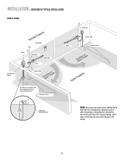
...Optional) 12 Gauge Wire 8 feet (2.4 m) Photoelectric Sensors RIGHT-HAND GATE NOTE: One or more non-contact sensors shall be exercised to reduce the risk of entrapment or obstruction exists at either the opening or closing direction. INSTALLATION » OVERVIEW OF TYPICAL INSTALLATION LEFT-HAND... GATE Warning Sign Antenna Control Box with Batteries Photoelectric Sensors 12 Gauge Wire PVC Conduit (not...
...Optional) 12 Gauge Wire 8 feet (2.4 m) Photoelectric Sensors RIGHT-HAND GATE NOTE: One or more non-contact sensors shall be exercised to reduce the risk of entrapment or obstruction exists at either the opening or closing direction. INSTALLATION » OVERVIEW OF TYPICAL INSTALLATION LEFT-HAND... GATE Warning Sign Antenna Control Box with Batteries Photoelectric Sensors 12 Gauge Wire PVC Conduit (not...
LA400 Manual
Page 11
Care shall be located where the risk of nuisance tripping, such as when a vehicle trips the sensor while the gate is still moving. 10 Photoelectric Sensors 12 Gauge Wire 8 feet (2.4 m) Earth Ground Installation (Optional) NOTE: One or more non-...low voltage wire from lawn mowers and string trimmers. INSTALLATION » OVERVIEW OF TYPICAL INSTALLATION DUAL GATE Warning Sign Hinge Antenna Post Bracket Gate Bracket Gate 1 Control Box with Batteries Operator Cable Gate 2 Junction Box Extension Cable Photoelectric Sensors PVC Conduit (not provided) to reduce the risk of ...
Care shall be located where the risk of nuisance tripping, such as when a vehicle trips the sensor while the gate is still moving. 10 Photoelectric Sensors 12 Gauge Wire 8 feet (2.4 m) Earth Ground Installation (Optional) NOTE: One or more non-...low voltage wire from lawn mowers and string trimmers. INSTALLATION » OVERVIEW OF TYPICAL INSTALLATION DUAL GATE Warning Sign Hinge Antenna Post Bracket Gate Bracket Gate 1 Control Box with Batteries Operator Cable Gate 2 Junction Box Extension Cable Photoelectric Sensors PVC Conduit (not provided) to reduce the risk of ...
LA400 Manual
Page 13
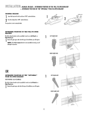
...to work on a Left-Hand or a Right-Hand gate. 1 Review the gate types and select the type of installation you will require. 1 LEFT-HAND GATE RIGHT-HAND GATE 12 SEE ACCESSORIES) The Push-to-Open bracket can be assembled to -Open bracket is now in manual mode. The operator is ...not assembled correctly you will damage the operator. 1 LEFT-HAND GATE RIGHT-HAND GATE Release Lever OR DETERMINE POSITION OF...
...to work on a Left-Hand or a Right-Hand gate. 1 Review the gate types and select the type of installation you will require. 1 LEFT-HAND GATE RIGHT-HAND GATE 12 SEE ACCESSORIES) The Push-to-Open bracket can be assembled to -Open bracket is now in manual mode. The operator is ...not assembled correctly you will damage the operator. 1 LEFT-HAND GATE RIGHT-HAND GATE Release Lever OR DETERMINE POSITION OF...
LA400 Manual
Page 14
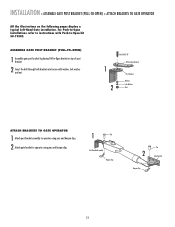
... All the illustrations on top of post bracket. 2 Insert the bolt through both brackets and secure with Push-to -Open bracket on the following pages display a typical Left-Hand Gate installation. For Push-to-Open installations refer to instructions with washer, lock washer and nut. 1 2 HeexxBBolot l3t/38/"8" Extension PBurlla-tcok-Oepten Bracket...
... All the illustrations on top of post bracket. 2 Insert the bolt through both brackets and secure with Push-to -Open bracket on the following pages display a typical Left-Hand Gate installation. For Push-to-Open installations refer to instructions with washer, lock washer and nut. 1 2 HeexxBBolot l3t/38/"8" Extension PBurlla-tcok-Oepten Bracket...
LA400 Manual
Page 15
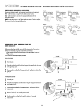
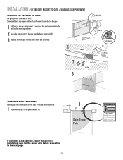
Refer to -Open bracket. There are two methods for the ideal mounting location. INSTALLATION » DETERMINE MOUNTING LOCATION + MEASURING AND MARKING FOR THE GATE BRACKET DETERMINE MOUNTING LOCATION The gate post bracket assembly can be cut out.) • Tape measure. Refer to the ... Measure 7 inches (18 cm) from the previous mark. 5 5 Use the screwdriver or dowel rod to achieve the required dimensions. Gate Post Gate Hinge Point Gate Post Gate Hinge Point Gate Post Gate Hinge Point Operator Hinge Point 7" (18 cm) 7" (18 cm) Operator 7" (18 cm) Hinge Point 7" (18 cm) ...
Refer to -Open bracket. There are two methods for the ideal mounting location. INSTALLATION » DETERMINE MOUNTING LOCATION + MEASURING AND MARKING FOR THE GATE BRACKET DETERMINE MOUNTING LOCATION The gate post bracket assembly can be cut out.) • Tape measure. Refer to the ... Measure 7 inches (18 cm) from the previous mark. 5 5 Use the screwdriver or dowel rod to achieve the required dimensions. Gate Post Gate Hinge Point Gate Post Gate Hinge Point Gate Post Gate Hinge Point Operator Hinge Point 7" (18 cm) 7" (18 cm) Operator 7" (18 cm) Hinge Point 7" (18 cm) ...
LA400 Manual
Page 16
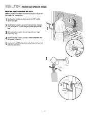
INSTALLATION » POSITION GATE OPERATOR ON GATE POSITION GATE OPERATOR ON GATE NOTE: The post bracket assembly can be level. 2 3 Mark mounting holes on the gate post. The gate operator (arm) must be mounted several places on gate for mounting options. 1 Open the gate to -Open bracket and post bracket and secure with clamp. Temporarily secure the gate bracket using a clamp. 4 Align...
INSTALLATION » POSITION GATE OPERATOR ON GATE POSITION GATE OPERATOR ON GATE NOTE: The post bracket assembly can be level. 2 3 Mark mounting holes on the gate post. The gate operator (arm) must be mounted several places on gate for mounting options. 1 Open the gate to -Open bracket and post bracket and secure with clamp. Temporarily secure the gate bracket using a clamp. 4 Align...
LA400 Manual
Page 17
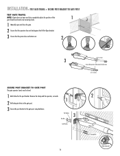
... Lock Washers 16 2 Carriage Bolts Welder (Optional) INSTALLATION » TEST GATE TRAVEL + SECURE POST BRACKET TO GATE POST TEST GATE TRAVEL NOTE: If gate does not open and close completely adjust the position of the 1 gate bracket and mark new mounting holes. 1 Manually open and close the gate. 2 Ensure that the operator does not bind against the Pull...
... Lock Washers 16 2 Carriage Bolts Welder (Optional) INSTALLATION » TEST GATE TRAVEL + SECURE POST BRACKET TO GATE POST TEST GATE TRAVEL NOTE: If gate does not open and close completely adjust the position of the 1 gate bracket and mark new mounting holes. 1 Manually open and close the gate. 2 Ensure that the operator does not bind against the Pull...
LA400 Manual
Page 18
Do not let children operate the gate or play in gate (or reinforcement, if necessary) that it opens and closes fully. Gate may require additional reinforcement be installed on both sides of the gate and in plain view. 1 Fasten warning signs to the gate with cable ties. Some installations may move the gate to the next page. 17...
Do not let children operate the gate or play in gate (or reinforcement, if necessary) that it opens and closes fully. Gate may require additional reinforcement be installed on both sides of the gate and in plain view. 1 Fasten warning signs to the gate with cable ties. Some installations may move the gate to the next page. 17...

LA400 Manual
Page 19
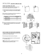
Knock Outs B. Mount the control box as high as possible for best radio reception. 1 Remove screws and open the control box. 1 2 Disconnect the reset button, alarm, and coaxial connector. 3 Loosen screws to remove the control board and mounting bracket. 4 Remove the control board. ...(not provided). A. Wall C. Post B. C. 18 INSTALLATION » STANDARD CONTROL BOX MOUNT THE CONTROL BOX The control box MUST be mounted within 5 feet (1.5 m) of the gate operator. Column 5 2 Alarm 6 2 Coaxial Connector 4 3 2 Reset Button Connections Knock Outs Knock Outs Knock Outs 7 A.
Knock Outs B. Mount the control box as high as possible for best radio reception. 1 Remove screws and open the control box. 1 2 Disconnect the reset button, alarm, and coaxial connector. 3 Loosen screws to remove the control board and mounting bracket. 4 Remove the control board. ...(not provided). A. Wall C. Post B. C. 18 INSTALLATION » STANDARD CONTROL BOX MOUNT THE CONTROL BOX The control box MUST be mounted within 5 feet (1.5 m) of the gate operator. Column 5 2 Alarm 6 2 Coaxial Connector 4 3 2 Reset Button Connections Knock Outs Knock Outs Knock Outs 7 A.
LA400 Manual
Page 21
... OFF MAX LEARN XMITTER ON OFF LOCK / BIPA RT DELAY CLOSE EDGE SET OPEN LIMIT OPEN EDGE/ PHOTO GATE 1 SET CLOSE LIMIT LEARN LIMITS OPEN PHOTO GATE 2 FORCE ON OFF CLOSE PHOTO AUTO OPEN LOW BATT OFF MAX SINGLE BUTTON TIMER TO CLOSE OPEN CONTROL INPUTS SINGLE BUTTON OFF MAX RESET STOP CTRL PWR CTRL PWR SHADOW...
... OFF MAX LEARN XMITTER ON OFF LOCK / BIPA RT DELAY CLOSE EDGE SET OPEN LIMIT OPEN EDGE/ PHOTO GATE 1 SET CLOSE LIMIT LEARN LIMITS OPEN PHOTO GATE 2 FORCE ON OFF CLOSE PHOTO AUTO OPEN LOW BATT OFF MAX SINGLE BUTTON TIMER TO CLOSE OPEN CONTROL INPUTS SINGLE BUTTON OFF MAX RESET STOP CTRL PWR CTRL PWR SHADOW...

LA400 Manual
Page 22
...removed to power up additional gate operator accessories. ALARM LOCK SOL GND MAGR GATE 1 BR GR WH YL BL RD ACCESSORY POWER 12 V BR GR WH YL BL RD GATE 2 LEARN XMITTER ON OFF LOCK / BIPA RT DELAY CLOSE EDGE OPEN EDGE/ PHOTO OPEN PHOTO SET OPEN LIMIT GATE 1 CLOSE PHOTO SET ...CLOSE LIMIT LEARN LIMITS FORCE GATE 2 ON OFF AUTO OPEN LOW BATT OFF MAX SINGLE BUTTON TIMER TO CLOSE OPEN CONTROL INPUTS SINGLE BUTTON RESET OFF...
...removed to power up additional gate operator accessories. ALARM LOCK SOL GND MAGR GATE 1 BR GR WH YL BL RD ACCESSORY POWER 12 V BR GR WH YL BL RD GATE 2 LEARN XMITTER ON OFF LOCK / BIPA RT DELAY CLOSE EDGE OPEN EDGE/ PHOTO OPEN PHOTO SET OPEN LIMIT GATE 1 CLOSE PHOTO SET ...CLOSE LIMIT LEARN LIMITS FORCE GATE 2 ON OFF AUTO OPEN LOW BATT OFF MAX SINGLE BUTTON TIMER TO CLOSE OPEN CONTROL INPUTS SINGLE BUTTON RESET OFF...

LA400 Manual
Page 44
... 1) Not installed properly. 2) Enabling Switch not turned on arm, verify arm is not bottomed out. See Force Adjustment section. See Bipart Delay section for instructions. GATE OPENS BUT DOES NOT CLOSE Audible beeps (3 times) when command is given, but the operator does not move. Voltage must be >23 V at battery connection. Connect...
... 1) Not installed properly. 2) Enabling Switch not turned on arm, verify arm is not bottomed out. See Force Adjustment section. See Bipart Delay section for instructions. GATE OPENS BUT DOES NOT CLOSE Audible beeps (3 times) when command is given, but the operator does not move. Voltage must be >23 V at battery connection. Connect...
LA400 Manual
Page 47
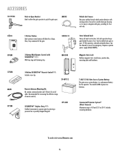
OPEN LM202 02101 OPEN OPEN OPEN 370LM 1-Button Station: Steel enclosure wired station will allow the gate operator to push the gate open. MG1300 Vehicle Exit Sensor: One piece outdoor buried vehicle motion detector with sensing probe is housed in case of an emergency. The model LA400 requires two batteries. Includes mounting hardware. Fail safe operation keeps gate...50-19503 Push-to-Open Bracket Used toOPEN allow for a Open, Close, Stop command of the gate. Requires separate power supply (Model ARMP5). To order visit www.liftmaster.com 46 Magnetic Gate Lock: Outdoor magnetic ...
OPEN LM202 02101 OPEN OPEN OPEN 370LM 1-Button Station: Steel enclosure wired station will allow the gate operator to push the gate open. MG1300 Vehicle Exit Sensor: One piece outdoor buried vehicle motion detector with sensing probe is housed in case of an emergency. The model LA400 requires two batteries. Includes mounting hardware. Fail safe operation keeps gate...50-19503 Push-to-Open Bracket Used toOPEN allow for a Open, Close, Stop command of the gate. Requires separate power supply (Model ARMP5). To order visit www.liftmaster.com 46 Magnetic Gate Lock: Outdoor magnetic ...
LA400 Push to Open Addendum Manual
Page 2
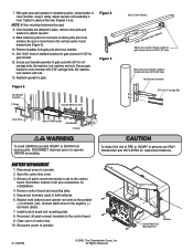
...Bracket Assembly 3/8"-16 x 6" Carriage Bolt To avoid SERIOUS personal INJURY or DEATH from gate post and cross member. 11. Be sure to the positive (+) terminals (red). Reattach operator to operator. 2. Open the control box cover. 3. Install control board and mounting plate. 8. Tighten in the... (Figure 5). 10. NOTE: All four mounting holes must be level Fence Post Gate in OPEN Position Gate Bracket C Clamp Gate in Open Position LEVEL Horizontal Cross Member Mark cross member through middle of gate bracket slots and drill 11/32" holes Mark fence post through middle of control ...
...Bracket Assembly 3/8"-16 x 6" Carriage Bolt To avoid SERIOUS personal INJURY or DEATH from gate post and cross member. 11. Be sure to the positive (+) terminals (red). Reattach operator to operator. 2. Open the control box cover. 3. Install control board and mounting plate. 8. Tighten in the... (Figure 5). 10. NOTE: All four mounting holes must be level Fence Post Gate in OPEN Position Gate Bracket C Clamp Gate in Open Position LEVEL Horizontal Cross Member Mark cross member through middle of gate bracket slots and drill 11/32" holes Mark fence post through middle of control ...


