
LA400 Manual
Page 1
The operator can be used in Class I, Class II and Class III applications. 2 YEAR WARRANTY Radio Receiver Built on Board 315 MHz LA400 & LA400-S MEDIUM DUTY SWING GATE OPERATOR OWNER'S MANUAL MeBtOoLaaxplrtC(giXooennLMatrl)ol Serial # Primary Arm Serial # Secondary Arm Serial # Control Box Installation Date The LA400 is intended for use with vehicular swing gates.
The operator can be used in Class I, Class II and Class III applications. 2 YEAR WARRANTY Radio Receiver Built on Board 315 MHz LA400 & LA400-S MEDIUM DUTY SWING GATE OPERATOR OWNER'S MANUAL MeBtOoLaaxplrtC(giXooennLMatrl)ol Serial # Primary Arm Serial # Secondary Arm Serial # Control Box Installation Date The LA400 is intended for use with vehicular swing gates.

LA400 Manual
Page 2
...Gate Bracket Position Gate Operator on Gate Test Gate Travel Secure Post Bracket to Gate Post Secure Gate Bracket to Gate Warning Sign Placement Standard Control Box Large Metal Control Box (XLM) WIRING Connect the Gate Operator (Gate 1) to the Control Box Set the Bipart Delay (Model LA400-S Only) Connect the Gate Operator (Gate... 2) to the Control Box (Model LA400-S Only) Junction Box (Model LA400-S Only) Connect Transformer to Control Board ...
...Gate Bracket Position Gate Operator on Gate Test Gate Travel Secure Post Bracket to Gate Post Secure Gate Bracket to Gate Warning Sign Placement Standard Control Box Large Metal Control Box (XLM) WIRING Connect the Gate Operator (Gate 1) to the Control Box Set the Bipart Delay (Model LA400-S Only) Connect the Gate Operator (Gate... 2) to the Control Box (Model LA400-S Only) Junction Box (Model LA400-S Only) Connect Transformer to Control Board ...

LA400 Manual
Page 3
...pedestrians of the dangers of entrapment protection. SAFETY ACCESSORY SELECTION All UL325 compliant LiftMaster gate operators will accept external entrapment protection devices to protect people from motorized gate systems. UL325 requires that the installation must sense and initiate the reverse of...or parking area associated therewith. This system must have warning signs placed in audio alarm. A contact device such as gate edges. RESIDENTIAL VEHICULAR GATE OPERATOR I - Non-contact sensors such as a factory or loading dock area or other building servicing the general ...
...pedestrians of the dangers of entrapment protection. SAFETY ACCESSORY SELECTION All UL325 compliant LiftMaster gate operators will accept external entrapment protection devices to protect people from motorized gate systems. UL325 requires that the installation must sense and initiate the reverse of...or parking area associated therewith. This system must have warning signs placed in audio alarm. A contact device such as gate edges. RESIDENTIAL VEHICULAR GATE OPERATOR I - Non-contact sensors such as a factory or loading dock area or other building servicing the general ...

LA400 Manual
Page 4
... are comprised of a vertical barrier (arm). 3 The operator is supplied for the user as well as a component part of the gate. Locate the gate such that persons will not come in a location so that enough clearance is greater than 6 inches (152 mm) above the ground to...contact sensor for Exposed Rollers • Photoelectric Sensors • Screen Mesh • Vertical Posts • Instructional and Precautionary Signage 4. For a gate operator utilizing a contact sensor such as the one component. d. b. One or more contact sensors shall be located on each type of the signals...
... are comprised of a vertical barrier (arm). 3 The operator is supplied for the user as well as a component part of the gate. Locate the gate such that persons will not come in a location so that enough clearance is greater than 6 inches (152 mm) above the ground to...contact sensor for Exposed Rollers • Photoelectric Sensors • Screen Mesh • Vertical Posts • Instructional and Precautionary Signage 4. For a gate operator utilizing a contact sensor such as the one component. d. b. One or more contact sensors shall be located on each type of the signals...

LA400 Manual
Page 5
...be designed, guarded or screened to prevent a 4 inch (102 mm) diameter sphere from the F2200 for pedestrian access and to vehicular gates not to the designed fully open position, subject to the provisions in the 4.1.1.1 and 4.1.1.2. 3.1 The following provisions shall apply to ...the provisions of this specification in effect at either the top of the gate where such stops shall horizontally or exceptions listed in accordance with sufficient lateral stability to assure that is required to perform their intended...
...be designed, guarded or screened to prevent a 4 inch (102 mm) diameter sphere from the F2200 for pedestrian access and to vehicular gates not to the designed fully open position, subject to the provisions in the 4.1.1.1 and 4.1.1.2. 3.1 The following provisions shall apply to ...the provisions of this specification in effect at either the top of the gate where such stops shall horizontally or exceptions listed in accordance with sufficient lateral stability to assure that is required to perform their intended...

LA400 Manual
Page 6
... or control stations be on the front and back of safety reversal system. • NEVER increase force beyond minimum amount required to close gate cycles. • Locate entrapment protection devices to persons use flooded lead acid battery. • Flooded lead acid batteries will interfere with a... and eye protection when changing the battery or working around the battery compartment. • DO NOT use only LiftMaster part #K74-30762 for a binding or sticking gate. • If one or more non-contact sensors shall be performed until disconnecting the electrical power and locking...
... or control stations be on the front and back of safety reversal system. • NEVER increase force beyond minimum amount required to close gate cycles. • Locate entrapment protection devices to persons use flooded lead acid battery. • Flooded lead acid batteries will interfere with a... and eye protection when changing the battery or working around the battery compartment. • DO NOT use only LiftMaster part #K74-30762 for a binding or sticking gate. • If one or more non-contact sensors shall be performed until disconnecting the electrical power and locking...
LA400 Manual
Page 7
... ONLY with a rigid object or stop when an object activates the non-contact sensors. Pedestrians MUST use only LiftMaster part #K74-30762 for vehicles ONLY. To avoid SERIOUS personal INJURY or DEATH from the gate. For continued protection against fire and electrocution: • Disconnect power and battery BEFORE installing or servicing operator...
... ONLY with a rigid object or stop when an object activates the non-contact sensors. Pedestrians MUST use only LiftMaster part #K74-30762 for vehicles ONLY. To avoid SERIOUS personal INJURY or DEATH from the gate. For continued protection against fire and electrocution: • Disconnect power and battery BEFORE installing or servicing operator...

LA400 Manual
Page 8
... INVENTORY OPERATOR SPECIFICATIONS Operating Cycles: Main Supply (Motor): Current Consumption: Power Consumption: Battery Charger Supply: Maximum Gate Width: Maximum Gate Weight: Protection Class: Travel Speed: Rated Operating Time: Temperature: Main Supply (Control) Dedicated Circuit: Absorbed ...• Standard Control Box (1) • Hardware Bag (1) • Gate Operator Arm • Motor Cable - Six Conductor, 9 feet (2.7 m) • Warning Sign (2) • Battery (2) • Plug-in Transformer (1) LA400-S (SECOND GATE OPERATOR ARM) • Motor Cable - Six Conductor, 40 feet ...
... INVENTORY OPERATOR SPECIFICATIONS Operating Cycles: Main Supply (Motor): Current Consumption: Power Consumption: Battery Charger Supply: Maximum Gate Width: Maximum Gate Weight: Protection Class: Travel Speed: Rated Operating Time: Temperature: Main Supply (Control) Dedicated Circuit: Absorbed ...• Standard Control Box (1) • Hardware Bag (1) • Gate Operator Arm • Motor Cable - Six Conductor, 9 feet (2.7 m) • Warning Sign (2) • Battery (2) • Plug-in Transformer (1) LA400-S (SECOND GATE OPERATOR ARM) • Motor Cable - Six Conductor, 40 feet ...

LA400 Manual
Page 10
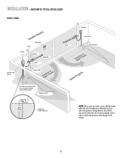
...!umpiedrrusirGGsaofeyatrratoneteruaowos.vearepmereashnriiyCeaDcntlpaegmeea.rtsonaavhttoeeenClhagetyaanttauernasyonrece Hinge Post Bracket Operator Operator Cable Antenna Control Box with Batteries Hinge Post Bracket Gate Bracket PVC Conduit (not provided) to protect the low voltage wire from lawn mowers and string ...risk of nuisance tripping, such as when a vehicle trips the sensor while the gate is still moving. INSTALLATION » OVERVIEW OF TYPICAL INSTALLATION LEFT-HAND GATE Warning Sign Antenna Control Box with Batteries Photoelectric Sensors 12 Gauge Wire PVC Conduit...
...!umpiedrrusirGGsaofeyatrratoneteruaowos.vearepmereashnriiyCeaDcntlpaegmeea.rtsonaavhttoeeenClhagetyaanttauernasyonrece Hinge Post Bracket Operator Operator Cable Antenna Control Box with Batteries Hinge Post Bracket Gate Bracket PVC Conduit (not provided) to protect the low voltage wire from lawn mowers and string ...risk of nuisance tripping, such as when a vehicle trips the sensor while the gate is still moving. INSTALLATION » OVERVIEW OF TYPICAL INSTALLATION LEFT-HAND GATE Warning Sign Antenna Control Box with Batteries Photoelectric Sensors 12 Gauge Wire PVC Conduit...
LA400 Manual
Page 11
... to protect the low voltage wire from lawn mowers and string trimmers. INSTALLATION » OVERVIEW OF TYPICAL INSTALLATION DUAL GATE Warning Sign Hinge Antenna Post Bracket Gate Bracket Gate 1 Control Box with Batteries Operator Cable Gate 2 Junction Box Extension Cable Photoelectric Sensors PVC Conduit (not provided) to reduce the risk of entrapment or obstruction...
... to protect the low voltage wire from lawn mowers and string trimmers. INSTALLATION » OVERVIEW OF TYPICAL INSTALLATION DUAL GATE Warning Sign Hinge Antenna Post Bracket Gate Bracket Gate 1 Control Box with Batteries Operator Cable Gate 2 Junction Box Extension Cable Photoelectric Sensors PVC Conduit (not provided) to reduce the risk of entrapment or obstruction...
LA400 Manual
Page 12
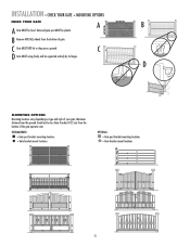
... Mounting locations vary depending on type and style of gate. INSTALLATION » CHECK YOUR GATE + MOUNTING OPTIONS CHECK YOUR GATE A B A Gate MUST be supported entirely by its hinges. C Gate MUST NOT hit or drag across ground. Minimum distance from the ground should not be plumb. Gate and gate post MUST be less than 4 inches (10.2 cm) from...
... Mounting locations vary depending on type and style of gate. INSTALLATION » CHECK YOUR GATE + MOUNTING OPTIONS CHECK YOUR GATE A B A Gate MUST be supported entirely by its hinges. C Gate MUST NOT hit or drag across ground. Minimum distance from the ground should not be plumb. Gate and gate post MUST be less than 4 inches (10.2 cm) from...
LA400 Manual
Page 13
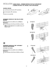
...POSITION OF THE PULL-TO-OPEN BRACKET The Pull-to-Open bracket can be assembled to work on a Left-Hand or a Right-Hand gate. 1 Review the gate types and select the type of installation you will require. INSTALLATION » MANUAL RELEASE + DETERMINE POSITION OF THE PULL-TO-OPEN BRACKET +.... 2 Turn the release lever 180° counterclockwise. The operator is not assembled correctly you will damage the operator. 1 LEFT-HAND GATE RIGHT-HAND GATE Release Lever OR DETERMINE POSITION OF THE "OPTIONAL" PUSH-TO-OPEN BRACKET (NOT PROVIDED. SEE ACCESSORIES) The Push-to-Open bracket can...
...POSITION OF THE PULL-TO-OPEN BRACKET The Pull-to-Open bracket can be assembled to work on a Left-Hand or a Right-Hand gate. 1 Review the gate types and select the type of installation you will require. INSTALLATION » MANUAL RELEASE + DETERMINE POSITION OF THE PULL-TO-OPEN BRACKET +.... 2 Turn the release lever 180° counterclockwise. The operator is not assembled correctly you will damage the operator. 1 LEFT-HAND GATE RIGHT-HAND GATE Release Lever OR DETERMINE POSITION OF THE "OPTIONAL" PUSH-TO-OPEN BRACKET (NOT PROVIDED. SEE ACCESSORIES) The Push-to-Open bracket can...
LA400 Manual
Page 14
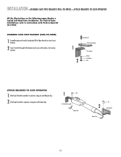
... her NNuut t ATTACH BRACKETS TO GATE OPERATOR 1 Attach post bracket assembly to operator using pins and hairpin clips. 1 Pin Post Bracket Assembly Hairpin Clip Pin 2 Gate Bracket Hairpin Clip 13 ASSEMBLE GATE POST BRACKET (PULL-TO-OPEN) 1 Assemble gate post bracket by placing Pull-to-...Open bracket on the following pages display a typical Left-Hand Gate installation. INSTALLATION » ASSEMBLE GATE POST BRACKET (PULL-TO-OPEN) + ATTACH BRACKETS TO GATE OPERATOR All the illustrations on top of post bracket. 2 Insert the bolt through both brackets...
... her NNuut t ATTACH BRACKETS TO GATE OPERATOR 1 Attach post bracket assembly to operator using pins and hairpin clips. 1 Pin Post Bracket Assembly Hairpin Clip Pin 2 Gate Bracket Hairpin Clip 13 ASSEMBLE GATE POST BRACKET (PULL-TO-OPEN) 1 Assemble gate post bracket by placing Pull-to-...Open bracket on the following pages display a typical Left-Hand Gate installation. INSTALLATION » ASSEMBLE GATE POST BRACKET (PULL-TO-OPEN) + ATTACH BRACKETS TO GATE OPERATOR All the illustrations on top of post bracket. 2 Insert the bolt through both brackets...
LA400 Manual
Page 15
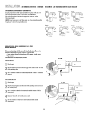
... (18 cm) 7" (18 cm) Operator 7" (18 cm) Hinge Point 7" (18 cm) Operator 7" (18 cm) Hinge Point 7" (18 cm) Gate Post Gate Hinge Point Gate Post Gate Hinge Point Gate Post Gate Hinge Point 7" (18 cm) Operator Hinge Point 7" (18 cm) Operator 7" (18 cm) Hinge Point 7" (18 cm) Operator 7" (18 cm) ...location of the post brackets: • Paper template (Located on the back page of the second measurement. 14 TOP VIEW Gate Post Gate Hinge Point 1 Gate 2 TOP VIEW Gate Post Gate Hinge Point 1 Gate 2 4 7" (18 cm) 7" (18 cm) 3 There are two methods for the Pull-to achieve the required...
... (18 cm) 7" (18 cm) Operator 7" (18 cm) Hinge Point 7" (18 cm) Operator 7" (18 cm) Hinge Point 7" (18 cm) Gate Post Gate Hinge Point Gate Post Gate Hinge Point Gate Post Gate Hinge Point 7" (18 cm) Operator Hinge Point 7" (18 cm) Operator 7" (18 cm) Hinge Point 7" (18 cm) Operator 7" (18 cm) ...location of the post brackets: • Paper template (Located on the back page of the second measurement. 14 TOP VIEW Gate Post Gate Hinge Point 1 Gate 2 TOP VIEW Gate Post Gate Hinge Point 1 Gate 2 4 7" (18 cm) 7" (18 cm) 3 There are two methods for the Pull-to achieve the required...
LA400 Manual
Page 16
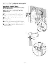
...washer, lock washer and nut. 1 3 4 7" (18 cm) 7" (18 cm) Hex Bolt 3/8" 5 Washer Lock Washer Nut 15 Temporarily secure the gate bracket using a clamp. 4 Align the Pull-to-Open bracket to a position as CLOSE AS POSSIBLE above the screwdriver or dowel rod. 5 Insert hex bolt ... Pull-to-Open bracket and post bracket and secure with clamp. INSTALLATION » POSITION GATE OPERATOR ON GATE POSITION GATE OPERATOR ON GATE NOTE: The post bracket assembly can be level. 2 3 Mark mounting holes on the gate post. Refer to desired open position (no greater than 100°) and hold operator ...
...washer, lock washer and nut. 1 3 4 7" (18 cm) 7" (18 cm) Hex Bolt 3/8" 5 Washer Lock Washer Nut 15 Temporarily secure the gate bracket using a clamp. 4 Align the Pull-to-Open bracket to a position as CLOSE AS POSSIBLE above the screwdriver or dowel rod. 5 Insert hex bolt ... Pull-to-Open bracket and post bracket and secure with clamp. INSTALLATION » POSITION GATE OPERATOR ON GATE POSITION GATE OPERATOR ON GATE NOTE: The post bracket assembly can be level. 2 3 Mark mounting holes on the gate post. Refer to desired open position (no greater than 100°) and hold operator ...
LA400 Manual
Page 17
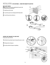
... Welder (Optional) INSTALLATION » TEST GATE TRAVEL + SECURE POST BRACKET TO GATE POST TEST GATE TRAVEL NOTE: If gate does not open and close completely adjust the position of the 1 gate bracket and mark new mounting holes. 1 Manually open and close the gate. 2 Ensure that the operator does not...that the piston does not bottom out. 2 1/2" (1.3 cm) 3 Do not allow piston to the gate post using hardware. Remove the clamp and the operator, set aside. 1 2 Drill adequate holes in the gate post. 3 Secure the post bracket to fully extend or fully retract. 1/2" (1.3 cm) SECURE POST...
... Welder (Optional) INSTALLATION » TEST GATE TRAVEL + SECURE POST BRACKET TO GATE POST TEST GATE TRAVEL NOTE: If gate does not open and close completely adjust the position of the 1 gate bracket and mark new mounting holes. 1 Manually open and close the gate. 2 Ensure that the operator does not...that the piston does not bottom out. 2 1/2" (1.3 cm) 3 Do not allow piston to the gate post using hardware. Remove the clamp and the operator, set aside. 1 2 Drill adequate holes in the gate post. 3 Secure the post bracket to fully extend or fully retract. 1/2" (1.3 cm) SECURE POST...
LA400 Manual
Page 18
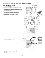
... to verify that it opens and closes fully. This entrance is for the second gate before proceeding to the gate with cable ties. INSTALLATION » SECURE GATE BRACKET TO GATE + WARNING SIGN PLACEMENT SECURE GATE BRACKET TO GATE The gate operator (arm) must use separate entrance Gate may require additional reinforcement be installed on both sides of the...
... to verify that it opens and closes fully. This entrance is for the second gate before proceeding to the gate with cable ties. INSTALLATION » SECURE GATE BRACKET TO GATE + WARNING SIGN PLACEMENT SECURE GATE BRACKET TO GATE The gate operator (arm) must use separate entrance Gate may require additional reinforcement be installed on both sides of the...

LA400 Manual
Page 19
... provided). Wall C. C. 18 Post B. Knock Outs B. INSTALLATION » STANDARD CONTROL BOX MOUNT THE CONTROL BOX The control box MUST be mounted within 5 feet (1.5 m) of the gate operator. A.
... provided). Wall C. C. 18 Post B. Knock Outs B. INSTALLATION » STANDARD CONTROL BOX MOUNT THE CONTROL BOX The control box MUST be mounted within 5 feet (1.5 m) of the gate operator. A.
LA400 Manual
Page 21
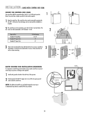
... and hammer. NOTE: The additional standoffs are specifically designed to mount up to the operator. 1 Install earth ground rod within 5 feet (1.5 m) of the gate operator. 1 90° Mount the control box as high as possible for 3 wall or column mounting. The control box door may be removed by opening...CLOSE LIMIT LEARN LIMITS aside CLOSE EDGE OPEN EDGE/ PHOTO OPEN PHOTO CLOSE PHOTO ACCESSORY POWER 12 V BR GR WH YL BL RD GATE 2 FORCE GATE 2 ON OFF AUTO OPEN LOW BATT OFF MAX SINGLE BUTTON TIMER TO CLOSE OPEN CONTROL INPUTS SINGLE BUTTON OFF MAX RESET STOP CTRL PWR...
... and hammer. NOTE: The additional standoffs are specifically designed to mount up to the operator. 1 Install earth ground rod within 5 feet (1.5 m) of the gate operator. 1 90° Mount the control box as high as possible for 3 wall or column mounting. The control box door may be removed by opening...CLOSE LIMIT LEARN LIMITS aside CLOSE EDGE OPEN EDGE/ PHOTO OPEN PHOTO CLOSE PHOTO ACCESSORY POWER 12 V BR GR WH YL BL RD GATE 2 FORCE GATE 2 ON OFF AUTO OPEN LOW BATT OFF MAX SINGLE BUTTON TIMER TO CLOSE OPEN CONTROL INPUTS SINGLE BUTTON OFF MAX RESET STOP CTRL PWR...

LA400 Manual
Page 22
... XMITTER ON OFF LOCK / BIPA RT DELAY CLOSE EDGE OPEN EDGE/ PHOTO OPEN PHOTO SET OPEN LIMIT GATE 1 CLOSE PHOTO SET CLOSE LIMIT LEARN LIMITS FORCE GATE 2 ON OFF AUTO OPEN LOW BATT OFF MAX SINGLE BUTTON TIMER TO CLOSE OPEN CONTROL INPUTS SINGLE BUTTON RESET OFF MAX ... 120 Vac ONLY The XLM control box wires the same as the standard control box. The second receptacle can be removed to power up additional gate operator accessories. Follow all instructions for the control board power supply. The illustrations show the standard control box, not the XLM control box. 21...
... XMITTER ON OFF LOCK / BIPA RT DELAY CLOSE EDGE OPEN EDGE/ PHOTO OPEN PHOTO SET OPEN LIMIT GATE 1 CLOSE PHOTO SET CLOSE LIMIT LEARN LIMITS FORCE GATE 2 ON OFF AUTO OPEN LOW BATT OFF MAX SINGLE BUTTON TIMER TO CLOSE OPEN CONTROL INPUTS SINGLE BUTTON RESET OFF MAX ... 120 Vac ONLY The XLM control box wires the same as the standard control box. The second receptacle can be removed to power up additional gate operator accessories. Follow all instructions for the control board power supply. The illustrations show the standard control box, not the XLM control box. 21...


