
LA400 Manual
Page 1
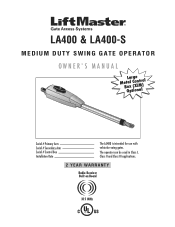
LA400 & LA400-S MEDIUM DUTY SWING GATE OPERATOR OWNER'S MANUAL MeBtOoLaaxplrtC(giXooennLMatrl)ol Serial # Primary Arm Serial # Secondary Arm Serial # Control Box Installation Date The LA400 is intended for use with vehicular swing gates. The operator can be used in Class I, Class II and Class III applications. 2 YEAR WARRANTY Radio Receiver Built on Board 315 MHz
LA400 & LA400-S MEDIUM DUTY SWING GATE OPERATOR OWNER'S MANUAL MeBtOoLaaxplrtC(giXooennLMatrl)ol Serial # Primary Arm Serial # Secondary Arm Serial # Control Box Installation Date The LA400 is intended for use with vehicular swing gates. The operator can be used in Class I, Class II and Class III applications. 2 YEAR WARRANTY Radio Receiver Built on Board 315 MHz

LA400 Manual
Page 2
... (XLM) WIRING Connect the Gate Operator (Gate 1) to the Control Box Set the Bipart Delay (Model LA400-S Only) Connect the Gate Operator (Gate 2) to the Control Box (Model LA400-S Only) Junction Box (Model LA400-S Only) Connect Transformer to Control Board Earth Ground Rod Installation (Optional) Connect Batteries 1-6 1 2 3...Release Maintenance TROUBLESHOOTING Basic Control Board Layout Wiring Diagram Diagnostic Codes Troubleshooting Chart REPAIR PARTS Control Box Gate Operator Arm How to Order Repair Parts WARRANTY POLICY ACCESSORIES TEMPLATE SAFETY » SAFETY SYMBOL AND SIGNAL WORD REVIEW ...
... (XLM) WIRING Connect the Gate Operator (Gate 1) to the Control Box Set the Bipart Delay (Model LA400-S Only) Connect the Gate Operator (Gate 2) to the Control Box (Model LA400-S Only) Junction Box (Model LA400-S Only) Connect Transformer to Control Board Earth Ground Rod Installation (Optional) Connect Batteries 1-6 1 2 3...Release Maintenance TROUBLESHOOTING Basic Control Board Layout Wiring Diagram Diagnostic Codes Troubleshooting Chart REPAIR PARTS Control Box Gate Operator Arm How to Order Repair Parts WARRANTY POLICY ACCESSORIES TEMPLATE SAFETY » SAFETY SYMBOL AND SIGNAL WORD REVIEW ...

LA400 Manual
Page 3
... of the following as a factory or loading dock area or other building servicing the general public. SAFETY ACCESSORY SELECTION All UL325 compliant LiftMaster gate operators will accept external entrapment protection devices to protect people from motorized gate systems. UL325 requires that the installation must have one ... that the type of contact with a solid object. SAFETY » UL325 MODEL CLASSIFICATIONS CLASS I CLASS II CLASS III Swing & Gate Barrier (Arm) Operator Primary Type A A, B1 or B2 Secondary Type A, B1 or B2 A, B1, B2 or E The chart above . CLASS III -
... of the following as a factory or loading dock area or other building servicing the general public. SAFETY ACCESSORY SELECTION All UL325 compliant LiftMaster gate operators will accept external entrapment protection devices to protect people from motorized gate systems. UL325 requires that the installation must have one ... that the type of contact with a solid object. SAFETY » UL325 MODEL CLASSIFICATIONS CLASS I CLASS II CLASS III Swing & Gate Barrier (Arm) Operator Primary Type A A, B1 or B2 Secondary Type A, B1 or B2 A, B1, B2 or E The chart above . CLASS III -

LA400 Manual
Page 4
... open position. f. Install the gate operator only when: a. Locate the gate such that transmits radio frequency (RF) signals to reduce the risk of a vertical barrier (arm). 3 b. The pedestrian access opening and closing to the gate operator for vehicles. Gate systems are eliminated or guarded, and guarding is greater than 6 inches (152...
... open position. f. Install the gate operator only when: a. Locate the gate such that transmits radio frequency (RF) signals to reduce the risk of a vertical barrier (arm). 3 b. The pedestrian access opening and closing to the gate operator for vehicles. Gate systems are eliminated or guarded, and guarding is greater than 6 inches (152...

LA400 Manual
Page 8
Six Conductor, 9 feet (2.7 m) • Warning Sign (2) • Battery (2) • Plug-in Transformer (1) LA400-S (SECOND GATE OPERATOR ARM) • Motor Cable - INTRODUCTION » OPERATOR SPECIFICATIONS + CARTON INVENTORY OPERATOR SPECIFICATIONS Operating Cycles: Main Supply (Motor): Current Consumption: Power Consumption: Battery Charger Supply: Maximum Gate ....4" (95 cm) 53.5" (136 cm) CARTON INVENTORY Carton inventory is doubled except for control box. • Standard Control Box (1) • Hardware Bag (1) • Gate Operator Arm • Motor Cable -
Six Conductor, 9 feet (2.7 m) • Warning Sign (2) • Battery (2) • Plug-in Transformer (1) LA400-S (SECOND GATE OPERATOR ARM) • Motor Cable - INTRODUCTION » OPERATOR SPECIFICATIONS + CARTON INVENTORY OPERATOR SPECIFICATIONS Operating Cycles: Main Supply (Motor): Current Consumption: Power Consumption: Battery Charger Supply: Maximum Gate ....4" (95 cm) 53.5" (136 cm) CARTON INVENTORY Carton inventory is doubled except for control box. • Standard Control Box (1) • Hardware Bag (1) • Gate Operator Arm • Motor Cable -
LA400 Manual
Page 12
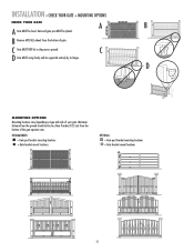
... GATE + MOUNTING OPTIONS CHECK YOUR GATE A B A Gate MUST be supported entirely by its hinges. B Remove ANY/ALL wheels from the bottom of the gate operator arm. D MOUNTING OPTIONS Mounting locations vary depending on type and style of gate. C D Gate MUST swing freely and be level. Minimum distance from the ground should...
... GATE + MOUNTING OPTIONS CHECK YOUR GATE A B A Gate MUST be supported entirely by its hinges. B Remove ANY/ALL wheels from the bottom of the gate operator arm. D MOUNTING OPTIONS Mounting locations vary depending on type and style of gate. C D Gate MUST swing freely and be level. Minimum distance from the ground should...
LA400 Manual
Page 16
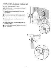
... on gate for mounting options. 1 Open the gate to desired open position (no greater than 100°) and hold operator against gate. 2 Place the operator arm against gate post at the desired position. Temporarily secure gate post bracket with washer, lock washer and nut. 1 3 4 7" (18 cm) 7" (18 cm) Hex Bolt 3/8" 5 Washer...
... on gate for mounting options. 1 Open the gate to desired open position (no greater than 100°) and hold operator against gate. 2 Place the operator arm against gate post at the desired position. Temporarily secure gate post bracket with washer, lock washer and nut. 1 3 4 7" (18 cm) 7" (18 cm) Hex Bolt 3/8" 5 Washer...
LA400 Manual
Page 17
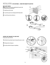
... holes in the gate post. 3 Secure the post bracket to fully extend or fully retract. 1/2" (1.3 cm) SECURE POST BRACKET TO GATE POST The gate operator (arm) must be level. 1 Mark holes for the post bracket. Flat Washers 3 Hex Nuts Lock Washers 16 2 Carriage Bolts Welder (Optional) INSTALLATION » TEST GATE TRAVEL...
... holes in the gate post. 3 Secure the post bracket to fully extend or fully retract. 1/2" (1.3 cm) SECURE POST BRACKET TO GATE POST The gate operator (arm) must be level. 1 Mark holes for the post bracket. Flat Washers 3 Hex Nuts Lock Washers 16 2 Carriage Bolts Welder (Optional) INSTALLATION » TEST GATE TRAVEL...
LA400 Manual
Page 18
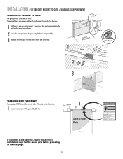
... necessary) that it opens and closes fully. INSTALLATION » SECURE GATE BRACKET TO GATE + WARNING SIGN PLACEMENT SECURE GATE BRACKET TO GATE The gate operator (arm) must use separate entrance Some installations may move the gate to the gate with cable ties. This entrance is for the second gate before proceeding...
... necessary) that it opens and closes fully. INSTALLATION » SECURE GATE BRACKET TO GATE + WARNING SIGN PLACEMENT SECURE GATE BRACKET TO GATE The gate operator (arm) must use separate entrance Some installations may move the gate to the gate with cable ties. This entrance is for the second gate before proceeding...
LA400 Manual
Page 31
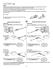
...gate is in the desired closed position, SET press the LEARN LIMITS button again. If a mistake is made during the installation process. SINGLE ARM LEFT-HAND SIDE PROGRAM OPEN 3 Press the LEARN LIMITS button (SET OPEN LIMIT LED will beep. LEARN LIMITS button SET OPEN LIMIT OFF...position. DIAGNOSTIC GATE 1 SET CLOSE 7 When gate is mounted and how many operators the installation includes. DIAGNOSTIC GATE 1 SET CLOSE OR SINGLE ARM RIGHT-HAND SIDE PROGRAM OPEN 3 Press the LEARN LIMITS button (SET OPEN LIMIT LED will beep. The programming uses a combination of the gate...
...gate is in the desired closed position, SET press the LEARN LIMITS button again. If a mistake is made during the installation process. SINGLE ARM LEFT-HAND SIDE PROGRAM OPEN 3 Press the LEARN LIMITS button (SET OPEN LIMIT LED will beep. LEARN LIMITS button SET OPEN LIMIT OFF...position. DIAGNOSTIC GATE 1 SET CLOSE 7 When gate is mounted and how many operators the installation includes. DIAGNOSTIC GATE 1 SET CLOSE OR SINGLE ARM RIGHT-HAND SIDE PROGRAM OPEN 3 Press the LEARN LIMITS button (SET OPEN LIMIT LED will beep. The programming uses a combination of the gate...
LA400 Manual
Page 43
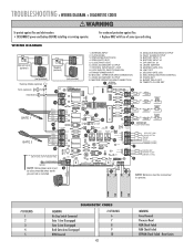
CONTROL INPUTS/EXIT LOOP 8. LOOP INPUTS, SAFETY/SHADOW 9. SECOND - BATTERY INPUT #1 16. CLOSE EDGE 3. OPERATOR ARM CONNECTION 11. 24VDC ACCESSORY OUTPUT 12. BATTERY INPUT #2 17. FORCE SET 24. MAGLOCK/SOLENOID OUTPUT 14. FAULT ALARM OUTPUT 15.... 15 NOTE: Batteries must be connected to operate. # OF BLINKS 1 2 3 4 5 DIAGNOSTIC CODES MEANING No Stop Switch Connected Gate 1 Arm Disengaged Gate 2 Arm Disengaged Both Gate Arms Disengaged RPM Reversal # OF BLINKS 6 7 8 9 10 42 MEANING Force Reversal Processor Reset ROM Check Failed RAM Check Failed EEPROM Check Failed ...
CONTROL INPUTS/EXIT LOOP 8. LOOP INPUTS, SAFETY/SHADOW 9. SECOND - BATTERY INPUT #1 16. CLOSE EDGE 3. OPERATOR ARM CONNECTION 11. 24VDC ACCESSORY OUTPUT 12. BATTERY INPUT #2 17. FORCE SET 24. MAGLOCK/SOLENOID OUTPUT 14. FAULT ALARM OUTPUT 15.... 15 NOTE: Batteries must be connected to operate. # OF BLINKS 1 2 3 4 5 DIAGNOSTIC CODES MEANING No Stop Switch Connected Gate 1 Arm Disengaged Gate 2 Arm Disengaged Both Gate Arms Disengaged RPM Reversal # OF BLINKS 6 7 8 9 10 42 MEANING Force Reversal Processor Reset ROM Check Failed RAM Check Failed EEPROM Check Failed ...

LA400 Manual
Page 44
...control board. Connect batteries. Move accessories to -Close section for obstruction on control board to resume normal operation. Check proper installation of operator arm. GATE STOPS AND REVERSES (Force Reversal) RPM REVERSAL POSSIBLE CAUSE 1) No voltage to board. 2) Bad control board. 1) Low/disconnected ... to Open Only command. 1) Battery Low >23.5 V 1) Bipart Delay not set too low. 3) Bad gate hardware. 4) Incorrect Arm installation. 1) Obstructed Arm (bottoms out). 2) Bad RPM Sensor. 3) Too much mA pulled off board. GATE OPENS BUT DOES NOT CLOSE Audible beeps (3 times...
...control board. Connect batteries. Move accessories to -Close section for obstruction on control board to resume normal operation. Check proper installation of operator arm. GATE STOPS AND REVERSES (Force Reversal) RPM REVERSAL POSSIBLE CAUSE 1) No voltage to board. 2) Bad control board. 1) Low/disconnected ... to Open Only command. 1) Battery Low >23.5 V 1) Bipart Delay not set too low. 3) Bad gate hardware. 4) Incorrect Arm installation. 1) Obstructed Arm (bottoms out). 2) Bad RPM Sensor. 3) Too much mA pulled off board. GATE OPENS BUT DOES NOT CLOSE Audible beeps (3 times...

LA400 Manual
Page 45
REPAIR PARTS » CONTROL BOX + GATE OPERATOR ARM CONTROL BOX Refer to the parts lists below for replacement parts available for your operator, certain components may be added or removed from these lists. ... Kit Includes 20 Amp (1), 15 Amp (2) Receiver Module - 390 MHz Receiver Module - 315 MHz Reset Switch (XLM Control Box) Alarm (XLM Control Box) GATE OPERATOR ARM 22 33 ITEM PART # DESCRIPTION QTY 1 41ASWG-442SA Release Lever 1 2 41ASWG-438SA Motor with Limit 1 11 Switch Harness 3 41ASWG-0014SA Rear Connector 1 4 41ASWG-489 Cable...
REPAIR PARTS » CONTROL BOX + GATE OPERATOR ARM CONTROL BOX Refer to the parts lists below for replacement parts available for your operator, certain components may be added or removed from these lists. ... Kit Includes 20 Amp (1), 15 Amp (2) Receiver Module - 390 MHz Receiver Module - 315 MHz Reset Switch (XLM Control Box) Alarm (XLM Control Box) GATE OPERATOR ARM 22 33 ITEM PART # DESCRIPTION QTY 1 41ASWG-442SA Release Lever 1 2 41ASWG-438SA Motor with Limit 1 11 Switch Harness 3 41ASWG-0014SA Rear Connector 1 4 41ASWG-489 Cable...
LA400 Pull to Open Addendum Manual
Page 2
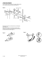
Move the gate manually to brackets with c-clamps. All Rights Reserved ATTACH THE OPERATOR Secure brackets to post and gate with pins and clips provided (Figure 2). Attach operator arm to the fully open and fully closed positions. It is extremely important that the gate bracket does not bind with the post bracket (Figure 4). Figure 3 Figure 4 01-33464 ©2006, The Chamberlain Group, Inc. Figure 2 Operator must be level C-Clamp Actuator Side Pin Gate Bracket Hairpin Clip C-Clamp Disengage the operator by inserting the key and rotating the handle (Figure 3).
Move the gate manually to brackets with c-clamps. All Rights Reserved ATTACH THE OPERATOR Secure brackets to post and gate with pins and clips provided (Figure 2). Attach operator arm to the fully open and fully closed positions. It is extremely important that the gate bracket does not bind with the post bracket (Figure 4). Figure 3 Figure 4 01-33464 ©2006, The Chamberlain Group, Inc. Figure 2 Operator must be level C-Clamp Actuator Side Pin Gate Bracket Hairpin Clip C-Clamp Disengage the operator by inserting the key and rotating the handle (Figure 3).


