

LA400 Manual
Page 10
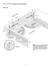
...Sign Gate Bracket tTpiPKDlehoEaimdyMsEeneiPeosonwttnirCvtlttiriLehIhataeEonnnncsuAgjctghaiRelt!umpiedrrusirGGsaofeyatrratoneteruaowos.vearepmereashnriiyCeaDcntlpaegmeea.rtsonaavhttoeeenClhagetyaanttauernasyonrece Hinge Post Bracket Operator Operator Cable Antenna Control Box with Batteries Hinge Post Bracket Gate Bracket PVC Conduit (not ...sensor while the gate is still moving. INSTALLATION » OVERVIEW OF TYPICAL INSTALLATION LEFT-HAND GATE Warning Sign Antenna Control Box with Batteries Photoelectric Sensors 12 Gauge Wire PVC Conduit (not provided) to reduce the risk of...
...Sign Gate Bracket tTpiPKDlehoEaimdyMsEeneiPeosonwttnirCvtlttiriLehIhataeEonnnncsuAgjctghaiRelt!umpiedrrusirGGsaofeyatrratoneteruaowos.vearepmereashnriiyCeaDcntlpaegmeea.rtsonaavhttoeeenClhagetyaanttauernasyonrece Hinge Post Bracket Operator Operator Cable Antenna Control Box with Batteries Hinge Post Bracket Gate Bracket PVC Conduit (not ...sensor while the gate is still moving. INSTALLATION » OVERVIEW OF TYPICAL INSTALLATION LEFT-HAND GATE Warning Sign Antenna Control Box with Batteries Photoelectric Sensors 12 Gauge Wire PVC Conduit (not provided) to reduce the risk of...
LA400 Manual
Page 11
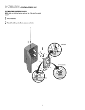
... be exercised to protect the low voltage wire from lawn mowers and string trimmers. INSTALLATION » OVERVIEW OF TYPICAL INSTALLATION DUAL GATE Warning Sign Hinge Antenna Post Bracket Gate Bracket Gate 1 Control Box with Batteries Operator Cable Gate 2 Junction Box Extension Cable Photoelectric Sensors PVC Conduit (not provided) to reduce the...
... be exercised to protect the low voltage wire from lawn mowers and string trimmers. INSTALLATION » OVERVIEW OF TYPICAL INSTALLATION DUAL GATE Warning Sign Hinge Antenna Post Bracket Gate Bracket Gate 1 Control Box with Batteries Operator Cable Gate 2 Junction Box Extension Cable Photoelectric Sensors PVC Conduit (not provided) to reduce the...
LA400 Manual
Page 20
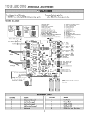
INSTALLATION » STANDARD CONTROL BOX INSTALL THE CONTROL BOARD NOTE: Make sure the battery leads are on the left side of the control box and not pinched. 1 Attach the antenna. 2 Reinstall the batteries, control board, alarm and reset button. 1 2 Coaxial Connector Reset Button Connections Alarm 19
INSTALLATION » STANDARD CONTROL BOX INSTALL THE CONTROL BOARD NOTE: Make sure the battery leads are on the left side of the control box and not pinched. 1 Attach the antenna. 2 Reinstall the batteries, control board, alarm and reset button. 1 2 Coaxial Connector Reset Button Connections Alarm 19

LA400 Manual
Page 42
... 4 Connector P7 5 Connector P9 6 Connector P12 7 Connector P10 8 Connector P11 9 Connector P5 10 Connector P16 11 Connector P13 12 Connector P17 13 Connector P14 FUNCTION Antenna Input Close Edge Open Edge/Photo Open Photo Close Photo Switched Accessory Power* Control Inputs Loop Inputs 24 Vac Input Gate 2 Accessory Power* Gate 1 Maglock...
... 4 Connector P7 5 Connector P9 6 Connector P12 7 Connector P10 8 Connector P11 9 Connector P5 10 Connector P16 11 Connector P13 12 Connector P17 13 Connector P14 FUNCTION Antenna Input Close Edge Open Edge/Photo Open Photo Close Photo Switched Accessory Power* Control Inputs Loop Inputs 24 Vac Input Gate 2 Accessory Power* Gate 1 Maglock...
LA400 Manual
Page 43
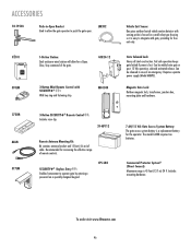
.... CLOSE PHOTO EYE 6. 24VDC ACCESSORY OUTPUT 7. LOOP INPUTS, SAFETY/SHADOW 9. FAULT ALARM OUTPUT 15. SECOND GATE JOG 22. TRANSFORMER INPUT 10. MASTER OPERATOR ARM CONNECTION 1 ANTENNA CONNECTION 13. LEARN XMITTER 19. Reset Limits WIRING DIAGRAM Solenoid Lock (optional) MAGLOCK NO C NC Maglock (optional) MAGLOCK NO C NC (not provided) Flashing Strobe (optional...
.... CLOSE PHOTO EYE 6. 24VDC ACCESSORY OUTPUT 7. LOOP INPUTS, SAFETY/SHADOW 9. FAULT ALARM OUTPUT 15. SECOND GATE JOG 22. TRANSFORMER INPUT 10. MASTER OPERATOR ARM CONNECTION 1 ANTENNA CONNECTION 13. LEARN XMITTER 19. Reset Limits WIRING DIAGRAM Solenoid Lock (optional) MAGLOCK NO C NC Maglock (optional) MAGLOCK NO C NC (not provided) Flashing Strobe (optional...

LA400 Manual
Page 45
...-30763 8 K76-19446 K74-30941 K001A5747-2 K001A5747 K76-35600 K76-35364 DESCRIPTION QTY Control Board 1 Control Box & Cover with Gasket 1 Control Board Bracket 1 Reset Switch 1 Antenna 1 Battery 2 Transformer 1 Alarm 1 Not Shown ATC Fuse Kit Includes 20 Amp (1), 15 Amp (2) Receiver Module - 390 MHz Receiver Module - 315 MHz Reset Switch (XLM Control...
...-30763 8 K76-19446 K74-30941 K001A5747-2 K001A5747 K76-35600 K76-35364 DESCRIPTION QTY Control Board 1 Control Box & Cover with Gasket 1 Control Board Bracket 1 Reset Switch 1 Antenna 1 Battery 2 Transformer 1 Alarm 1 Not Shown ATC Fuse Kit Includes 20 Amp (1), 15 Amp (2) Receiver Module - 390 MHz Receiver Module - 315 MHz Reset Switch (XLM Control...
LA400 Manual
Page 47
...open. Requires separate power supply (Model ARMP5). To order visit www.liftmaster.com 46 Fail safe operation keeps gate locked if power is 45 feet (13.7 m) 24 V. The model LA400 requires two batteries. ACCESSORIES 50-19503 Push-to-Open Bracket Used ... mounting plate and hardware. 373LM 86LM 377LM 3-Button SECURITY✚®OPENRemote Control : Includes visor clip. 29-NP712 Remote Antenna Mounting Kit: Kit contains antenna bracket and 15 feet (4.6 m) of an emergency. Includes mounting hardware. Commercial Protector System® (Direct Connect): Maximum range...
...open. Requires separate power supply (Model ARMP5). To order visit www.liftmaster.com 46 Fail safe operation keeps gate locked if power is 45 feet (13.7 m) 24 V. The model LA400 requires two batteries. ACCESSORIES 50-19503 Push-to-Open Bracket Used ... mounting plate and hardware. 373LM 86LM 377LM 3-Button SECURITY✚®OPENRemote Control : Includes visor clip. 29-NP712 Remote Antenna Mounting Kit: Kit contains antenna bracket and 15 feet (4.6 m) of an emergency. Includes mounting hardware. Commercial Protector System® (Direct Connect): Maximum range...


