HS670 GL BOARD Manual
Page 1
GLCONTROLLER BOARD MODEL HS670 HEAVY DUTY HYDRAULIC SLIDE GATE OPERATOR 2 YEAR WARRANTY Serial located on electrical box cover) Installation Date MODEL HS670 IS FOR VEHICULAR PASSAGE GATES ONLY AND IS NOT INTENDED FOR PEDESTRIAN PASSAGE GATE USE
GLCONTROLLER BOARD MODEL HS670 HEAVY DUTY HYDRAULIC SLIDE GATE OPERATOR 2 YEAR WARRANTY Serial located on electrical box cover) Installation Date MODEL HS670 IS FOR VEHICULAR PASSAGE GATES ONLY AND IS NOT INTENDED FOR PEDESTRIAN PASSAGE GATE USE
HS670 GL BOARD Manual
Page 2
...installation check that all safety instructions. • DO NOT attempt repair or service of your gate and/or the gate Operator Notes 35 AVERTISSEMENT Repair Parts and Service 36 ATTENTION operator if you do not comply with the cautionary statements that accompany it will Warranty Policy 34 ...alert you to the possibility of damage to your commercial door and gate operator unless you are an Authorized Service Technician. Read the warnings Electrical Box 32 carefully. The hazard may come from REPAIR PARTS...
...installation check that all safety instructions. • DO NOT attempt repair or service of your gate and/or the gate Operator Notes 35 AVERTISSEMENT Repair Parts and Service 36 ATTENTION operator if you do not comply with the cautionary statements that accompany it will Warranty Policy 34 ...alert you to the possibility of damage to your commercial door and gate operator unless you are an Authorized Service Technician. Read the warnings Electrical Box 32 carefully. The hazard may come from REPAIR PARTS...

HS670 GL BOARD Manual
Page 3
.... It incorporates 2 solenoids which are oil tight and watertight, and of the gate. HYDRAULIC BRAKE Dual valve system limits gate over travel. BYPASS VALVE Incorporates a handle at 600 p.s.i. F. DRIVE WHEELS Drive wheels are T.E.F.C. (totally enclosed, fan cooled) and operate at 3450 R.P.M. J. K. D. HS670 2HP= 2" wide, 6" diameter. B. for left hand. H. HYDRAULIC MOTOR Roller vane, free wheeling...
.... It incorporates 2 solenoids which are oil tight and watertight, and of the gate. HYDRAULIC BRAKE Dual valve system limits gate over travel. BYPASS VALVE Incorporates a handle at 600 p.s.i. F. DRIVE WHEELS Drive wheels are T.E.F.C. (totally enclosed, fan cooled) and operate at 3450 R.P.M. J. K. D. HS670 2HP= 2" wide, 6" diameter. B. for left hand. H. HYDRAULIC MOTOR Roller vane, free wheeling...

HS670 GL BOARD Manual
Page 4
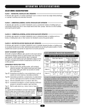
Maximum Gate Weight - 3000 lbs. MODEL HS670 GI • 1 HP Motor Gate Speed - 18"/sec. Maximum Gate Weight - 3000 lbs. Maximum Gate Weight - 5000 lbs. MODEL HS670 GI • 2 HP Motor Gate Speed - 18"/sec. Maximum V-Track Gate Width - 80 ft. Maximum V-Track Gate Width - 80 ft. 27" 19-3/4" 29-3/4" 31-3/4" 14" 26-1/2" 4 Maximum V-Track Gate Width - 80 ft. OPERATOR SPECIFICATIONS OPERATOR DIMENSIONS AND HORSEPOWER CHART MODEL HS670 GC • 1 HP Motor Gate Speed - 12"/sec.
Maximum Gate Weight - 3000 lbs. MODEL HS670 GI • 1 HP Motor Gate Speed - 18"/sec. Maximum Gate Weight - 3000 lbs. Maximum Gate Weight - 5000 lbs. MODEL HS670 GI • 2 HP Motor Gate Speed - 18"/sec. Maximum V-Track Gate Width - 80 ft. Maximum V-Track Gate Width - 80 ft. 27" 19-3/4" 29-3/4" 31-3/4" 14" 26-1/2" 4 Maximum V-Track Gate Width - 80 ft. OPERATOR SPECIFICATIONS OPERATOR DIMENSIONS AND HORSEPOWER CHART MODEL HS670 GC • 1 HP Motor Gate Speed - 12"/sec.
HS670 GL BOARD Manual
Page 5
... All UL325 compliant LiftMaster gate operators will accept external entrapment protection devices to operate the operator open and close . That means that all installations must satisfy the entrapment protection chart shown above. Both primary and secondary entrapment protection methods must have warning signs placed in a home of one of motorized gate systems. Model HS670 meets the following...
... All UL325 compliant LiftMaster gate operators will accept external entrapment protection devices to operate the operator open and close . That means that all installations must satisfy the entrapment protection chart shown above. Both primary and secondary entrapment protection methods must have warning signs placed in a home of one of motorized gate systems. Model HS670 meets the following...
HS670 GL BOARD Manual
Page 6
...force in the line-of-sight of a vertical barrier (arm). 6 The operator is specifically designed for exposed rollers. 5. The gate must reduce public exposure to the gate operator for entrapment protection functions shall be located where the risk of entrapment or obstruction ... leading edge of a vehicular horizontal slide gate. Gate systems design and installation must be located at any moving . Install the gate operator only when: a. b. For a gate operator utilizing a contact sensor such as when a vehicle trips the sensor while the gate is not subject to start. 10....
...force in the line-of-sight of a vertical barrier (arm). 6 The operator is specifically designed for exposed rollers. 5. The gate must reduce public exposure to the gate operator for entrapment protection functions shall be located where the risk of entrapment or obstruction ... leading edge of a vehicular horizontal slide gate. Gate systems design and installation must be located at any moving . Install the gate operator only when: a. b. For a gate operator utilizing a contact sensor such as when a vehicle trips the sensor while the gate is not subject to start. 10....

HS670 GL BOARD Manual
Page 7
OPERATOR WARNINGS SUGGESTED ENTRAPMENT PROTECTION DEVICE LOCATIONS GATE SYSTEM (COMMERCIAL SLIDE GATE) Sentex Telephone Entry System/Access Control Open Edge Close Edge Photo Eye For Open Cycle STREET 4' Typical 8' Interrupt Loop Photo Eye For Close Cycle 4' Typical 4' ... COMPLEX OR PARKING LOT Run Twisted Wire * From Loop To Detector Seal Loops * 1-1/2" Loop Wire Layer * 1/4" Or As Required For Loop Wire Width GATE SYSTEM (MASTER/SECOND SLIDE GATE) Open Edge Second Unit Open Edge STREET Photo Eye For Close Cycle Photo Eye For Open Cycle Master Unit Photo Eye For Open...
OPERATOR WARNINGS SUGGESTED ENTRAPMENT PROTECTION DEVICE LOCATIONS GATE SYSTEM (COMMERCIAL SLIDE GATE) Sentex Telephone Entry System/Access Control Open Edge Close Edge Photo Eye For Open Cycle STREET 4' Typical 8' Interrupt Loop Photo Eye For Close Cycle 4' Typical 4' ... COMPLEX OR PARKING LOT Run Twisted Wire * From Loop To Detector Seal Loops * 1-1/2" Loop Wire Layer * 1/4" Or As Required For Loop Wire Width GATE SYSTEM (MASTER/SECOND SLIDE GATE) Open Edge Second Unit Open Edge STREET Photo Eye For Close Cycle Photo Eye For Open Cycle Master Unit Photo Eye For Open...

HS670 GL BOARD Manual
Page 8
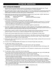
...Sides of the Exposed Rollers Can Prevent Hands From Reaching These Pinch-Points Open Gate Edge Open Gate Edge Gate Edge for refitting of these rollers from the gate or any time without prior warning. This operator is not a chance of INJURY at least 6' ATTENTION from many fence ... fence. NOT FOR USE AS PEDESTRIAN PASSAGE! This entrance is for vehicular use separate entrance AVERTISSEMENT OPERATOR WARNINGS SAFETY PRECAUTIONS FOR OPEN ROLLER GATES AND ORNAMENT "GRILL TYPE" GATES WARNING • Injuries occur when people get their arm and it gets caught between the top ...
...Sides of the Exposed Rollers Can Prevent Hands From Reaching These Pinch-Points Open Gate Edge Open Gate Edge Gate Edge for refitting of these rollers from the gate or any time without prior warning. This operator is not a chance of INJURY at least 6' ATTENTION from many fence ... fence. NOT FOR USE AS PEDESTRIAN PASSAGE! This entrance is for vehicular use separate entrance AVERTISSEMENT OPERATOR WARNINGS SAFETY PRECAUTIONS FOR OPEN ROLLER GATES AND ORNAMENT "GRILL TYPE" GATES WARNING • Injuries occur when people get their arm and it gets caught between the top ...

HS670 GL BOARD Manual
Page 9
...means of fastening as shown. IMPORTANT NOTE: Make sure that secure the mounting legs to the unit. Lift cover off. 2. Secure operator to the gate and operator. 2. After adjustment, retighten the bolts. Left-handed is opposite. The pad must be level and parallel with the drive wheels facing...above the ground line. Conduit locations may want to install drive rail 11-1/2" from the front of the cover. The operator must be the gate opening when inside looking out). For left-handed conversion, see instructions provided with it. Layout concrete pad as required, prior...
...means of fastening as shown. IMPORTANT NOTE: Make sure that secure the mounting legs to the unit. Lift cover off. 2. Secure operator to the gate and operator. 2. After adjustment, retighten the bolts. Left-handed is opposite. The pad must be level and parallel with the drive wheels facing...above the ground line. Conduit locations may want to install drive rail 11-1/2" from the front of the cover. The operator must be the gate opening when inside looking out). For left-handed conversion, see instructions provided with it. Layout concrete pad as required, prior...
HS670 GL BOARD Manual
Page 10
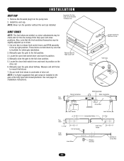
NOTE: Never run the operator without the vent cap installed. These items are slotted, so minor adjustments may be made later for initial gate installation. 2. Locate the close position. 5. Remove Bolt To Take Cover Off Loosen Screw To Remove Cover Threaded Plug Vent Cap Tank Top ...positions. Manually open limit switch lever and mark its position on the drive rail. 6. I N S TA L L AT I O N VENT CAP 1. Manually close the gate to the gate at the fully open and close positions. Secure both limit shoes to mount limit shoes 7. Install the vent cap. Important: Do Not Use Cover...
NOTE: Never run the operator without the vent cap installed. These items are slotted, so minor adjustments may be made later for initial gate installation. 2. Locate the close position. 5. Remove Bolt To Take Cover Off Loosen Screw To Remove Cover Threaded Plug Vent Cap Tank Top ...positions. Manually open limit switch lever and mark its position on the drive rail. 6. I N S TA L L AT I O N VENT CAP 1. Manually close the gate to the gate at the fully open and close positions. Secure both limit shoes to mount limit shoes 7. Install the vent cap. Important: Do Not Use Cover...

HS670 GL BOARD Manual
Page 11
... 1. NOTE: It is the suspension separator bolt. This system puts pressure on the drive rail. By positioning the valve handle down (manual operation), the gate can not interfere with LiftMaster Drive Rail) Upper Drive Wheel Drive Rail Guide Wheel Lower Drive Wheel Bypass Valve Handle In Automatic Position Rotate 90° (Down) For...
... 1. NOTE: It is the suspension separator bolt. This system puts pressure on the drive rail. By positioning the valve handle down (manual operation), the gate can not interfere with LiftMaster Drive Rail) Upper Drive Wheel Drive Rail Guide Wheel Lower Drive Wheel Bypass Valve Handle In Automatic Position Rotate 90° (Down) For...

HS670 GL BOARD Manual
Page 12
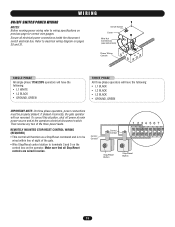
... installing power wiring or control stations be protected. ON POWER WIRING INSTALLATION Wiring Specifications (STRANDED COPPER WIRE) AVERTISSEMENT On a Dual Gate System, each unit must be dedicated and protected. power switch. The location of primary power disconnect should be installed on a dedicated...well MUST be cleared and secured, at the fuse box BEFORE proceeding. • ALL power and control wiring MUST be run the operator • ANY maintenance to persons and/or EMENTindividual. Failure • ALL electrical connections MUST be labeled. 12 WIRE GAUGE 6 ...
... installing power wiring or control stations be protected. ON POWER WIRING INSTALLATION Wiring Specifications (STRANDED COPPER WIRE) AVERTISSEMENT On a Dual Gate System, each unit must be dedicated and protected. power switch. The location of primary power disconnect should be installed on a dedicated...well MUST be cleared and secured, at the fuse box BEFORE proceeding. • ALL power and control wiring MUST be run the operator • ANY maintenance to persons and/or EMENTindividual. Failure • ALL electrical connections MUST be labeled. 12 WIRE GAUGE 6 ...
HS670 GL BOARD Manual
Page 13
...will function as a Stop/Reset command and is to electrical wiring diagram on the operator. Secure all Stop/Reset controls are wired in series. Refer to be properly phased. If phased incorrectly, the gate operator will have the following : • L1 WHITE • L2 BLACK •... GROUND, GREEN THREE PHASE All three phase operators will run reversed. Control Conduit Control Conduit Stop/Reset Button 1 234 567 ...
...will function as a Stop/Reset command and is to electrical wiring diagram on the operator. Secure all Stop/Reset controls are wired in series. Refer to be properly phased. If phased incorrectly, the gate operator will have the following : • L1 WHITE • L2 BLACK •... GROUND, GREEN THREE PHASE All three phase operators will run reversed. Control Conduit Control Conduit Stop/Reset Button 1 234 567 ...
HS670 GL BOARD Manual
Page 17
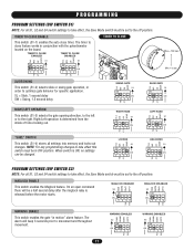
... close timer. SL = Slide, 1 second delay SW = Swing, 1.5 second delay TTC SW RT SWING GATE S1 ON ON 1 2 34 SAVE TTC SW RT SLIDE GATE S1 ON ON 1 2 34 SAVE LT SL LT SL RIGHT/LEFT OPERATION This switch (S1-3) selects the gate opening direction, to the left or to the right. Right/Left... ON 1 2 34 ON 1 2 34 TIMER TO CLOSE Max = 180 sec Min = 0 sec LT SL LT SL SLIDE/SWING This switch (S1-2) selects slide or swing gate operation, in OFF position. TTC TTC SW SL SW RT LT RT RIGHT HAND S1 ON ON 1 2 34 LOCKED S1 ON APEMs ON 1 2 34 SAVE SAVE...
... close timer. SL = Slide, 1 second delay SW = Swing, 1.5 second delay TTC SW RT SWING GATE S1 ON ON 1 2 34 SAVE TTC SW RT SLIDE GATE S1 ON ON 1 2 34 SAVE LT SL LT SL RIGHT/LEFT OPERATION This switch (S1-3) selects the gate opening direction, to the left or to the right. Right/Left... ON 1 2 34 ON 1 2 34 TIMER TO CLOSE Max = 180 sec Min = 0 sec LT SL LT SL SLIDE/SWING This switch (S1-2) selects slide or swing gate operation, in OFF position. TTC TTC SW SL SW RT LT RT RIGHT HAND S1 ON ON 1 2 34 LOCKED S1 ON APEMs ON 1 2 34 SAVE SAVE...
HS670 GL BOARD Manual
Page 19
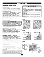
... Section below to reprogram the receiver for each remote control transmitter in use of CAUTION CONSTANT OPERATION on the hand-held remote that will be used to operate the gate operator. The receiver is factory set at HIGH. The receiver is factory set at the NORMAL mode...as the radio continues transmitting (Figure 2). Re-connect power to operate your gate operator. Repeat Steps 2 and 3 for 30 seconds. 3. NEVER permit children to operate, or play with remote control transmitters. • Activate gate or door ONLY when it overrides the safety reversal devices. ...
... Section below to reprogram the receiver for each remote control transmitter in use of CAUTION CONSTANT OPERATION on the hand-held remote that will be used to operate the gate operator. The receiver is factory set at HIGH. The receiver is factory set at the NORMAL mode...as the radio continues transmitting (Figure 2). Re-connect power to operate your gate operator. Repeat Steps 2 and 3 for 30 seconds. 3. NEVER permit children to operate, or play with remote control transmitters. • Activate gate or door ONLY when it overrides the safety reversal devices. ...
HS670 GL BOARD Manual
Page 20
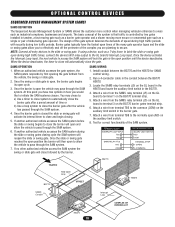
... vehicles access the SAM system the swing or slide gate will close and begin closing cycle the SAM system will lock the gate in the conduit between the BG770 and the HS670 for correct functionality of the many gate operator types and the slide or swing gates allow the vehicle to pass through the SAM system...
... vehicles access the SAM system the swing or slide gate will close and begin closing cycle the SAM system will lock the gate in the conduit between the BG770 and the HS670 for correct functionality of the many gate operator types and the slide or swing gates allow the vehicle to pass through the SAM system...

HS670 GL BOARD Manual
Page 21
...56 Terminals 3 & 5 (Com) - NOTE: Will not override a double entrapment (signalled by activating the transmitter when the gate is closed circuit and the operator will reset the timer to override a failed accessory such as a loop detector or photo-eye. A momentary activation of the... Terminals 1 & 5 (Com) - Single Button Input These terminals are applied to open the gate by the gate stopped and entrapment alarm on swing gate operators. This allows the user to reset the gate after an entrapment fault. This input functions to stop control is installed within line of sight of...
...56 Terminals 3 & 5 (Com) - NOTE: Will not override a double entrapment (signalled by activating the transmitter when the gate is closed circuit and the operator will reset the timer to override a failed accessory such as a loop detector or photo-eye. A momentary activation of the... Terminals 1 & 5 (Com) - Single Button Input These terminals are applied to open the gate by the gate stopped and entrapment alarm on swing gate operators. This allows the user to reset the gate after an entrapment fault. This input functions to stop control is installed within line of sight of...
HS670 GL BOARD Manual
Page 22
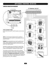
... shipped with optional control devices for mounting, wiring, programming and adjustment. Refer to operate the gate system, must be installed where the user cannot come into contact with the gate while operating the controls where the user has full view of gate operation. See owner's manual for additional information. The following instructions are contrary to the...
... shipped with optional control devices for mounting, wiring, programming and adjustment. Refer to operate the gate system, must be installed where the user cannot come into contact with the gate while operating the controls where the user has full view of gate operation. See owner's manual for additional information. The following instructions are contrary to the...
HS670 GL BOARD Manual
Page 23
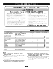
... limit of INJURY or DEATH. 10. can increase the risk of travel, retest the gate operator. 9. Inspection and service should always be performed by a LiftMaster SEMENT AVERTISSEMENT Failure to gate hardware. It is suggested that the incoming voltage to be taken at least 3/4 full ADVERTENCIA... X X Check for leaks X Inspect for tightness Keep at the operator. Using a Digital Voltmeter, verify...
... limit of INJURY or DEATH. 10. can increase the risk of travel, retest the gate operator. 9. Inspection and service should always be performed by a LiftMaster SEMENT AVERTISSEMENT Failure to gate hardware. It is suggested that the incoming voltage to be taken at least 3/4 full ADVERTENCIA... X X Check for leaks X Inspect for tightness Keep at the operator. Using a Digital Voltmeter, verify...

HS670 GL BOARD Manual
Page 26
...master/second communication line. ➤ Review program settings on page 18 and check both the master and second for dual gate operation 3) Master or second unit is not programmed correctly ➤ The power to each unit must be wired incorrectly or malfunctioning. If ... previously in stand-alone mode. ➤ Make sure that the communication wire that the gate will not affect the gate. See important note on operator. GATE EDGE PAUSES GATE WHEN STRUCK DURING OPENING 1) Open obstruction input is programmed incorrectly ➤ The open or interrupt loop LED is not...
...master/second communication line. ➤ Review program settings on page 18 and check both the master and second for dual gate operation 3) Master or second unit is not programmed correctly ➤ The power to each unit must be wired incorrectly or malfunctioning. If ... previously in stand-alone mode. ➤ Make sure that the communication wire that the gate will not affect the gate. See important note on operator. GATE EDGE PAUSES GATE WHEN STRUCK DURING OPENING 1) Open obstruction input is programmed incorrectly ➤ The open or interrupt loop LED is not...


