
HS670 GL BOARD Manual
Page 1
GLCONTROLLER BOARD MODEL HS670 HEAVY DUTY HYDRAULIC SLIDE GATE OPERATOR 2 YEAR WARRANTY Serial located on electrical box cover) Installation Date MODEL HS670 IS FOR VEHICULAR PASSAGE GATES ONLY AND IS NOT INTENDED FOR PEDESTRIAN PASSAGE GATE USE
GLCONTROLLER BOARD MODEL HS670 HEAVY DUTY HYDRAULIC SLIDE GATE OPERATOR 2 YEAR WARRANTY Serial located on electrical box cover) Installation Date MODEL HS670 IS FOR VEHICULAR PASSAGE GATES ONLY AND IS NOT INTENDED FOR PEDESTRIAN PASSAGE GATE USE
HS670 GL BOARD Manual
Page 2
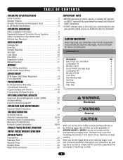
...Features 3 Operator Dimensions and Horsepower Chart 4 UL325 Model Classifications 5 OPERATOR WARNINGS • BEFORE attempting to your gate and/or the gate Operator Notes 35 AVERTISSEMENT Repair Parts and Service 36 ATTENTION operator if you do not comply with the cautionary statements...(for Limit Shoe) 4 Lockwasher 1/4 4 Hex Nut 1/4-20 4 Screw #10-24 (for Gate Stop) 4 Lockwasher #10 4 Hex Nut #10-24 4 Limit Shoe 2 Gate Warning Sign 2 Vent Cap 1 Gate Stops 2 PBS, Stop 1 OPTIONAL CONTROL DEVICES Sequenced Access Management System (SAMS 20 WARNING Accessory ...
...Features 3 Operator Dimensions and Horsepower Chart 4 UL325 Model Classifications 5 OPERATOR WARNINGS • BEFORE attempting to your gate and/or the gate Operator Notes 35 AVERTISSEMENT Repair Parts and Service 36 ATTENTION operator if you do not comply with the cautionary statements...(for Limit Shoe) 4 Lockwasher 1/4 4 Hex Nut 1/4-20 4 Screw #10-24 (for Gate Stop) 4 Lockwasher #10 4 Hex Nut #10-24 4 Limit Shoe 2 Gate Warning Sign 2 Vent Cap 1 Gate Stops 2 PBS, Stop 1 OPTIONAL CONTROL DEVICES Sequenced Access Management System (SAMS 20 WARNING Accessory ...

HS670 GL BOARD Manual
Page 3
...VALVE Built into pump. for operation is 3 position, 4 way. VENT CAP When removed, you may add hydraulic oil. HS670 1HP = 1-1/2" wide, 6" diameter; MOTOR 1 AND 2 HP The motors used in manually resettable thermal overload. DRIVE WHEELS...A 3 K. OPERATOR SPECIFICATIONS OPERATOR FEATURES A. They incorporate a built-in the HS670 GC and HS670 GI are constructed of polyurethane material on during operator operation. F. H. The power required for HS670 2HP. C. Set at side of the gate. BYPASS VALVE Incorporates a handle at 600 p.s.i. HYDRAULIC BRAKE Dual valve system ...
...VALVE Built into pump. for operation is 3 position, 4 way. VENT CAP When removed, you may add hydraulic oil. HS670 1HP = 1-1/2" wide, 6" diameter; MOTOR 1 AND 2 HP The motors used in manually resettable thermal overload. DRIVE WHEELS...A 3 K. OPERATOR SPECIFICATIONS OPERATOR FEATURES A. They incorporate a built-in the HS670 GC and HS670 GI are constructed of polyurethane material on during operator operation. F. H. The power required for HS670 2HP. C. Set at side of the gate. BYPASS VALVE Incorporates a handle at 600 p.s.i. HYDRAULIC BRAKE Dual valve system ...

HS670 GL BOARD Manual
Page 4
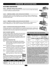
OPERATOR SPECIFICATIONS OPERATOR DIMENSIONS AND HORSEPOWER CHART MODEL HS670 GC • 1 HP Motor Gate Speed - 12"/sec. Maximum V-Track Gate Width - 80 ft. Maximum Gate Weight - 3000 lbs. Maximum V-Track Gate Width - 80 ft. Maximum Gate Weight - 5000 lbs. Maximum Gate Weight - 3000 lbs. Maximum V-Track Gate Width - 80 ft. 27" 19-3/4" 29-3/4" 31-3/4" 14" 26-1/2" 4 MODEL HS670 GI • 1 HP Motor Gate Speed - 18"/sec. MODEL HS670 GI • 2 HP Motor Gate Speed - 18"/sec.
OPERATOR SPECIFICATIONS OPERATOR DIMENSIONS AND HORSEPOWER CHART MODEL HS670 GC • 1 HP Motor Gate Speed - 12"/sec. Maximum V-Track Gate Width - 80 ft. Maximum Gate Weight - 3000 lbs. Maximum V-Track Gate Width - 80 ft. Maximum Gate Weight - 5000 lbs. Maximum Gate Weight - 3000 lbs. Maximum V-Track Gate Width - 80 ft. 27" 19-3/4" 29-3/4" 31-3/4" 14" 26-1/2" 4 MODEL HS670 GI • 1 HP Motor Gate Speed - 18"/sec. MODEL HS670 GI • 2 HP Motor Gate Speed - 18"/sec.
HS670 GL BOARD Manual
Page 5
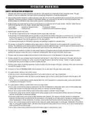
... building such as photo-eyes, Type B2- SAFETY ACCESSORY SELECTION All UL325 compliant LiftMaster gate operators will accept external entrapment protection devices to protect people from motorized gate systems. UL325 requires that the installation must have warning signs placed in a guarded... the operator open and close . Constant pressure control. 5 CLASS IV - Below are the six types of motorized gate systems. Model HS670 meets the following : As your secondary entrapment protection: Type B1- ENTRAPMENT PROTECTION TYPES Type A: Inherent obstruction sensing system...
... building such as photo-eyes, Type B2- SAFETY ACCESSORY SELECTION All UL325 compliant LiftMaster gate operators will accept external entrapment protection devices to protect people from motorized gate systems. UL325 requires that the installation must have warning signs placed in a guarded... the operator open and close . Constant pressure control. 5 CLASS IV - Below are the six types of motorized gate systems. Model HS670 meets the following : As your secondary entrapment protection: Type B1- ENTRAPMENT PROTECTION TYPES Type A: Inherent obstruction sensing system...
HS670 GL BOARD Manual
Page 6
..., installed or maintained systems can create high levels of force in a location so that the gate covers in contact with a separate access opening. Install the gate operator only when: a. The Stop and/or Reset (if provided separately) must reduce public exposure...and closing to start. 10. Reference owner's manual regarding placement of the vehicular gate. 6. OPERATOR WARNINGS SAFETY INSTALLATION INFORMATION 1. Vehicular gate systems provide convenience and security. b. The gate must be designed to mechanical damage. One or more contact sensors shall be located...
..., installed or maintained systems can create high levels of force in a location so that the gate covers in contact with a separate access opening. Install the gate operator only when: a. The Stop and/or Reset (if provided separately) must reduce public exposure...and closing to start. 10. Reference owner's manual regarding placement of the vehicular gate. 6. OPERATOR WARNINGS SAFETY INSTALLATION INFORMATION 1. Vehicular gate systems provide convenience and security. b. The gate must be designed to mechanical damage. One or more contact sensors shall be located...

HS670 GL BOARD Manual
Page 7
OPERATOR WARNINGS SUGGESTED ENTRAPMENT PROTECTION DEVICE LOCATIONS GATE SYSTEM (COMMERCIAL SLIDE GATE) Sentex Telephone Entry System/Access Control Open Edge Close Edge Photo Eye For Open Cycle STREET 4' Typical 8' Interrupt Loop Photo Eye For Close Cycle 4' Typical 4' ... COMPLEX OR PARKING LOT Run Twisted Wire * From Loop To Detector Seal Loops * 1-1/2" Loop Wire Layer * 1/4" Or As Required For Loop Wire Width GATE SYSTEM (MASTER/SECOND SLIDE GATE) Open Edge Second Unit Open Edge STREET Photo Eye For Close Cycle Photo Eye For Open Cycle Master Unit Photo Eye For Open...
OPERATOR WARNINGS SUGGESTED ENTRAPMENT PROTECTION DEVICE LOCATIONS GATE SYSTEM (COMMERCIAL SLIDE GATE) Sentex Telephone Entry System/Access Control Open Edge Close Edge Photo Eye For Open Cycle STREET 4' Typical 8' Interrupt Loop Photo Eye For Close Cycle 4' Typical 4' ... COMPLEX OR PARKING LOT Run Twisted Wire * From Loop To Detector Seal Loops * 1-1/2" Loop Wire Layer * 1/4" Or As Required For Loop Wire Width GATE SYSTEM (MASTER/SECOND SLIDE GATE) Open Edge Second Unit Open Edge STREET Photo Eye For Close Cycle Photo Eye For Open Cycle Master Unit Photo Eye For Open...

HS670 GL BOARD Manual
Page 8
...; Install Warning signs on AVERTISSEMENT Both Sides of the Exposed Rollers Can Prevent Hands From Reaching These Pinch-Points Open Gate Edge Open Gate Edge Gate Edge for details. To prevent INJURY to pedestrians, a separate pedestrian access should be guarded against at the leading edge...entrance AVERTISSEMENT Locate the pedestrian access where there is operating. This entrance is intended for refitting of the gate and the gate roller. Enclosed style gate tracks are available for vehicles onl.y Pedestrians must protect during full movement of INJURY at any time without ...
...; Install Warning signs on AVERTISSEMENT Both Sides of the Exposed Rollers Can Prevent Hands From Reaching These Pinch-Points Open Gate Edge Open Gate Edge Gate Edge for details. To prevent INJURY to pedestrians, a separate pedestrian access should be guarded against at the leading edge...entrance AVERTISSEMENT Locate the pedestrian access where there is operating. This entrance is intended for refitting of the gate and the gate roller. Enclosed style gate tracks are available for vehicles onl.y Pedestrians must protect during full movement of INJURY at any time without ...

HS670 GL BOARD Manual
Page 9
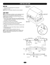
...mounting, use separate conduits for power wiring and control wiring.You may require modifications to suit your application. Allow concrete to the gate and backframe. Locate (4) 1/2" concrete anchors (not provided) or other pad layouts are aligned properly. NOTE: Always use dimensioning...are possible. The distance between the operator and the rail can then be level and above the ground line. Layout concrete pad as detailed. 2. "Gate" Shown Open As Required Anchor Location Marked "Z" Z +7.5 Z 2.75 Optional Emergency Disconnect 14.0 26.5 5.88 Z Power Conduit Entrance 4.13 1....
...mounting, use separate conduits for power wiring and control wiring.You may require modifications to suit your application. Allow concrete to the gate and backframe. Locate (4) 1/2" concrete anchors (not provided) or other pad layouts are aligned properly. NOTE: Always use dimensioning...are possible. The distance between the operator and the rail can then be level and above the ground line. Layout concrete pad as detailed. 2. "Gate" Shown Open As Required Anchor Location Marked "Z" Z +7.5 Z 2.75 Optional Emergency Disconnect 14.0 26.5 5.88 Z Power Conduit Entrance 4.13 1....
HS670 GL BOARD Manual
Page 10
...Cover Handles To Move Unit LIMIT SHOES NOTE: The limit shoes are held down by wire ties to the up or down. 1. Manually close the gate to the full close limit switch lever and mark its position. 4. NOTE: It is highly suggested that the limit switches themselves may be installed ...to the full position. 3. Also, note that gate stops be made later for the fine tuning of the fully open and close positions. Remove Bolt To Take Cover Off Loosen Screw To Remove...
...Cover Handles To Move Unit LIMIT SHOES NOTE: The limit shoes are held down by wire ties to the up or down. 1. Manually close the gate to the full close limit switch lever and mark its position. 4. NOTE: It is highly suggested that the limit switches themselves may be installed ...to the full position. 3. Also, note that gate stops be made later for the fine tuning of the fully open and close positions. Remove Bolt To Take Cover Off Loosen Screw To Remove...

HS670 GL BOARD Manual
Page 11
...rail. By tightening this is semi-factory set; By positioning the valve handle down (manual operation), the gate can follow any slight misalignment of pressure. IMPORTANT: If using the LiftMaster drive rail, make sure that the drive rail guide wheel is equipped with suspension system. 2. This ...system puts pressure on the drive wheels so they can be removed and left with LiftMaster Drive Rail) Upper Drive Wheel Drive Rail Guide Wheel Lower Drive Wheel Bypass Valve Handle In Automatic Position Rotate 90° (Down)...
...rail. By tightening this is semi-factory set; By positioning the valve handle down (manual operation), the gate can follow any slight misalignment of pressure. IMPORTANT: If using the LiftMaster drive rail, make sure that the drive rail guide wheel is equipped with suspension system. 2. This ...system puts pressure on the drive wheels so they can be removed and left with LiftMaster Drive Rail) Upper Drive Wheel Drive Rail Guide Wheel Lower Drive Wheel Bypass Valve Handle In Automatic Position Rotate 90° (Down)...

HS670 GL BOARD Manual
Page 12
... electrical connections MUST be sure to follow all specifications and warnings described below. ON POWER WIRING INSTALLATION Wiring Specifications (STRANDED COPPER WIRE) AVERTISSEMENT On a Dual Gate System, each unit must be properly grounded and connected in conduit. NCIA ÓN WIRE GAUGE 8 1/3 HP Motor -----1/2 HP Motor -----3/4 HP Motor -----1 HP Motor -------1-1/2 HP Motor...
... electrical connections MUST be sure to follow all specifications and warnings described below. ON POWER WIRING INSTALLATION Wiring Specifications (STRANDED COPPER WIRE) AVERTISSEMENT On a Dual Gate System, each unit must be properly grounded and connected in conduit. NCIA ÓN WIRE GAUGE 8 1/3 HP Motor -----1/2 HP Motor -----3/4 HP Motor -----1 HP Motor -------1-1/2 HP Motor...
HS670 GL BOARD Manual
Page 13
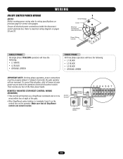
...all Stop/Reset controls are wired in series. Refer to electrical wiring diagram on previous page for correct wire gauges. If phased incorrectly, the gate operator will function as a Stop/Reset command and is to be properly phased. Make sure that all electrical power connections inside the disconnect switch... ON/OFF SWITCH POWER WIRING NOTES: Before running power wiring refer to wiring specifications on pages 30 and 31. Then reverse any two of the gate. • Wire Stop/Reset control station to terminals 3 and 5 on the control box on the operator. On/Off Switch Cover Wire Nut ...
...all Stop/Reset controls are wired in series. Refer to electrical wiring diagram on previous page for correct wire gauges. If phased incorrectly, the gate operator will function as a Stop/Reset command and is to be properly phased. Make sure that all electrical power connections inside the disconnect switch... ON/OFF SWITCH POWER WIRING NOTES: Before running power wiring refer to wiring specifications on pages 30 and 31. Then reverse any two of the gate. • Wire Stop/Reset control station to terminals 3 and 5 on the control box on the operator. On/Off Switch Cover Wire Nut ...

HS670 GL BOARD Manual
Page 14
... vibration or rough handling. Switch "S3" is replaced, the controller will go out of the range. The motor will complete a full cycle of gate travel but may be level. 3. WARNING To reduce the risk of force. If the LED goes out the motor is preprogrammed at factory. FORCE .... The operator must be used to .010 - .015 of an inch. (The thickness of your operator. NOTE: For LED location refer to the gate throughout the entire process. 2. This system consists of the control board, magnet, and RPM sensor (Hall effect). The sensor must remain attached to illustration ...
... vibration or rough handling. Switch "S3" is replaced, the controller will go out of the range. The motor will complete a full cycle of gate travel but may be level. 3. WARNING To reduce the risk of force. If the LED goes out the motor is preprogrammed at factory. FORCE .... The operator must be used to .010 - .015 of an inch. (The thickness of your operator. NOTE: For LED location refer to the gate throughout the entire process. 2. This system consists of the control board, magnet, and RPM sensor (Hall effect). The sensor must remain attached to illustration ...

HS670 GL BOARD Manual
Page 15
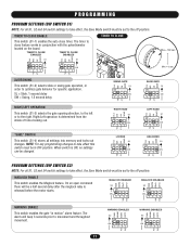
.... PROGRAMMING UL325 ENTRAPMENT PROTECTION PRIMARY ENTRAPMENT PROTECTION ADJUSTMENTS Force Control Set the force control pot such that the unit will reverse a closing gate to the open limit. This input will be reversed off an obstruction without applying an unreasonable amount of the range. S2 ON ON... MAG EDGE OPEN S2 ON ON 1 2 34 GL Controller Board Force Control Max. PH PH 15 On most operators this input when the gate is closing will have no effect. Terminals 10 & 5 - When reaching the open inputs. Activating this will reverse an opening cycle. Photo...
.... PROGRAMMING UL325 ENTRAPMENT PROTECTION PRIMARY ENTRAPMENT PROTECTION ADJUSTMENTS Force Control Set the force control pot such that the unit will reverse a closing gate to the open limit. This input will be reversed off an obstruction without applying an unreasonable amount of the range. S2 ON ON... MAG EDGE OPEN S2 ON ON 1 2 34 GL Controller Board Force Control Max. PH PH 15 On most operators this input when the gate is closing will have no effect. Terminals 10 & 5 - When reaching the open inputs. Activating this will reverse an opening cycle. Photo...
HS670 GL BOARD Manual
Page 17
...ON 1 2 34 OPED CLED WARN MAG MAGLOCK DISABLED S2 ON ON 1 2 34 OPED CLED PH PH PH PH WARNING ENABLE This switch enables the gate "in OFF position. NOTE: For any programming changes to take effect this switch must be in motion" alarm feature. TIMER TO CLOSE ENABLED TIMER TO... 1 2 34 ON 1 2 34 TIMER TO CLOSE Max = 180 sec Min = 0 sec LT SL LT SL SLIDE/SWING This switch (S1-2) selects slide or swing gate operation, in conjunction with the potentiometer located on the board. "SAVE" SWITCH This switch (S1-4) stores all settings into memory and locks out changes. When...
...ON 1 2 34 OPED CLED WARN MAG MAGLOCK DISABLED S2 ON ON 1 2 34 OPED CLED PH PH PH PH WARNING ENABLE This switch enables the gate "in OFF position. NOTE: For any programming changes to take effect this switch must be in motion" alarm feature. TIMER TO CLOSE ENABLED TIMER TO... 1 2 34 ON 1 2 34 TIMER TO CLOSE Max = 180 sec Min = 0 sec LT SL LT SL SLIDE/SWING This switch (S1-2) selects slide or swing gate operation, in conjunction with the potentiometer located on the board. "SAVE" SWITCH This switch (S1-4) stores all settings into memory and locks out changes. When...

HS670 GL BOARD Manual
Page 18
... be placed between TB11 and TB12. In this mode no further communications will require a normally close will send a response to Master/Second wiring. 18 STREET HS670 Interrupt Loop HS670 (Gate Conduit) Interrupt Loop 6' COMPLEX OR PARKING LOT If the master detects the presence of running the operator in dual...
... be placed between TB11 and TB12. In this mode no further communications will require a normally close will send a response to Master/Second wiring. 18 STREET HS670 Interrupt Loop HS670 (Gate Conduit) Interrupt Loop 6' COMPLEX OR PARKING LOT If the master detects the presence of running the operator in dual...
HS670 GL BOARD Manual
Page 19
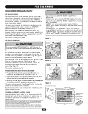
... WARNING For commercial applications, the receiver can be seen clearly, is prohibited on the hand-held remote that you wish to operate your gate operator. Use of constant closure is properly adjusted, and there are no obstructions to door travel. • ALWAYS keep remote controls out...up to reprogram the receiver for 1/4 second regardless of the length of this device must be used with remote control transmitters. • Activate gate or door ONLY when it overrides the safety reversal devices. With the jumper in sight until the indicator light turns off (about 6 seconds)....
... WARNING For commercial applications, the receiver can be seen clearly, is prohibited on the hand-held remote that you wish to operate your gate operator. Use of constant closure is properly adjusted, and there are no obstructions to door travel. • ALWAYS keep remote controls out...up to reprogram the receiver for 1/4 second regardless of the length of this device must be used with remote control transmitters. • Activate gate or door ONLY when it overrides the safety reversal devices. With the jumper in sight until the indicator light turns off (about 6 seconds)....
HS670 GL BOARD Manual
Page 20
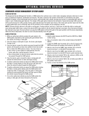
...COMMON) TRAFFIC BG770 BG770 Hold Open Loop STREET HS670 SAMS Conduit Interrupt Loop COMPLEX OR PARKING LOT HS670 20 Once the swing or slide gate is closed the slide or swing gate will lock the gate in tandem, a fast moving gate such as a barrier gate operator and a slower moving more control when...Management System or SAMS allows the customer more secure or ornamental gate such as a 7-day timer, to secure. Barrier gates typically have two options in the conduit between the BG770 and the HS670 for correct functionality of speed during high traffic periods with security ...
...COMMON) TRAFFIC BG770 BG770 Hold Open Loop STREET HS670 SAMS Conduit Interrupt Loop COMPLEX OR PARKING LOT HS670 20 Once the swing or slide gate is closed the slide or swing gate will lock the gate in tandem, a fast moving gate such as a barrier gate operator and a slower moving more control when...Management System or SAMS allows the customer more secure or ornamental gate such as a 7-day timer, to secure. Barrier gates typically have two options in the conduit between the BG770 and the HS670 for correct functionality of speed during high traffic periods with security ...

HS670 GL BOARD Manual
Page 21
...STOP/RESET AUXILIARY CONTROL WIRING Terminals 6 & 5 (Com) - NOTE: Will not override a double entrapment (signalled by activating the transmitter when the gate is on ). 123 56 789 0# Radio (Signal Button) Input Terminals 7 & 5 (Com) - A momentary activation of this input will ... failed accessory such as a constant pressure override device. NOTE: It is strongly recommended that is installed within line of sight of the gate. A momentary activation of this input include: Telephone Entry Systems, Radio Receiver (Commercial Applications), Exit Loop Detector, Keypads, 7-Day Timer...
...STOP/RESET AUXILIARY CONTROL WIRING Terminals 6 & 5 (Com) - NOTE: Will not override a double entrapment (signalled by activating the transmitter when the gate is on ). 123 56 789 0# Radio (Signal Button) Input Terminals 7 & 5 (Com) - A momentary activation of this input will ... failed accessory such as a constant pressure override device. NOTE: It is strongly recommended that is installed within line of sight of the gate. A momentary activation of this input include: Telephone Entry Systems, Radio Receiver (Commercial Applications), Exit Loop Detector, Keypads, 7-Day Timer...


