Owners Manual
Page 2
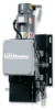
... A REVERSING EDGE IS STRONGLY RECOMMENDED FOR ALL COMMERCIAL OPERATOR INSTALLATIONS. with open , constant pressure to close and stop on left or right side. See schematic diagram on page 12 for instructions on door OUTPUT SHAFT 1.5" Dia. ELECTRICAL TRANSFORMER 3PH: 208/230/480 VAC 24VAC ...Sec GEAR BOX Worm gear LUBRICATION Oil Bath RATIO 45:1 OUTPUT SPEED 38 rpm DOOR SPEED 5" per hour DELAY ON REVERSE:.......Standard SAFETY REVERSING EDGE:.......(Optional) Electric or pneumatic sensing device attached to open and close with 3/8" Keyway. 26.38" 2 7.87" 11.61" ...
... A REVERSING EDGE IS STRONGLY RECOMMENDED FOR ALL COMMERCIAL OPERATOR INSTALLATIONS. with open , constant pressure to close and stop on left or right side. See schematic diagram on page 12 for instructions on door OUTPUT SHAFT 1.5" Dia. ELECTRICAL TRANSFORMER 3PH: 208/230/480 VAC 24VAC ...Sec GEAR BOX Worm gear LUBRICATION Oil Bath RATIO 45:1 OUTPUT SPEED 38 rpm DOOR SPEED 5" per hour DELAY ON REVERSE:.......Standard SAFETY REVERSING EDGE:.......(Optional) Electric or pneumatic sensing device attached to open and close with 3/8" Keyway. 26.38" 2 7.87" 11.61" ...

Owners Manual
Page 3
... below if you require the hand chain and/or disconnect chain to the door shaft. SECURE LOCK(S) IN "OPEN" POSITION. MIN. In reverse of disassembly, install the chain wheel assembly on the opposite side of door, and in a horizontal position. DOORS, DOOR SPRINGS, CABLES, PULLEYS, BRACKETS AND THEIR HARDWARE MAY BE UNDER EXTREME TENSION AND...
... below if you require the hand chain and/or disconnect chain to the door shaft. SECURE LOCK(S) IN "OPEN" POSITION. MIN. In reverse of disassembly, install the chain wheel assembly on the opposite side of door, and in a horizontal position. DOORS, DOOR SPRINGS, CABLES, PULLEYS, BRACKETS AND THEIR HARDWARE MAY BE UNDER EXTREME TENSION AND...

Owners Manual
Page 5
... on one side or the other of emergency or power failure. The disconnect chain may be released from the chain keeper before the door will disable the electrical controls when the hoist is equipped with pad locking provisions) Manual Hoist 5 Mount Chain Keeper / Keyhole Bracket...to assure full engagment. Install Hand Chain Place hand chain around hand chain wheel. To operate the hoist: 1. 7. Place end through both openings in the chain guide. An electrical interlock will operate again electrically. Remove enough links so chain hangs approximately two feet above the floor, ...
... on one side or the other of emergency or power failure. The disconnect chain may be released from the chain keeper before the door will disable the electrical controls when the hoist is equipped with pad locking provisions) Manual Hoist 5 Mount Chain Keeper / Keyhole Bracket...to assure full engagment. Install Hand Chain Place hand chain around hand chain wheel. To operate the hoist: 1. 7. Place end through both openings in the chain guide. An electrical interlock will operate again electrically. Remove enough links so chain hangs approximately two feet above the floor, ...
Owners Manual
Page 6
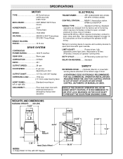
... stop in accordance with local codes. The sensing edge may be installed 12" above the top of the door. TAKE-UP REEL: Take-up the door opening . 4. WARNING W 2. See field connection terminals identified as described below . To adjust limit nuts depress retaining plate to allow nut to... CONJUNCTION WITH THIS OPERATOR. ENTRAPMENT PROTECTION ACCESSORIES (OPTIONAL) SENSING EDGES All types of sensing edges with an isolated normally open position with the bottom of the door even with top of door opening . Repeat Steps 1 and 2 for CAUTION assistance - 1-800-528-2806.
... stop in accordance with local codes. The sensing edge may be installed 12" above the top of the door. TAKE-UP REEL: Take-up the door opening . 4. WARNING W 2. See field connection terminals identified as described below . To adjust limit nuts depress retaining plate to allow nut to... CONJUNCTION WITH THIS OPERATOR. ENTRAPMENT PROTECTION ACCESSORIES (OPTIONAL) SENSING EDGES All types of sensing edges with an isolated normally open position with the bottom of the door even with top of door opening . Repeat Steps 1 and 2 for CAUTION assistance - 1-800-528-2806.
Owners Manual
Page 7
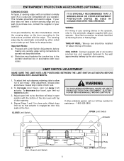
... UTION DISCONNECT POWER AT THE FUSE BOX BEFORE PROCEEDING. WARNING ALL ELECTRICAL CONNECTIONS MUST BE MADE BY A QUALIFIED INDIVIDUAL. SECURE LOCK(S) IN "OPEN" POSITION. A GROUND SCREW IS SUPPLIED IN THE ELECTRICAL BOX FOR CONNECTION OF THE POWER SUPPLY GROUND WIRE. FAILURE TO PROPERLY GROUND THIS UNIT... DO NOT INSTALL ANY WIRING OR ATTEMPT TO RUN THIS OPERATOR WITHOUT CONSULTING THE WIRING DIAGRAM. WARNING TO AVOID DAMAGE TO DOOR AND OPERATOR, MAKE ALL DOOR LOCKS INOPERATIVE. IMPORTANT: THIS UNIT MUST BE PROPERLY GROUNDED. WARNING Do Not Run Power & Control Wiring in the Same Conduit...
... UTION DISCONNECT POWER AT THE FUSE BOX BEFORE PROCEEDING. WARNING ALL ELECTRICAL CONNECTIONS MUST BE MADE BY A QUALIFIED INDIVIDUAL. SECURE LOCK(S) IN "OPEN" POSITION. A GROUND SCREW IS SUPPLIED IN THE ELECTRICAL BOX FOR CONNECTION OF THE POWER SUPPLY GROUND WIRE. FAILURE TO PROPERLY GROUND THIS UNIT... DO NOT INSTALL ANY WIRING OR ATTEMPT TO RUN THIS OPERATOR WITHOUT CONSULTING THE WIRING DIAGRAM. WARNING TO AVOID DAMAGE TO DOOR AND OPERATOR, MAKE ALL DOOR LOCKS INOPERATIVE. IMPORTANT: THIS UNIT MUST BE PROPERLY GROUNDED. WARNING Do Not Run Power & Control Wiring in the Same Conduit...
Owners Manual
Page 8
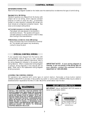
... supplied with jumper set for all connections. Generally a three button station (OPEN/CLOSE/STOP) is missing, or you must include an entrapment protection device. IF CONTROL STATION CANNOT BE INSTALLED WHERE DOOR IS VISIBLE, OR IF ANY DEVICE OTHER THAN THE CONTROL STATION IS USED...close direction. MOUNT WARNING NOTICE WARNING IMPORTANT: Mount WARNING NOTICE beside or below . Control Station Push Buttons OPEN WARNING CLOSE TO PREVENT ENTRAPMENT WARNING DO NOT START DOOR DOWNWARD UNLESS DOORWAY IS CLEAR STOP WARNING Notice 8 CONTROL WIRING DETERMINE WIRING TYPE Refer to the wiring ...
... supplied with jumper set for all connections. Generally a three button station (OPEN/CLOSE/STOP) is missing, or you must include an entrapment protection device. IF CONTROL STATION CANNOT BE INSTALLED WHERE DOOR IS VISIBLE, OR IF ANY DEVICE OTHER THAN THE CONTROL STATION IS USED...close direction. MOUNT WARNING NOTICE WARNING IMPORTANT: Mount WARNING NOTICE beside or below . Control Station Push Buttons OPEN WARNING CLOSE TO PREVENT ENTRAPMENT WARNING DO NOT START DOOR DOWNWARD UNLESS DOORWAY IS CLEAR STOP WARNING Notice 8 CONTROL WIRING DETERMINE WIRING TYPE Refer to the wiring ...
Owners Manual
Page 9
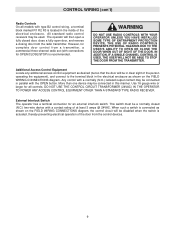
... CONTROLS WITH YOUR OPERATOR UNLESS YOU HAVE INSTALLED fully closed (N.C.) two-wire device with connections for OPEN/CLOSE/STOP) is actuated, thereby preventing electrical operation of the door from the control devices. 9 Use 16 gauge wire or larger for an external interlock switch. ... WARNING W block marked R1 R2 R3 is connected as shown on the FIELD WIRING CONNECTIONS diagram, the control circuit will then open door, and reverse a closing door from a transmitter, a commercial three-channel radio set (with a contact rating of the electrical enclosure. More than one device may...
... CONTROLS WITH YOUR OPERATOR UNLESS YOU HAVE INSTALLED fully closed (N.C.) two-wire device with connections for OPEN/CLOSE/STOP) is actuated, thereby preventing electrical operation of the door from the control devices. 9 Use 16 gauge wire or larger for an external interlock switch. ... WARNING W block marked R1 R2 R3 is connected as shown on the FIELD WIRING CONNECTIONS diagram, the control circuit will then open door, and reverse a closing door from a transmitter, a commercial three-channel radio set (with a contact rating of the electrical enclosure. More than one device may...
Owners Manual
Page 10
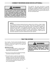
... equipment in a residential area is operated in accordance with the limits for a Class A digital device, pursuant to electrically operate the door in which case the user will deactivate the safety device during the last few inches of a reversing edge device. This equipment generates,...DEVICES. CAUTION Be sure the owner or person(s) responsible for fine adjustment WARNING W of the FCC Rules. Connect the normally open contacts to make sure they are working properly. ALWAYS DISCONNECT POWER and entrapment protection devices have read and understand the Safety Instructions,...
... equipment in a residential area is operated in accordance with the limits for a Class A digital device, pursuant to electrically operate the door in which case the user will deactivate the safety device during the last few inches of a reversing edge device. This equipment generates,...DEVICES. CAUTION Be sure the owner or person(s) responsible for fine adjustment WARNING W of the FCC Rules. Connect the normally open contacts to make sure they are working properly. ALWAYS DISCONNECT POWER and entrapment protection devices have read and understand the Safety Instructions,...


