8355 Manual
Page 1
... Garage Door Opener Model 8355 - 1/2 hp FOR RESIDENTIAL USE ONLY ■ Please read this manual and the enclosed safety materials carefully! ■ Fasten the manual near the garage door after installation. ■ The door WILL NOT CLOSE unless the Protector System® is located on a one-piece door, visit www.liftmaster.com for future reference...
... Garage Door Opener Model 8355 - 1/2 hp FOR RESIDENTIAL USE ONLY ■ Please read this manual and the enclosed safety materials carefully! ■ Fasten the manual near the garage door after installation. ■ The door WILL NOT CLOSE unless the Protector System® is located on a one-piece door, visit www.liftmaster.com for future reference...
8355 Manual
Page 2
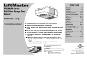
...springs. 3. Preparation Safety Symbol and Signal Word Review This garage door opener has been designed and tested to offer safe service provided it is installed, operated, maintained and tested in strict accordance with the warnings that accompany it. If balanced, it may not work properly. 5. If there...check for binding or sticking. Otherwise, the safety reversal system may be installed above the center of the door center. If your garage door and/or the garage door opener if you see this manual. Read the warnings carefully. Lift the door halfway up. Torsion Spring OR...
...springs. 3. Preparation Safety Symbol and Signal Word Review This garage door opener has been designed and tested to offer safe service provided it is installed, operated, maintained and tested in strict accordance with the warnings that accompany it. If balanced, it may not work properly. 5. If there...check for binding or sticking. Otherwise, the safety reversal system may be installed above the center of the door center. If your garage door and/or the garage door opener if you see this manual. Read the warnings carefully. Lift the door halfway up. Torsion Spring OR...
8355 Manual
Page 3
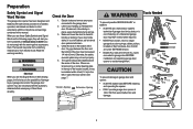
... hex screws K. Trolley G. Safety labels and literature P. A. Pulley and bracket C. Rail I SECURITY✚ 2.0TM ACCESSORIES 882LM Multi-Function Door Control 893LM Remote Control Hardware Installation Hex Bolt 5/16"-18 x 7/8" (4) Lag Screw 5/16"-9 x 1-5/8" (2) Clevis Pin 5/16" x 2-3/4" (1) Clevis Pin 5/16" x 1-1/4" (1) Clevis Pin ...may be attached to the accessory and are not included in this manual are for reference and your garage door opener. The images throughout this manual. Rail grease H L M Not Provided J Not Provided N O P I . Emergency release rope and ...
... hex screws K. Trolley G. Safety labels and literature P. A. Pulley and bracket C. Rail I SECURITY✚ 2.0TM ACCESSORIES 882LM Multi-Function Door Control 893LM Remote Control Hardware Installation Hex Bolt 5/16"-18 x 7/8" (4) Lag Screw 5/16"-9 x 1-5/8" (2) Clevis Pin 5/16" x 2-3/4" (1) Clevis Pin 5/16" x 1-1/4" (1) Clevis Pin ...may be attached to the accessory and are not included in this manual are for reference and your garage door opener. The images throughout this manual. Rail grease H L M Not Provided J Not Provided N O P I . Emergency release rope and ...
8355 Manual
Page 6
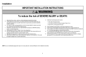
...manual release/safety reverse test label in SEVERE INJURY or DEATH. 3. Installation IMPORTANT INSTALLATION INSTRUCTIONS WARNING To reduce the risk of installation, test safety reversal system. Disable ALL locks and remove ALL ropes connected to garage door BEFORE installing opener to -Close functionality if operating either one -piece door, visit www.liftmaster.com for installation... instructions. 6 NOTE: If you are installing the garage door opener ...
...manual release/safety reverse test label in SEVERE INJURY or DEATH. 3. Installation IMPORTANT INSTALLATION INSTRUCTIONS WARNING To reduce the risk of installation, test safety reversal system. Disable ALL locks and remove ALL ropes connected to garage door BEFORE installing opener to -Close functionality if operating either one -piece door, visit www.liftmaster.com for installation... instructions. 6 NOTE: If you are installing the garage door opener ...
8355 Manual
Page 10
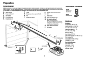
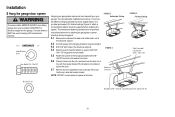
Concrete anchors MUST be different. Yours may be used if installing ANY brackets into masonry. Operate the door manually. Installation 5 Hang the garage door opener To avoid possible SERIOUS INJURY from each bracket to a support with 5/16"- 18x1-7/8" lag ...motor unit to the structural support. 5.2 Cut both pieces of the hanging bracket to structural supports before installing the opener. NOTE: DO NOT connect power to provide rigid support. Two representative installations are not provided. On finished ceilings (Figure 2), attach a sturdy metal bracket to required lengths. ...
Concrete anchors MUST be different. Yours may be used if installing ANY brackets into masonry. Operate the door manually. Installation 5 Hang the garage door opener To avoid possible SERIOUS INJURY from each bracket to a support with 5/16"- 18x1-7/8" lag ...motor unit to the structural support. 5.2 Cut both pieces of the hanging bracket to structural supports before installing the opener. NOTE: DO NOT connect power to provide rigid support. Two representative installations are not provided. On finished ceilings (Figure 2), attach a sturdy metal bracket to required lengths. ...
8355 Manual
Page 16
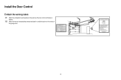
Install the Door Control 3 Attach the warning labels 3.1 Attach the entrapment warning label on the wall near the door control with tacks or staples. 3.2 Attach the manual release/safety reverse test label in a visible location on the inside of the garage door. 16
Install the Door Control 3 Attach the warning labels 3.1 Attach the entrapment warning label on the wall near the door control with tacks or staples. 3.2 Attach the manual release/safety reverse test label in a visible location on the inside of the garage door. 16
8355 Manual
Page 33
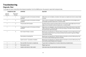
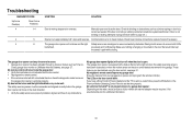
... The garage door opener will not close and the light bulbs flash. The door control will not close the door. Safety sensors are not installed, connected or wires may be cut wire. Make sure nothing is a short or reversed wire for binding or obstructions, such as a broken...or correct as needed . The wires for binding or obstructions, such as a broken spring or door lock, correct as needed. Replace logic board. Manually open and close and the light bulbs flash. Check for 1-2 seconds no movement. Door moves 6-8" stops or reverses. Opener hums for binding or ...
... The garage door opener will not close and the light bulbs flash. The door control will not close the door. Safety sensors are not installed, connected or wires may be cut wire. Make sure nothing is a short or reversed wire for binding or obstructions, such as a broken...or correct as needed . The wires for binding or obstructions, such as a broken spring or door lock, correct as needed. Replace logic board. Manually open and close and the light bulbs flash. Check for 1-2 seconds no movement. Door moves 6-8" stops or reverses. Opener hums for binding or ...
8355 Manual
Page 34
Manually open : The garage door opener is equipped with a feature that turns the light on when the safety reversing sensors have a Smart Control Panel installed and the TTC is not activated on the door that would interrupt the sensor's path while closing. My remote ...to page 24 ). Safety sensors are steady and not flickering. These features can beep for additional information. 34 Close, garage door monitor or LiftMaster Internet Gateway, see page 31 . The garage door opener will move in the garage. The garage door opener can be required. Opener runs...
Manually open : The garage door opener is equipped with a feature that turns the light on when the safety reversing sensors have a Smart Control Panel installed and the TTC is not activated on the door that would interrupt the sensor's path while closing. My remote ...to page 24 ). Safety sensors are steady and not flickering. These features can beep for additional information. 34 Close, garage door monitor or LiftMaster Internet Gateway, see page 31 . The garage door opener will move in the garage. The garage door opener can be required. Opener runs...
8355 Manual
Page 37
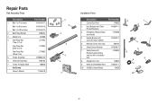
... 8 feet (2.4 m) One-Piece Rail 10 feet (3 m) 5 Trolley Assembly 6 Tensioner Assembly 7 Trolley Threaded Shaft Not Shown Owner's Manual Part Number 41A5434-11 41A5434-13 41A5434-14 41B5424 4A1008 2777BD 2778BD 2770BD 41B3869-3A 41B4103 109B48 114A4419 3 6 2 4 7 5 1 Installation Parts Description Part Number 1 Curved Door Arm 178B35 2 Door Bracket with Clevis Pin and Fastener 41A5047...
... 8 feet (2.4 m) One-Piece Rail 10 feet (3 m) 5 Trolley Assembly 6 Tensioner Assembly 7 Trolley Threaded Shaft Not Shown Owner's Manual Part Number 41A5434-11 41A5434-13 41A5434-14 41B5424 4A1008 2777BD 2778BD 2770BD 41B3869-3A 41B4103 109B48 114A4419 3 6 2 4 7 5 1 Installation Parts Description Part Number 1 Curved Door Arm 178B35 2 Door Bracket with Clevis Pin and Fastener 41A5047...


