
3585 Elite Series Manual
Page 1
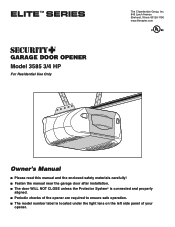
® GARAGE DOOR OPENER Model 3585 3/4 HP For Residential Use Only The Chamberlain Group, Inc. 845 Larch Avenue Elmhurst, Illinois 60126-1196 www.liftmaster.com Owner's Manual ■ Please read this manual and the enclosed safety materials carefully! ■ Fasten the manual near the garage door after installation. ■ The door WILL NOT CLOSE unless the Protector System...
® GARAGE DOOR OPENER Model 3585 3/4 HP For Residential Use Only The Chamberlain Group, Inc. 845 Larch Avenue Elmhurst, Illinois 60126-1196 www.liftmaster.com Owner's Manual ■ Please read this manual and the enclosed safety materials carefully! ■ Fasten the manual near the garage door after installation. ■ The door WILL NOT CLOSE unless the Protector System...
3585 Elite Series Manual
Page 2
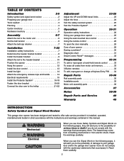
...36 Accessories 37 Notes 38-39 Repair Parts and Service 40 Warranty 40 INTRODUCTION Safety Symbol and Signal Word Review This garage door opener has been designed and tested to offer safe service provided it . Read the warnings carefully. Read them . ...TABLE OF CONTENTS Introduction 2-5 Safety symbol and signal word review 2 Preparing your garage door 3 Tools needed 3 Planning 4 Carton inventory 5 Hardware inventory 5 Assembly 6-7 Attach the rail to the motor unit 6 Set the belt tension...
...36 Accessories 37 Notes 38-39 Repair Parts and Service 40 Warranty 40 INTRODUCTION Safety Symbol and Signal Word Review This garage door opener has been designed and tested to offer safe service provided it . Read the warnings carefully. Read them . ...TABLE OF CONTENTS Introduction 2-5 Safety symbol and signal word review 2 Preparing your garage door 3 Tools needed 3 Planning 4 Carton inventory 5 Hardware inventory 5 Assembly 6-7 Attach the rail to the motor unit 6 Set the belt tension...

3585 Elite Series Manual
Page 3
.... • Disable ALL locks and remove ALL ropes connected to garage door BEFORE installing and operating garage door opener to avoid entanglement. Preparing your garage door Before you begin: • Disable locks. • Remove any ropes connected to garage door. • Complete the following test to make sure your door binds, sticks, or is any binding or sticking. Release...
.... • Disable ALL locks and remove ALL ropes connected to garage door BEFORE installing and operating garage door opener to avoid entanglement. Preparing your garage door Before you begin: • Disable locks. • Remove any ropes connected to garage door. • Complete the following test to make sure your door binds, sticks, or is any binding or sticking. Release...
3585 Elite Series Manual
Page 4
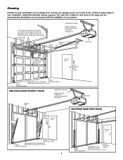
... refer back to this page and the accompanying illustrations as you proceed with glass panels, etc.). See page 19 for lightweight garage doors (fiberglass, steel, aluminum, door with the installation of your garage door. You may be required. Torsion Spring Extension Spring OR Motor Unit --- --- -- See page 12. See page 12. Planning Identify the type...
... refer back to this page and the accompanying illustrations as you proceed with glass panels, etc.). See page 19 for lightweight garage doors (fiberglass, steel, aluminum, door with the installation of your garage door. You may be required. Torsion Spring Extension Spring OR Motor Unit --- --- -- See page 12. See page 12. Planning Identify the type...
3585 Elite Series Manual
Page 5
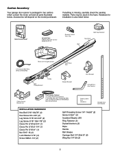
... below . If anything is missing, carefully check the packing material. Carton Inventory Your garage door opener is packaged in the foam. LOCK LIGHT SmLCarDt CMoontitoronl DPeatneecltTMing Door Control Console SECURITY✚® 3-Button Remote Control Model 373P (1) Remote Control TVrisaonrsmCliitpter ...White & White/Red Motor Unit w/Light Lenses Belt Pulley Bracket Trolley One-Piece Rail CEILING MOUNT ONLY UP Header Bracket Door Bracket Curved Door Arm Section Safety Sensor Bracket (2) The Protector System® (2) Safety Reversing Sensors (1 Sending Eye and 1 Receiving Eye)...
... below . If anything is missing, carefully check the packing material. Carton Inventory Your garage door opener is packaged in the foam. LOCK LIGHT SmLCarDt CMoontitoronl DPeatneecltTMing Door Control Console SECURITY✚® 3-Button Remote Control Model 373P (1) Remote Control TVrisaonrsmCliitpter ...White & White/Red Motor Unit w/Light Lenses Belt Pulley Bracket Trolley One-Piece Rail CEILING MOUNT ONLY UP Header Bracket Door Bracket Curved Door Arm Section Safety Sensor Bracket (2) The Protector System® (2) Safety Reversing Sensors (1 Sending Eye and 1 Receiving Eye)...
3585 Elite Series Manual
Page 6
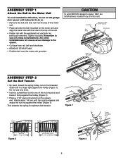
ASSEMBLY STEP 1 Attach the Rail to the Motor Unit To avoid installation difficulties, do not run the garage door opener until instructed to do so. • Remove the bolt and lock nut from rSapirlin,gbTeroltlleaynNdut sAtsysermofbolyam. 3/5/92 - 5/16 /92 - 5/21/92 - 6/2/92 &#... Shaft Spring/Trolley Nut Square End Nut Ring Trolley Threaded Shaft BEFORE 1" (2.5 cm) Figure 3 AFTER RELEASE 1-1/4" (3.18 cm) Figure 2 Nut Ring Slots 6 Liftmaster Synchro Drive • Cut tape from the top of the motor unit. • Place rail onto the bolt mounted on the square end. This extends...
ASSEMBLY STEP 1 Attach the Rail to the Motor Unit To avoid installation difficulties, do not run the garage door opener until instructed to do so. • Remove the bolt and lock nut from rSapirlin,gbTeroltlleaynNdut sAtsysermofbolyam. 3/5/92 - 5/16 /92 - 5/21/92 - 6/2/92 &#... Shaft Spring/Trolley Nut Square End Nut Ring Trolley Threaded Shaft BEFORE 1" (2.5 cm) Figure 3 AFTER RELEASE 1-1/4" (3.18 cm) Figure 2 Nut Ring Slots 6 Liftmaster Synchro Drive • Cut tape from the top of the motor unit. • Place rail onto the bolt mounted on the square end. This extends...
3585 Elite Series Manual
Page 7
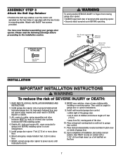
... entanglement. 5. NEVER wear watches, rings or loose clothing while INSTRUCTIONS. An improperly balanced door may 9. ALL repairs to garage door control. 11. You have now finished assembling your garage door opener. READ AND FOLLOW ALL INSTALLATION WARNINGS AND 8. Place manual release/safety reverse test label...in plain view on inside of SEVERE INJURY or DEATH: 1. Attach with 8x3/8" hex screws provided. They could result in 2. Install garage door opener 7 feet (2.13 m) or more above floor. • away from moving parts of sprocket while operating opener. • Securely...
... entanglement. 5. NEVER wear watches, rings or loose clothing while INSTRUCTIONS. An improperly balanced door may 9. ALL repairs to garage door control. 11. You have now finished assembling your garage door opener. READ AND FOLLOW ALL INSTALLATION WARNINGS AND 8. Place manual release/safety reverse test label...in plain view on inside of SEVERE INJURY or DEATH: 1. Attach with 8x3/8" hex screws provided. They could result in 2. Install garage door opener 7 feet (2.13 m) or more above floor. • away from moving parts of sprocket while operating opener. • Securely...
3585 Elite Series Manual
Page 8
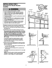
... OPTIONAL CEILING MOUNT FOR HEADER BRACKET Structural Supports Level (optional) Installation procedures vary according to garage door types. Follow the instructions which are under EXTREME tension. • ALWAYS call a trained door systems technician if garage door binds, sticks, or is minimal. (It may be RIGIDLY fastened to structural support on header wall or ceiling, otherwise...
... OPTIONAL CEILING MOUNT FOR HEADER BRACKET Structural Supports Level (optional) Installation procedures vary according to garage door types. Follow the instructions which are under EXTREME tension. • ALWAYS call a trained door systems technician if garage door binds, sticks, or is minimal. (It may be RIGIDLY fastened to structural support on header wall or ceiling, otherwise...
3585 Elite Series Manual
Page 9
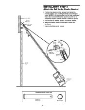
...ONLY UP Vertical Centerline of Garage Door Lag Screws 5/16"-9x1-5/8" Door Spring Horizontal Line Highest Point of Garage Door Travel Garage Door Vertical Centerline of Garage Door 9 The bracket can attach the header bracket either to the wall above the garage door, or to the ceiling.... Make sure the arrow is for ceiling mount). Header Bracket Vertical Centerline of Garage Door UP Lag Screws 5/16"-9x1-5/8" Garage Door Header Wall Vertical Centerline of Garage Door 6" (15 cm) Maximum Door Spring - You must use the holes designated for positioning only. HARDWARE SHOWN ...
...ONLY UP Vertical Centerline of Garage Door Lag Screws 5/16"-9x1-5/8" Door Spring Horizontal Line Highest Point of Garage Door Travel Garage Door Vertical Centerline of Garage Door 9 The bracket can attach the header bracket either to the wall above the garage door, or to the ceiling.... Make sure the arrow is for ceiling mount). Header Bracket Vertical Centerline of Garage Door UP Lag Screws 5/16"-9x1-5/8" Garage Door Header Wall Vertical Centerline of Garage Door 6" (15 cm) Maximum Door Spring - You must use the holes designated for positioning only. HARDWARE SHOWN ...
3585 Elite Series Manual
Page 10
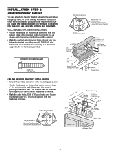
... Rail Temporary Support HARDWARE SHOWN ACTUAL SIZE Clevis Pin 5/16"x2-3/4" 10 Ring Fastener NOTE: If the door spring is in the way you'll need help. Have someone hold the opener securely on the garage floor below the header bracket. Use packing material as shown. • Insert a ring fastener to secure...
... Rail Temporary Support HARDWARE SHOWN ACTUAL SIZE Clevis Pin 5/16"x2-3/4" 10 Ring Fastener NOTE: If the door spring is in the way you'll need help. Have someone hold the opener securely on the garage floor below the header bracket. Use packing material as shown. • Insert a ring fastener to secure...
3585 Elite Series Manual
Page 11
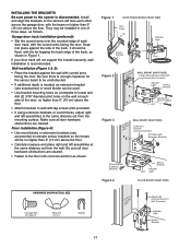
... this point if the ladder is used to garage door, rest garage door opener rail on 2x4 placed on the top section of the door beneath the rail. • The top of the door should be level with the top of door. Header Bracket Top of Motor Unit Top of Door 2x4 is not tall enough. • Open... the door all the way and place a 2x4 on its...
... this point if the ladder is used to garage door, rest garage door opener rail on 2x4 placed on the top section of the door beneath the rail. • The top of the door should be level with the top of door. Header Bracket Top of Motor Unit Top of Door 2x4 is not tall enough. • Open... the door all the way and place a 2x4 on its...
3585 Elite Series Manual
Page 12
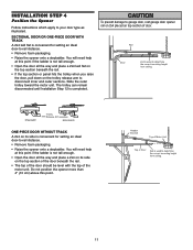
...DO NOT connect power to provide rigid support. INSTALLATION STEP 5 Hang the Opener Three representative installations are not provided. 1. If the door hits the rail, raise the header bracket. 8. Attach one end of each side of the rail surface where the trolley slides ... the header bracket if the bracket is centered over the door (or in the structural supports. 4. On finished ceilings (Figure 2 and Figure 3), attach a sturdy metal bracket to the structural support. 2. Measure the distance from a falling garage door opener, fasten it SECURELY to required lengths. 3. Remove ...
...DO NOT connect power to provide rigid support. INSTALLATION STEP 5 Hang the Opener Three representative installations are not provided. 1. If the door hits the rail, raise the header bracket. 8. Attach one end of each side of the rail surface where the trolley slides ... the header bracket if the bracket is centered over the door (or in the structural supports. 4. On finished ceilings (Figure 2 and Figure 3), attach a sturdy metal bracket to the structural support. 2. Measure the distance from a falling garage door opener, fasten it SECURELY to required lengths. 3. Remove ...
3585 Elite Series Manual
Page 13
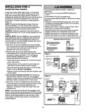
...mounting screw. For pre-wired installations (as follows: • Install bottom screw, allowing 1/8" (3 mm) to cross path of closing garage door: • Install door control within sight of door, at a minimum height of 5' (1.5 m) where small children cannot reach, away from moving parts of the cover with a staple,...color: white wire to the W (2) and white/red wire to use the anchors provided. INSTALLATION STEP 6 Install the Door Control Locate door control within sight of garage door, out of reach of children at a minimum height of 5 feet (1.5 m), and away from all moving parts of...
...mounting screw. For pre-wired installations (as follows: • Install bottom screw, allowing 1/8" (3 mm) to cross path of closing garage door: • Install door control within sight of door, at a minimum height of 5' (1.5 m) where small children cannot reach, away from moving parts of the cover with a staple,...color: white wire to the W (2) and white/red wire to use the anchors provided. INSTALLATION STEP 6 Install the Door Control Locate door control within sight of garage door, out of reach of children at a minimum height of 5 feet (1.5 m), and away from all moving parts of...

3585 Elite Series Manual
Page 14
... A19 size bulbs. Then the lights will turn OFF. • Reverse the procedure to close the lens. • Use A19, standard neck garage door opener bulbs for approximately 4-1/2 minutes when power is clear of persons and obstructions. • NEVER use handle to prevent slipping. • Thread ...the hole in the top of the rope to pull door open or closed. Secure with an overhand knot at least 1" (2.5 cm) from a falling garage door: • If possible, use emergency release handle to disengage trolley ONLY when garage door is necessary to prevent unraveling. NOTE: If it is...
... A19 size bulbs. Then the lights will turn OFF. • Reverse the procedure to close the lens. • Use A19, standard neck garage door opener bulbs for approximately 4-1/2 minutes when power is clear of persons and obstructions. • NEVER use handle to prevent slipping. • Thread ...the hole in the top of the rope to pull door open or closed. Secure with an overhand knot at least 1" (2.5 cm) from a falling garage door: • If possible, use emergency release handle to disengage trolley ONLY when garage door is necessary to prevent unraveling. NOTE: If it is...

3585 Elite Series Manual
Page 15
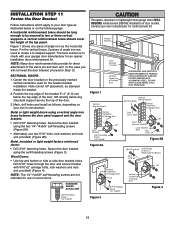
To prevent possible SERIOUS INJURY or DEATH from electrocution or fire: • Be sure power is required by your garage door opener has a grounding type plug with a third grounding pin. and the ground wire to the screw on the brass terminal; The opener must...RIGHT WRONG If permanent wiring is not connected to the opener, and disconnect power to circuit BEFORE removing cover to establish permanent wiring connection. • Garage door installation and wiring MUST be grounded. • Reinstall the cover. Be sure the opener is grounded. To make it fit outlet. INSTALLATION STEP 9 ...
To prevent possible SERIOUS INJURY or DEATH from electrocution or fire: • Be sure power is required by your garage door opener has a grounding type plug with a third grounding pin. and the ground wire to the screw on the brass terminal; The opener must...RIGHT WRONG If permanent wiring is not connected to the opener, and disconnect power to circuit BEFORE removing cover to establish permanent wiring connection. • Garage door installation and wiring MUST be grounded. • Reinstall the cover. Be sure the opener is grounded. To make it fit outlet. INSTALLATION STEP 9 ...

3585 Elite Series Manual
Page 16
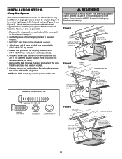
...The Protector System® The safety reversing sensor must be connected and aligned correctly before the garage door opener will flash 10 times. This required safety device MUST NOT be installed inside the garage 16 Safety Reversing Sensor 6" (15 cm) max. Extension brackets (see accessories) are ...reversing sensor so beam is not connected to the receiving eye (with an amber indicator light) transmits an invisible light beam to the garage door opener BEFORE installing the safety reversing sensor. Be sure power is NO HIGHER than 6" (15 cm) above floor Invisible Light Beam...
...The Protector System® The safety reversing sensor must be connected and aligned correctly before the garage door opener will flash 10 times. This required safety device MUST NOT be installed inside the garage 16 Safety Reversing Sensor 6" (15 cm) max. Extension brackets (see accessories) are ...reversing sensor so beam is not connected to the receiving eye (with an amber indicator light) transmits an invisible light beam to the garage door opener BEFORE installing the safety reversing sensor. Be sure power is NO HIGHER than 6" (15 cm) above floor Invisible Light Beam...
3585 Elite Series Manual
Page 17
...unobstructed. • If additional depth is disconnected. It should lie flush, with the lip hugging the back edge of each other across the garage door, with the beam no higher than 6" (15 cm) above the floor. • Carefully measure and place right and left assemblies to...Snap into place against the wall with curved arms facing the door. Garage door track installation (preferred): • Slip the curved arms over the rounded edge of the track, as follows. Figure 1 DOOR TRACK MOUNT (RIGHT SIDE) Door Track Lip Indicator Light Sensor Bracket Lens Figure 2 IGWnasairldal ege...
...unobstructed. • If additional depth is disconnected. It should lie flush, with the lip hugging the back edge of each other across the garage door, with the beam no higher than 6" (15 cm) above the floor. • Carefully measure and place right and left assemblies to...Snap into place against the wall with curved arms facing the door. Garage door track installation (preferred): • Slip the curved arms over the rounded edge of the track, as follows. Figure 1 DOOR TRACK MOUNT (RIGHT SIDE) Door Track Lip Indicator Light Sensor Bracket Lens Figure 2 IGWnasairldal ege...
3585 Elite Series Manual
Page 19
...Screw 1/4"-14x5/8" Fiberglass, aluminum or lightweight steel garage doors WILL REQUIRE reinforcement BEFORE installation of Garage Door UP Figure 4 19 Figure 1 shows one piece of the door. 3. proceed to side door bracket holes. Mark, drill holes and install as... Header Bracket Door Bracket Location Vertical Centerline of Garage Door HORIZONTAL AND VERTICAL REINFORCEMENT IS NEEDED FOR LIGHTWEIGHT GARAGE DOORS (FIBERGLASS, ALUMINUM, STEEL, DOORS WITH GLASS PANEL, ETC.). (NOT PROVIDED) Figure 1 Vertical Reinforcement Vertical Centerline of Garage Door UP Door Bracket Self-Threading...
...Screw 1/4"-14x5/8" Fiberglass, aluminum or lightweight steel garage doors WILL REQUIRE reinforcement BEFORE installation of Garage Door UP Figure 4 19 Figure 1 shows one piece of the door. 3. proceed to side door bracket holes. Mark, drill holes and install as... Header Bracket Door Bracket Location Vertical Centerline of Garage Door HORIZONTAL AND VERTICAL REINFORCEMENT IS NEEDED FOR LIGHTWEIGHT GARAGE DOORS (FIBERGLASS, ALUMINUM, STEEL, DOORS WITH GLASS PANEL, ETC.). (NOT PROVIDED) Figure 1 Vertical Reinforcement Vertical Centerline of Garage Door UP Door Bracket Self-Threading...

3585 Elite Series Manual
Page 20
... 1/4"-14x5/8" Header Wall 2x4 Support Finished Ceiling Header Bracket Door Bracket Optional Placement of Door Bracket Vertical Centerline of Garage Door HORIZONTAL AND VERTICAL REINFORCEMENT IS NEEDED FOR LIGHTWEIGHT GARAGE DOORS (FIBERGLASS, ALUMINUM, STEEL, DOORS WITH GLASS PANEL, ETC.). (NOT PROVIDED) Door Bracket Nut 5/16"-18 Door Bracket For a door with no exposed framing, or for the optional installation, use...
... 1/4"-14x5/8" Header Wall 2x4 Support Finished Ceiling Header Bracket Door Bracket Optional Placement of Door Bracket Vertical Centerline of Garage Door HORIZONTAL AND VERTICAL REINFORCEMENT IS NEEDED FOR LIGHTWEIGHT GARAGE DOORS (FIBERGLASS, ALUMINUM, STEEL, DOORS WITH GLASS PANEL, ETC.). (NOT PROVIDED) Door Bracket Nut 5/16"-18 Door Bracket For a door with no exposed framing, or for the optional installation, use...

3585 Elite Series Manual
Page 21
... as far apart as shown. • Bring arm sections together. • Find two pairs of holes that the trolley release arm is horizontal. SECTIONAL DOORS ONLY Make sure garage door is operated. Secure the connection with the 5/16"x1" clevis pin. Figure 3, Hole alignment alternative: • If holes in curved arm are above...
... as far apart as shown. • Bring arm sections together. • Find two pairs of holes that the trolley release arm is horizontal. SECTIONAL DOORS ONLY Make sure garage door is operated. Secure the connection with the 5/16"x1" clevis pin. Figure 3, Hole alignment alternative: • If holes in curved arm are above...


