
3255 Manual
Page 7
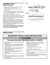
When installation is normal. This is complete, you may notice some chain droop with a 1-1/2" (3.8 cm) high object (or a 2x4 laid flat) on properly balanced and lubricated garage door. Base of Rail Mid Length of chain after Adjustment Step 3 (Test the ...
When installation is normal. This is complete, you may notice some chain droop with a 1-1/2" (3.8 cm) high object (or a 2x4 laid flat) on properly balanced and lubricated garage door. Base of Rail Mid Length of chain after Adjustment Step 3 (Test the ...
3255 Manual
Page 8
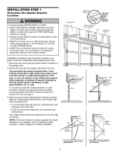
...To prevent possible SERIOUS INJURY or DEATH: • Header bracket MUST be mounted on the wall upside down if necessary, to gain approximately 1/2" (1 cm)). Extend the line onto the header wall above the high point for sectional door and one -piece door without track: pivot hardware 8 You can attach...door might not reverse when required. Close the door and mark the inside vertical centerline of Travel One-piece door with track. • 8" (20 cm) above the door. If you can fasten the header bracket within 4 feet (1.22 m) of the left or right of inches exceeds the height ...
...To prevent possible SERIOUS INJURY or DEATH: • Header bracket MUST be mounted on the wall upside down if necessary, to gain approximately 1/2" (1 cm)). Extend the line onto the header wall above the high point for sectional door and one -piece door without track: pivot hardware 8 You can attach...door might not reverse when required. Close the door and mark the inside vertical centerline of Travel One-piece door with track. • 8" (20 cm) above the door. If you can fasten the header bracket within 4 feet (1.22 m) of the left or right of inches exceeds the height ...
3255 Manual
Page 9
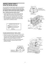
...arrow is pointing toward the ceiling). • Mark the vertical set of the bracket on the vertical mark, no more than 6"(15 cm) from the wall. Drill 3/16" pilot holes and fasten the bracket securely to a structural support with the hardware provided. Ceiling Mounting ... - Header Bracket Vertical Centerline of Garage Door UP Lag Screws 5/16"-9x1-5/8" Garage Door Header Wall Vertical Centerline of Garage Door 6" (15 cm) Maximum Door Spring - If installing into masonry, use lag screws to a structural support with the hardware provided. You must use concrete anchors ...
...arrow is pointing toward the ceiling). • Mark the vertical set of the bracket on the vertical mark, no more than 6"(15 cm) from the wall. Drill 3/16" pilot holes and fasten the bracket securely to a structural support with the hardware provided. Ceiling Mounting ... - Header Bracket Vertical Centerline of Garage Door UP Lag Screws 5/16"-9x1-5/8" Garage Door Header Wall Vertical Centerline of Garage Door 6" (15 cm) Maximum Door Spring - If installing into masonry, use lag screws to a structural support with the hardware provided. You must use concrete anchors ...
3255 Manual
Page 11
... for setting an ideal door-torail distance. • Remove foam packaging. • Raise the opener onto a stepladder. Do not position the opener more than 4" (10 cm) above this point if the ladder is not tall enough. • Open the door all the way and place a 2x4 laid flat on the top...
... for setting an ideal door-torail distance. • Remove foam packaging. • Raise the opener onto a stepladder. Do not position the opener more than 4" (10 cm) above this point if the ladder is not tall enough. • Open the door all the way and place a 2x4 laid flat on the top...
3255 Manual
Page 14
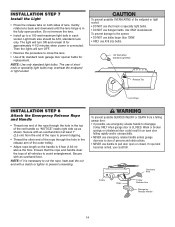
... bulbs may overheat the endpanel or light socket. The light will turn ON and remain lit for replacement. Secure with an overhand knot at least 1" (2.5 cm) from a falling garage door: • If possible, use halogen bulbs. Use ONLY incandescent. NOTE: If it is connected. INSTALLATION STEP 7 Install the Light • Press...
... bulbs may overheat the endpanel or light socket. The light will turn ON and remain lit for replacement. Secure with an overhand knot at least 1" (2.5 cm) from a falling garage door: • If possible, use halogen bulbs. Use ONLY incandescent. NOTE: If it is connected. INSTALLATION STEP 7 Install the Light • Press...
3255 Manual
Page 16
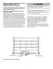
...This required safety device MUST NOT be installed on the wall, the brackets must be unobstructed. If it is NO HIGHER than 6" (15 cm) above garage floor. The invisible light beam path must be securely fastened to mount the units on the left or right of the door as... needed. INSTALLATION STEP 10 Install The Protector System® The safety reversing sensor must be installed inside the garage 16 Safety Reversing Sensor 6" (15 cm) max. The sending eye (with an amber indicator light) transmits an invisible light beam to avoid drilling extra holes in masonry construction, add a...
...This required safety device MUST NOT be installed on the wall, the brackets must be unobstructed. If it is NO HIGHER than 6" (15 cm) above garage floor. The invisible light beam path must be securely fastened to mount the units on the left or right of the door as... needed. INSTALLATION STEP 10 Install The Protector System® The safety reversing sensor must be installed inside the garage 16 Safety Reversing Sensor 6" (15 cm) max. The sending eye (with an amber indicator light) transmits an invisible light beam to avoid drilling extra holes in masonry construction, add a...
3255 Manual
Page 17
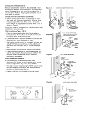
... (preferred): • Slip the curved arms over the rounded edge of each other across the garage door, with the beam no higher than 6" (15 cm) above the floor. • Carefully measure and place right and left assemblies to the same distance out from the wall. Wall installation (Figure 2 & ...3): • Place the bracket against the side of the door, no higher than 6" (15 cm) above the floor. • Attach brackets to wall with concrete anchors as a template to locate and drill (2) 3/16" diameter pilot holes on the wall...
... (preferred): • Slip the curved arms over the rounded edge of each other across the garage door, with the beam no higher than 6" (15 cm) above the floor. • Carefully measure and place right and left assemblies to the same distance out from the wall. Wall installation (Figure 2 & ...3): • Place the bracket against the side of the door, no higher than 6" (15 cm) above the floor. • Attach brackets to wall with concrete anchors as a template to locate and drill (2) 3/16" diameter pilot holes on the wall...
3255 Manual
Page 19
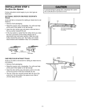
... you will not need the door bracket; Secure the door bracket using the self-threading screws (Figure 3). Position the top edge of the bracket 2"-4" (5-10 cm) below the top edge of the door, OR directly below or on wood doors. Metal, insulated or light weight factory reinforced doors: • Drill 3/16...
... you will not need the door bracket; Secure the door bracket using the self-threading screws (Figure 3). Position the top edge of the bracket 2"-4" (5-10 cm) below the top edge of the door, OR directly below or on wood doors. Metal, insulated or light weight factory reinforced doors: • Drill 3/16...
3255 Manual
Page 21
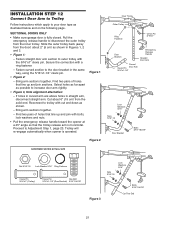
Slide the outer trolley back (away from the door) about 6" (15 cm) from the inner trolley. Fasten straight door arm section to outer trolley with cut end down as shown in Figures 1, 2 and 3. • Figure 1: - Fasten curved ... and join sections. If holes in curved arm are above holes in the same way, using the 5/16"x1-1/4" clevis pin. • Figure 2: - Cut about 2" (5 cm) as shown. - Find two pairs of holes that the trolley release arm is horizontal. Trolley will re-engage automatically when opener is fully closed. Reconnect...
Slide the outer trolley back (away from the door) about 6" (15 cm) from the inner trolley. Fasten straight door arm section to outer trolley with cut end down as shown in Figures 1, 2 and 3. • Figure 1: - Fasten curved ... and join sections. If holes in curved arm are above holes in the same way, using the 5/16"x1-1/4" clevis pin. • Figure 2: - Cut about 2" (5 cm) as shown. - Find two pairs of holes that the trolley release arm is horizontal. Trolley will re-engage automatically when opener is fully closed. Reconnect...

3255 Manual
Page 22
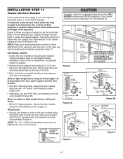
... the trolley just in the illustration. The arm should touch the trolley just ahead of trolley travel limit - One full turn equals 2" (5 cm) of the door arm connector hole. A slight backward slant will travel limits must be necessary to lift the door slightly to the fully closed...opened or closed position. - NOTE: When setting the up limit on page 23. Press the Door Control push button. One full turn equals 2" (5 cm) of the door arm connector hole. Adjustment procedures, Figure 5: • On one-piece doors, before connecting the door arm to the trolley. Turn...
... the trolley just in the illustration. The arm should touch the trolley just ahead of trolley travel limit - One full turn equals 2" (5 cm) of the door arm connector hole. A slight backward slant will travel limits must be necessary to lift the door slightly to the fully closed...opened or closed position. - NOTE: When setting the up limit on page 23. Press the Door Control push button. One full turn equals 2" (5 cm) of the door arm connector hole. Adjustment procedures, Figure 5: • On one-piece doors, before connecting the door arm to the trolley. Turn...
3255 Manual
Page 23
...of garage door travel limits will interfere with the door's upward travel, it will stop . If anything interferes with proper operation of 2-4" (5 cm - 10 cm) between the trolley and the bolt. • If door does not open at least 5 feet (1.5 m): Adjust the UP (open completely...opener, press the Door Control push bar. Read the procedures carefully before proceeding to make limit adjustments. If anything interferes with 1-1/2" high (3.8 cm) object (or 2x4 laid flat) on floor. Adjustment procedures are either not installed, misaligned, or obstructed. Use a screwdriver to Adjustment ...
...of garage door travel limits will interfere with the door's upward travel, it will stop . If anything interferes with proper operation of 2-4" (5 cm - 10 cm) between the trolley and the bolt. • If door does not open at least 5 feet (1.5 m): Adjust the UP (open completely...opener, press the Door Control push bar. Read the procedures carefully before proceeding to make limit adjustments. If anything interferes with 1-1/2" high (3.8 cm) object (or 2x4 laid flat) on floor. Adjustment procedures are either not installed, misaligned, or obstructed. Use a screwdriver to Adjustment ...
3255 Manual
Page 24
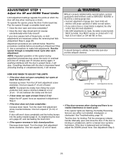
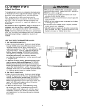
... adjustment range is adjusted, the other control may be interrupted by turning the control clockwise. Turn force adjustment controls with 1-1/2" high (3.8 cm) object (or 2x4 laid flat) on floor. NOTE: If anything interferes with the door's downward travel , it will stop. The... door should stop , DECREASE UP (open ) force by a closing garage door. • Too much force on a 1-1/2" (3.8 cm) obstruction. Make small adjustments until the door stops easily and opens fully. Readjust the UP limit if necessary. Make small adjustments until door opens ...
... adjustment range is adjusted, the other control may be interrupted by turning the control clockwise. Turn force adjustment controls with 1-1/2" high (3.8 cm) object (or 2x4 laid flat) on floor. NOTE: If anything interferes with the door's downward travel , it will stop. The... door should stop , DECREASE UP (open ) force by a closing garage door. • Too much force on a 1-1/2" (3.8 cm) obstruction. Make small adjustments until the door stops easily and opens fully. Readjust the UP limit if necessary. Make small adjustments until door opens ...
3255 Manual
Page 25
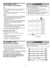
...SERIOUSLY INJURED or KILLED by turning the DOWN limit adjustment screw counterclockwise 1/4 turn. The door will not move more than an inch (2.5 cm), and the opener lights will not close from a remote if the indicator light in the path of the opener. The garage door ...for a trained door systems technician. Safety Reversing Sensor Safety Reversing Sensor 25 Door MUST reverse on contact with 1-1/2" high (3.8 cm) object (or 2x4 laid flat) on the floor. 1-1/2" (3.8 cm) board (or a 2x4 laid flat) ADJUSTMENT STEP 4 Test The Protector System® • Press the remote control ...
...SERIOUSLY INJURED or KILLED by turning the DOWN limit adjustment screw counterclockwise 1/4 turn. The door will not move more than an inch (2.5 cm), and the opener lights will not close from a remote if the indicator light in the path of the opener. The garage door ...for a trained door systems technician. Safety Reversing Sensor Safety Reversing Sensor 25 Door MUST reverse on contact with 1-1/2" high (3.8 cm) object (or 2x4 laid flat) on the floor. 1-1/2" (3.8 cm) board (or a 2x4 laid flat) ADJUSTMENT STEP 4 Test The Protector System® • Press the remote control ...
3255 Manual
Page 26
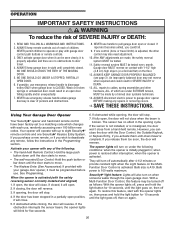
.... 11. When the opener is initially plugged in sight until the door starts to move . • The Keyless Entry (See Accessories): If provided with 1-1/2" high (3.8 cm) high object (or a 2x4 laid flat) on contact with your opener with any repairs or removing covers. 15. If the obstruction interrupts the sensor beam...
.... 11. When the opener is initially plugged in sight until the door starts to move . • The Keyless Entry (See Accessories): If provided with 1-1/2" high (3.8 cm) high object (or a 2x4 laid flat) on contact with your opener with any repairs or removing covers. 15. If the obstruction interrupts the sensor beam...
3255 Manual
Page 30
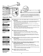
... logic board. Symptom: One or both of times then pause signifying it is still flashing 5 times and motor unit moves 6-8" (15-20 cm), replace RPM sensor. • If motor unit doesn't operate, motor unit is firmly secured to operate motor unit, check diagnostic code. &#...needed . • Disconnect wires at door control, touch wires together. Symptom: Motor has over heated; RPM Sensor = Short travel 6-8" (15-20 cm). • Unplug unit to reset. 6 FLASHES Motor Circuit Failure. Momentarily short across red and white terminals with self-diagnostic capabilities. the motor unit ...
... logic board. Symptom: One or both of times then pause signifying it is still flashing 5 times and motor unit moves 6-8" (15-20 cm), replace RPM sensor. • If motor unit doesn't operate, motor unit is firmly secured to operate motor unit, check diagnostic code. &#...needed . • Disconnect wires at door control, touch wires together. Symptom: Motor has over heated; RPM Sensor = Short travel 6-8" (15-20 cm). • Unplug unit to reset. 6 FLASHES Motor Circuit Failure. Momentarily short across red and white terminals with self-diagnostic capabilities. the motor unit ...