
3255 Manual
Page 2
... review 2 Preparing your garage door 3 Tools needed 3 Planning 4 Carton inventory 5 Hardware inventory 5 Assembly 6-7 Attach the rail to the motor unit 6 Attach the chain to the sprocket 6 Tighten the chain 7 Installation 7-22 Installation safety instructions 7 Determine the header bracket location 8 Install the header bracket 9 Attach the rail to the header bracket 10 Position...
... review 2 Preparing your garage door 3 Tools needed 3 Planning 4 Carton inventory 5 Hardware inventory 5 Assembly 6-7 Attach the rail to the motor unit 6 Attach the chain to the sprocket 6 Tighten the chain 7 Installation 7-22 Installation safety instructions 7 Determine the header bracket location 8 Install the header bracket 9 Attach the rail to the header bracket 10 Position...
3255 Manual
Page 4
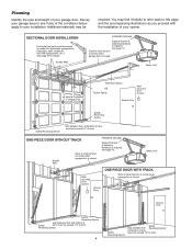
... Sensor Gap between floor Reversing Sensor and bottom of door must not exceed 1/4" (6 mm). ONE-PIECE DOOR WITHOUT TRACK Header Wall Slack in chain tension is normal when garage door is closed . Motor Unit Wallmounted Door Control Access Door ONE-PIECE DOOR WITH TRACK Slack in... chain tension is normal when garage door is required. SECTIONAL DOOR INSTALLATION Horizontal and vertical reinforcement is required. Access Door Safety Reversing Sensor Gap ...
... Sensor Gap between floor Reversing Sensor and bottom of door must not exceed 1/4" (6 mm). ONE-PIECE DOOR WITHOUT TRACK Header Wall Slack in chain tension is normal when garage door is closed . Motor Unit Wallmounted Door Control Access Door ONE-PIECE DOOR WITH TRACK Slack in... chain tension is normal when garage door is required. SECTIONAL DOOR INSTALLATION Horizontal and vertical reinforcement is required. Access Door Safety Reversing Sensor Gap ...
3255 Manual
Page 5
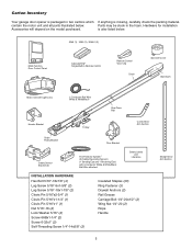
...in the foam. Hardware for installation Accessories will depend on the model purchased. Trolley One-Piece Rail Curved Door Arm Section Chain Pulley Bracket Door Bracket Safety Sensor Bracket (2) The Protector System® (2) Safety Reversing Sensors (1 Sending Eye and 1 Receiving.../Red? contain the motor unit and all parts illustrated below . 3245 (1), 3255 (1), 3255-2 (2) LOCK LIGHT Multi-Function Door Control Panel : SECURITY ® Single-Button Remote Control Remote Control Visor Clip Chain Sprocket Cover Styrofoam Motor Unit with 2-Conductor White & White/Black Bell Wire...
...in the foam. Hardware for installation Accessories will depend on the model purchased. Trolley One-Piece Rail Curved Door Arm Section Chain Pulley Bracket Door Bracket Safety Sensor Bracket (2) The Protector System® (2) Safety Reversing Sensors (1 Sending Eye and 1 Receiving.../Red? contain the motor unit and all parts illustrated below . 3245 (1), 3255 (1), 3255-2 (2) LOCK LIGHT Multi-Function Door Control Panel : SECURITY ® Single-Button Remote Control Remote Control Visor Clip Chain Sprocket Cover Styrofoam Motor Unit with 2-Conductor White & White/Black Bell Wire...
3255 Manual
Page 6
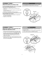
... bolts part way in the top of any other bolts will cause serious damage to the Sprocket and Install the Sprocket Cover • Position chain over sprocket. Use of the opener. Squeeze the cover slightly and insert the front tab in the slot on the trolley to garage door ...use ONLY those bolts/fasteners mounted in . USE ONLY THIS TYPE AND SIZE BOLT Rail Hole Washered Bolt 5/16"-18x1/2" Styrofoam ASSEMBLY STEP 2 Attach the Chain to door opener. • Align rail and styrofoam over the sprocket. If necessary, loosen the outer nut on the mounting plate. Washered Bolts 5/16"-...
... bolts part way in the top of any other bolts will cause serious damage to the Sprocket and Install the Sprocket Cover • Position chain over sprocket. Use of the opener. Squeeze the cover slightly and insert the front tab in the slot on the trolley to garage door ...use ONLY those bolts/fasteners mounted in . USE ONLY THIS TYPE AND SIZE BOLT Rail Hole Washered Bolt 5/16"-18x1/2" Styrofoam ASSEMBLY STEP 2 Attach the Chain to door opener. • Align rail and styrofoam over the sprocket. If necessary, loosen the outer nut on the mounting plate. Washered Bolts 5/16"-...
3255 Manual
Page 7
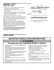
...installing opener to the installation section. Mount emergency release handle 6 feet (1.83 m) above the base of the rail at minimum height of chain after Adjustment Step 3 (Test the Safety Reversal System). Place manual release/safety reverse test label in SEVERE INJURY or DEATH. 3. Then ...systems technician BEFORE installing opener. 4. They could result in plain view on properly balanced and lubricated garage door. ASSEMBLY STEP 3 Tighten the Chain • Spin the inner nut and lock washer down the trolley threaded shaft, away from ALL moving parts of the door. 10. ...
...installing opener to the installation section. Mount emergency release handle 6 feet (1.83 m) above the base of the rail at minimum height of chain after Adjustment Step 3 (Test the Safety Reversal System). Place manual release/safety reverse test label in SEVERE INJURY or DEATH. 3. Then ...systems technician BEFORE installing opener. 4. They could result in plain view on properly balanced and lubricated garage door. ASSEMBLY STEP 3 Tighten the Chain • Spin the inner nut and lock washer down the trolley threaded shaft, away from ALL moving parts of the door. 10. ...
3255 Manual
Page 10
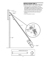
... bracket. • Align the bracket holes and join with a clevis pin as a protective base. Garage Door Ring Fastener Rail Header Bracket Clevis Pin 5/16"x2-3/4" Chain Pulley Bracket Rail Temporary Support HARDWARE SHOWN ACTUAL SIZE Clevis Pin 5/16"x2-3/4" 10 Ring Fastener Header Wall Header Bracket...
... bracket. • Align the bracket holes and join with a clevis pin as a protective base. Garage Door Ring Fastener Rail Header Bracket Clevis Pin 5/16"x2-3/4" Chain Pulley Bracket Rail Temporary Support HARDWARE SHOWN ACTUAL SIZE Clevis Pin 5/16"x2-3/4" 10 Ring Fastener Header Wall Header Bracket...
3255 Manual
Page 28
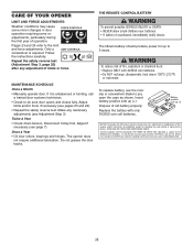
...°F) or incinerate. Disconnect trolley first. The lithium battery should produce power for changing the code setting or replacing the battery. Twice a Year • Check chain tension. Replace the battery with FCC and or Industry Canada rules (IC), adjustment or modifications of this device must accept any adjustment of operation. CARE...
...°F) or incinerate. Disconnect trolley first. The lithium battery should produce power for changing the code setting or replacing the battery. Twice a Year • Check chain tension. Replace the battery with FCC and or Industry Canada rules (IC), adjustment or modifications of this device must accept any adjustment of operation. CARE...
3255 Manual
Page 29
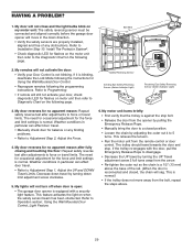
... door opener will sag. My motor unit hums briefly: • First verify that the trolley is reconnected and closed position. • Loosen the chain by turning down limit adjustment screw clockwise. 5. This relieves the tension. • Run the motor unit from the arrow. • Re-tighten... the outer nut so the chain is a 1/2" (13 mm) above . 29 My door reverses for Using the Wall-Mounted Door Control. • Reprogram remotes following page. 2. Weather ...
... door opener will sag. My motor unit hums briefly: • First verify that the trolley is reconnected and closed position. • Loosen the chain by turning down limit adjustment screw clockwise. 5. This relieves the tension. • Run the motor unit from the arrow. • Re-tighten... the outer nut so the chain is a 1/2" (13 mm) above . 29 My door reverses for Using the Wall-Mounted Door Control. • Reprogram remotes following page. 2. Weather ...
3255 Manual
Page 33
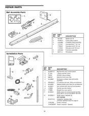
... bracket 3 41A3489 Complete trolley assembly 4 1707LM One-piece rail 7' (2.1 m) 1708LM One-piece rail 8' (2.4 m) 1710LM One-piece rail 10' (3 m) 5 41D3484 Full chain assembly 6 83A11-2 Rail grease 1 LOCK LIGHT 3 2 4 5 7 CEILING MOUNT ONLY UP NOTICE 6 10 11 12 8 9 KEY PART NO. NO. REPAIR PARTS Rail Assembly Parts 5 1 3 4 2 Installation Parts ...
... bracket 3 41A3489 Complete trolley assembly 4 1707LM One-piece rail 7' (2.1 m) 1708LM One-piece rail 8' (2.4 m) 1710LM One-piece rail 10' (3 m) 5 41D3484 Full chain assembly 6 83A11-2 Rail grease 1 LOCK LIGHT 3 2 4 5 7 CEILING MOUNT ONLY UP NOTICE 6 10 11 12 8 9 KEY PART NO. NO. REPAIR PARTS Rail Assembly Parts 5 1 3 4 2 Installation Parts ...


