1355 Manual
Page 2
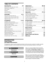
... To erase all codes 35 3-Button remotes 35 To add, reprogram or change a Keyless Entry PIN 36 Repair Parts 37-38 Rail assembly parts 37 Installation parts 37 Motor unit assembly parts 38 Accessories 39 Repair Parts and Service 40 Warranty 40 INTRODUCTION Safety Symbol and Signal Word Review This garage door opener has been...
... To erase all codes 35 3-Button remotes 35 To add, reprogram or change a Keyless Entry PIN 36 Repair Parts 37-38 Rail assembly parts 37 Installation parts 37 Motor unit assembly parts 38 Accessories 39 Repair Parts and Service 40 Warranty 40 INTRODUCTION Safety Symbol and Signal Word Review This garage door opener has been...
1355 Manual
Page 6
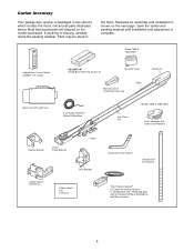
Save the carton and packing material until installation and adjustment is shown on the model purchased. Parts may be stuck in two cartons which contain the motor unit and all parts illustrated below. Model 1355 & 1345 ONLY Lighted Door Control Button w/6ABx1-1/2" screws SECURITY✚® Single-Button Remote Control (1) Sprocket Cover Remote Control...
Save the carton and packing material until installation and adjustment is shown on the model purchased. Parts may be stuck in two cartons which contain the motor unit and all parts illustrated below. Model 1355 & 1345 ONLY Lighted Door Control Button w/6ABx1-1/2" screws SECURITY✚® Single-Button Remote Control (1) Sprocket Cover Remote Control...
1355 Manual
Page 8
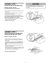
... shown. • Install the sprocket cover: Insert the back tab in the slot. ASSEMBLY STEP 1 Fasten the Rail to the Motor Unit MODELS 1355 AND 1345 ONLY (For Models 1356 and 1346 see page 9) • Remove the two washered bolts mounted in top of motor unit. • Position rail at an... angle to Assembly Step 5. Proceed to opener so one hole in . Use of the washered bolts part way in rail and motor unit line up. • Thread one of any other bolts will cause serious damage to the Sprocket and Install the...
... shown. • Install the sprocket cover: Insert the back tab in the slot. ASSEMBLY STEP 1 Fasten the Rail to the Motor Unit MODELS 1355 AND 1345 ONLY (For Models 1356 and 1346 see page 9) • Remove the two washered bolts mounted in top of motor unit. • Position rail at an... angle to Assembly Step 5. Proceed to opener so one hole in . Use of the washered bolts part way in rail and motor unit line up. • Thread one of any other bolts will cause serious damage to the Sprocket and Install the...

1355 Manual
Page 11
... Outer Nut Lock Washer Inner Nut ALL MODELS • Spin the inner nut and lock washer down the trolley threaded shaft, away from ALL moving parts of the door. 10. AS YOU TURN THE NUT, KEEP THE CHAIN FROM TWISTING. Install garage door opener ONLY on inside of garage door. 12...
... Outer Nut Lock Washer Inner Nut ALL MODELS • Spin the inner nut and lock washer down the trolley threaded shaft, away from ALL moving parts of the door. 10. AS YOU TURN THE NUT, KEEP THE CHAIN FROM TWISTING. Install garage door opener ONLY on inside of garage door. 12...
1355 Manual
Page 18
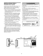
... Button Opener Terminal Screws BACK PANEL 1 2 3 9 1 7 3 5 KG 9 1 7 3 5 KG Antenna 18 Strip 1/4" (6 mm) of insulation from all moving parts of door. • NEVER permit children to operate or play with door control push buttons or remote control transmitters. • Activate door ONLY when it...DO NOT connect the power and operate the opener at this time. WARNING WARNING To prevent possible SERIOUS INJURY or DEATH from all moving parts of the door and door hardware. 1. Run the bell wire up the wall and across the ceiling to 1. 6. WARNING INSCTAALULTATIOIONN ...
... Button Opener Terminal Screws BACK PANEL 1 2 3 9 1 7 3 5 KG 9 1 7 3 5 KG Antenna 18 Strip 1/4" (6 mm) of insulation from all moving parts of door. • NEVER permit children to operate or play with door control push buttons or remote control transmitters. • Activate door ONLY when it...DO NOT connect the power and operate the opener at this time. WARNING WARNING To prevent possible SERIOUS INJURY or DEATH from all moving parts of the door and door hardware. 1. Run the bell wire up the wall and across the ceiling to 1. 6. WARNING INSCTAALULTATIOIONN ...

1355 Manual
Page 21
... indicator light). above garage floor. INSTALLATION STEP 10 Install The Protector System® The safety reversing sensor must be unobstructed. If it is necessary. No part of the door as long as the wall framing. WARNING Be sure power is closing , the door will stop and reverse to mount the units...
... indicator light). above garage floor. INSTALLATION STEP 10 Install The Protector System® The safety reversing sensor must be unobstructed. If it is necessary. No part of the door as long as the wall framing. WARNING Be sure power is closing , the door will stop and reverse to mount the units...

1355 Manual
Page 33
... may be frozen to Comply with a piece of motor unit extends fully downward. • Some installations may be broken. THERE ARE NO OTHER USER SERVICEABLE PARTS. The door may have tripped the overload protector in living quarters of home: • If operational noise is swallowed, immediately notify doctor. Remove any necessary...
... may be frozen to Comply with a piece of motor unit extends fully downward. • Some installations may be broken. THERE ARE NO OTHER USER SERVICEABLE PARTS. The door may have tripped the overload protector in living quarters of home: • If operational noise is swallowed, immediately notify doctor. Remove any necessary...

1355 Manual
Page 37
...41A4813 Chain pulley bracket 6 3 41A3489 Complete trolley assembly 4 1707LM One-piece rail 5 41D3484 Full chain assembly 6 83A11 Rail grease Installation Parts 1 5 NOTICE 12 3 6 2 7 CEILING MOUNT ONLY UP 8 10 9 11 4 KEY PART NO. white & white/red 7 41A4353 Header bracket w/clevis pin & fastener 8 41A5047 Door bracket w/clevis pin & fastener 9 41A5034 ...12 41A5266-1 Safety sensor brackets (2) Not shown 41A2770-6 Installation hardware bag (see page 7). 114A3072 Owner's manual 114A3072SP Owner's manual - REPAIR PARTS Rail Assembly Parts 5 1 3 4 2 KEY PART NO. NO.
...41A4813 Chain pulley bracket 6 3 41A3489 Complete trolley assembly 4 1707LM One-piece rail 5 41D3484 Full chain assembly 6 83A11 Rail grease Installation Parts 1 5 NOTICE 12 3 6 2 7 CEILING MOUNT ONLY UP 8 10 9 11 4 KEY PART NO. white & white/red 7 41A4353 Header bracket w/clevis pin & fastener 8 41A5047 Door bracket w/clevis pin & fastener 9 41A5034 ...12 41A5266-1 Safety sensor brackets (2) Not shown 41A2770-6 Installation hardware bag (see page 7). 114A3072 Owner's manual 114A3072SP Owner's manual - REPAIR PARTS Rail Assembly Parts 5 1 3 4 2 KEY PART NO. NO.
1355 Manual
Page 38
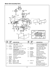
Motor Unit Assembly Parts 1 2 20 1A 2A 4 3 16 19 18 17 3 8 10 9 5 67 16 15 14 12 11 13 (Down) Contact Brown Wire Drive Gear UP DN LIMIT SWITCH ASSY. DESCRIPTION 1 41A4208-2 Chain spreader w/screws (1356, 1346) 1A 31D380 Sprocket cover (1355, 1345) 2 41C4206 Gear and sprocket ... 6 175B88 Light socket 7 108D36-2 Lens 8 30B532 Capacitor - 1/2HP 30B533 Capacitor - 1/3HP 9 12A373 Capacitor bracket 10 41A3150 Terminal block w/screws KEY PART NO. Complete with : Motor, worm, bracket, bearing assembly, RPM sensor. 12 41A3583-11 41A3583-15 13 41A2818 Cover 1/2HP (1356, 1355) Cover 1/3HP...
Motor Unit Assembly Parts 1 2 20 1A 2A 4 3 16 19 18 17 3 8 10 9 5 67 16 15 14 12 11 13 (Down) Contact Brown Wire Drive Gear UP DN LIMIT SWITCH ASSY. DESCRIPTION 1 41A4208-2 Chain spreader w/screws (1356, 1346) 1A 31D380 Sprocket cover (1355, 1345) 2 41C4206 Gear and sprocket ... 6 175B88 Light socket 7 108D36-2 Lens 8 30B532 Capacitor - 1/2HP 30B533 Capacitor - 1/3HP 9 12A373 Capacitor bracket 10 41A3150 Terminal block w/screws KEY PART NO. Complete with : Motor, worm, bracket, bearing assembly, RPM sensor. 12 41A3583-11 41A3583-15 13 41A2818 Cover 1/2HP (1356, 1355) Cover 1/3HP...

1355 Manual
Page 40
..., and you call. All Rights Reserved SIMPLY DIAL OUR TOLL FREE NUMBER: 1-800-528-2817 www.liftmaster.com For professional installation, parts and service, contact your compliance with any product returned for models 1346 & 1345 from state to you will void this product. HOW TO ORDER REPAIR... YEARS) FOR MODELS 1356 & 1355 AND 24 MONTHS (2 YEARS) FOR MODELS 1346 & 1345 LIMITED WARRANTY PERIOD FOR THE MOTOR], AND NO IMPLIED WARRANTIES WILL EXIST OR APPLY AFTER SUCH PERIOD. LIFTMASTER® SERVICE IS ON CALL OUR LARGE SERVICE ORGANIZATION SPANS AMERICA INSTALLATION AND SERVICE INFORMATION IS...
..., and you call. All Rights Reserved SIMPLY DIAL OUR TOLL FREE NUMBER: 1-800-528-2817 www.liftmaster.com For professional installation, parts and service, contact your compliance with any product returned for models 1346 & 1345 from state to you will void this product. HOW TO ORDER REPAIR... YEARS) FOR MODELS 1356 & 1355 AND 24 MONTHS (2 YEARS) FOR MODELS 1346 & 1345 LIMITED WARRANTY PERIOD FOR THE MOTOR], AND NO IMPLIED WARRANTIES WILL EXIST OR APPLY AFTER SUCH PERIOD. LIFTMASTER® SERVICE IS ON CALL OUR LARGE SERVICE ORGANIZATION SPANS AMERICA INSTALLATION AND SERVICE INFORMATION IS...


