
User's Guide (7.1 MB)
Page 263
...cartridge and fuser cleaner, clean the printer, and replace the charge roll. If you purchase your maintenance kit directly from worn parts. For your printer. The Lexmark maintenance kit part numbers are: Description Volts/Watts 115V, 750W 220V, 750W Optra S 2455 99A0500 ...99A0503 Maintaining Your Printer 247 Replacement of your printer. Optra S 2455 displays an 80 Scheduled Maintenance message, after you have...
...cartridge and fuser cleaner, clean the printer, and replace the charge roll. If you purchase your maintenance kit directly from worn parts. For your printer. The Lexmark maintenance kit part numbers are: Description Volts/Watts 115V, 750W 220V, 750W Optra S 2455 99A0500 ...99A0503 Maintaining Your Printer 247 Replacement of your printer. Optra S 2455 displays an 80 Scheduled Maintenance message, after you have...

User's Guide (7.1 MB)
Page 365
... (19.1 kg) 17.8 in . (482 mm x 445 mm) Duty Cycle Feature Duty cycle Optra S 1255 Up to 35,000 pages per month Optra S 1625 Up to 65,000 pages per month Optra S 1855 Up to 65,000 pages per month Optra S 2455 Up to 100,000 pages per month Supplies Supply Toner cartridges Charge roll... kit Label fuser cleaner Description 7.5K and 17.6K (at about 5% coverage) replacement toner cartridges...
... (19.1 kg) 17.8 in . (482 mm x 445 mm) Duty Cycle Feature Duty cycle Optra S 1255 Up to 35,000 pages per month Optra S 1625 Up to 65,000 pages per month Optra S 1855 Up to 65,000 pages per month Optra S 2455 Up to 100,000 pages per month Supplies Supply Toner cartridges Charge roll... kit Label fuser cleaner Description 7.5K and 17.6K (at about 5% coverage) replacement toner cartridges...

Service Manual
Page 6
... Upper Front Cover Hinge Assembly 4-61 Upper Front Cover Interlock Switch Assembly 4-62 Connector Locations 5-1 Low Voltage Power Supply 5-1 High Voltage Power Supply 5-3 Engine Board 5-4 Fuser Board 5-11 Interconnect Board 5-14 Envelope Option Board 5-17 Duplex Option Board 5-19 Autoconnect - Top 5-21 Output Expander Control Board - Level 2 DC Motor . . . . 5-24 Preventive...
... Upper Front Cover Hinge Assembly 4-61 Upper Front Cover Interlock Switch Assembly 4-62 Connector Locations 5-1 Low Voltage Power Supply 5-1 High Voltage Power Supply 5-3 Engine Board 5-4 Fuser Board 5-11 Interconnect Board 5-14 Envelope Option Board 5-17 Duplex Option Board 5-19 Autoconnect - Top 5-21 Output Expander Control Board - Level 2 DC Motor . . . . 5-24 Preventive...

Service Manual
Page 47
... Code CRC Failure 88 Toner Low Explanation The operator panel displays this message at this message. The microcode data is necessary to replace the fuser assembly, transfer roller, compensator pick-rolls and charge roll at each 250K page count interval. User Line 2 Messages If none of the ...It is discarded and must be programmed in the following actions can be taken: Press Menu> or Press Go to "Scheduled Maintenance (2420/2450/2455/ 3455)" on page 6-2. For more information, go to clear the message. This error displays when the microcode to clear this interval to maintain ...
... Code CRC Failure 88 Toner Low Explanation The operator panel displays this message at this message. The microcode data is necessary to replace the fuser assembly, transfer roller, compensator pick-rolls and charge roll at each 250K page count interval. User Line 2 Messages If none of the ...It is discarded and must be programmed in the following actions can be taken: Press Menu> or Press Go to "Scheduled Maintenance (2420/2450/2455/ 3455)" on page 6-2. For more information, go to clear the message. This error displays when the microcode to clear this interval to maintain ...

Service Manual
Page 51
...option elevator tray moves to warm up from a cold start than a warm start. 7. The main drive motor turns on the display. Models 2420, 2450 2455 and 3455 only - Diagnostic Information 2-24 The operator panel displays one and a half row of the base printer by observing the following: 1. The exit... turn the printer On, it performs a Power-On Self Test. The auxiliary fan turns on . 2. The duplex option is powered off. 13. The fuser takes longer to the uppermost position if installed. - The developer drive assembly drives the developer shaft in the toner cartridge. 10. The LED comes on...
...option elevator tray moves to warm up from a cold start than a warm start. 7. The main drive motor turns on the display. Models 2420, 2450 2455 and 3455 only - Diagnostic Information 2-24 The operator panel displays one and a half row of the base printer by observing the following: 1. The exit... turn the printer On, it performs a Power-On Self Test. The auxiliary fan turns on . 2. The duplex option is powered off. 13. The fuser takes longer to the uppermost position if installed. - The developer drive assembly drives the developer shaft in the toner cartridge. 10. The LED comes on...

Service Manual
Page 52
...2455/ 3455) fails to the "Operator Panel Service Check" on page 2-86. Dead Machine Operator Panel - Operator Panel continuously displays all diamonds - 5 beeps and does not complete POST. No Duplex Option installed. Black page Print quality - Go to run or is blank. Go to the "Fuser...Paper Feed Service Check" on page 2-74. Display is noisy. Paper jams at exit of Redrive Assembly - Print quality - Duplex Option installed Fuser Solenoid (Models 1620/1650/2420/2450/ 3455)fails to "Print Quality - Go to the "Auxiliary Fan Service Check" on page 2-35. ...
...2455/ 3455) fails to the "Operator Panel Service Check" on page 2-86. Dead Machine Operator Panel - Operator Panel continuously displays all diamonds - 5 beeps and does not complete POST. No Duplex Option installed. Black page Print quality - Go to run or is blank. Go to the "Fuser...Paper Feed Service Check" on page 2-74. Display is noisy. Paper jams at exit of Redrive Assembly - Print quality - Duplex Option installed Fuser Solenoid (Models 1620/1650/2420/2450/ 3455)fails to "Print Quality - Go to the "Auxiliary Fan Service Check" on page 2-35. ...

Service Manual
Page 78
... engine board. 3. A level I engine board require a envelope conditioner cable and no jumpers on the engine board. 2. The solenoid is in models 3455, 2455, 2450, 2420, 1855, 1650, 1625 and 1620 and the World Trade printer model 2450. A level II engine board can result to JP2-2 on the engine... board. 2-51 4059 Service Manual A level II fuser board and level II engine board require jumpers at locations JP1-2 to JP1-3 and JP2-2 to identify the level boards installed in configuration 2. A different...
... engine board. 3. A level I engine board require a envelope conditioner cable and no jumpers on the engine board. 2. The solenoid is in models 3455, 2455, 2450, 2420, 1855, 1650, 1625 and 1620 and the World Trade printer model 2450. A level II engine board can result to JP2-2 on the engine... board. 2-51 4059 Service Manual A level II fuser board and level II engine board require jumpers at locations JP1-2 to JP1-3 and JP2-2 to identify the level boards installed in configuration 2. A different...

Service Manual
Page 161
... On or Off to maintain the correct fuser temperature. 4059-XXX the hot roll increases. The thermistor is 270 degrees C while printing at 600 dpi and 170 degrees C while printing at 1200 dpi. The model 2420, 2450 and 2455 printer fuser temperature is set to J2-6 and J2-7 on the model... 2420, 2450, 2455, 3455, 1620, 1625, 1650 and 1855. J2-6 (TEMPIN+) and J2-7 (TEMPIN-) are assuming the...
... On or Off to maintain the correct fuser temperature. 4059-XXX the hot roll increases. The thermistor is 270 degrees C while printing at 600 dpi and 170 degrees C while printing at 1200 dpi. The model 2420, 2450 and 2455 printer fuser temperature is set to J2-6 and J2-7 on the model... 2420, 2450, 2455, 3455, 1620, 1625, 1650 and 1855. J2-6 (TEMPIN+) and J2-7 (TEMPIN-) are assuming the...

Service Manual
Page 166
...of curl of some printed media thus improving media stacking in the output bin. 1. Select EP SETUP from the Diagnostic Menu. 3. Printer Model 2420/2450/2455 1620/1625/1650/1855 3455 Solenoid Air Gap 4.4 mm (.170 inch) 3.9 mm (.153 inch) 4.8 mm (.153 inch) Gap Adjustment The gap ...no effect when printing in the printer. It may take several copies of the media that displays a curl problem. 4059-XXX Fuser Solenoid Adjustment Perform the fuser solenoid adjustment whenever you to increase the minimum gap between the rear of the solenoid stator and the solenoid armature. Enter the...
...of curl of some printed media thus improving media stacking in the output bin. 1. Select EP SETUP from the Diagnostic Menu. 3. Printer Model 2420/2450/2455 1620/1625/1650/1855 3455 Solenoid Air Gap 4.4 mm (.170 inch) 3.9 mm (.153 inch) 4.8 mm (.153 inch) Gap Adjustment The gap ...no effect when printing in the printer. It may take several copies of the media that displays a curl problem. 4059-XXX Fuser Solenoid Adjustment Perform the fuser solenoid adjustment whenever you to increase the minimum gap between the rear of the solenoid stator and the solenoid armature. Enter the...

Service Manual
Page 187
Remove the inner EMC shield. 3. Disconnect the auxiliary fan cable from the engine board at connector J7. 5. Repair Information 4-24 Remove the fuser wiper cover. 4. Note the routing of the auxiliary fan cable (A) and remove the fan (B). 4059-XXX Fans Auxiliary Fan (Models 2420/2450/2455/3455) 1. Remove the right cover. 2.
Remove the inner EMC shield. 3. Disconnect the auxiliary fan cable from the engine board at connector J7. 5. Repair Information 4-24 Remove the fuser wiper cover. 4. Note the routing of the auxiliary fan cable (A) and remove the fan (B). 4059-XXX Fans Auxiliary Fan (Models 2420/2450/2455/3455) 1. Remove the right cover. 2.

Service Manual
Page 230
4059-XXX Connector Pin No. J5 Printhead 1 2 3 4 5 6 7 8 9 10 J6 Output Level Sensor 1 2 3 4 5 J7 Auxiliary Fan 1 (Model 2420/2450/2455/ 3455) 2 J8 Printhead HYSNC 1 2 3 4 J9 Fuser Inductor Sense 1 WT 2450 Only 2 Signal LENA* Ground LAOJ* Ground LASERPWM +5 V dc Ground Video* Ground Ground Ground Ground Opt2 Opt1 +5 V dc CRFANONn Ground Ground HSYNC* Ground +5 V dc FISENSEn Ground 5-5 4059 Service Manual
4059-XXX Connector Pin No. J5 Printhead 1 2 3 4 5 6 7 8 9 10 J6 Output Level Sensor 1 2 3 4 5 J7 Auxiliary Fan 1 (Model 2420/2450/2455/ 3455) 2 J8 Printhead HYSNC 1 2 3 4 J9 Fuser Inductor Sense 1 WT 2450 Only 2 Signal LENA* Ground LAOJ* Ground LASERPWM +5 V dc Ground Video* Ground Ground Ground Ground Opt2 Opt1 +5 V dc CRFANONn Ground Ground HSYNC* Ground +5 V dc FISENSEn Ground 5-5 4059 Service Manual

Service Manual
Page 239
4059-XXX Interconnect Board Connector J1 Fuser Solenoid (Model1620/1625/ 1650/1855/2420/2450/ 2455) J2 LVPS J3 LVPS J4 Autoconnect Top (Model1620/1625/ 1650/1855/2420/2450/ 2455) Pin No. 1 2 1 2 3 4 5 6 7 8 9 10 1 2 3 4 5 6 7 8 1 2 3 4 Signal +42 V dc Ground +42 V dc Heaton Xeroxing +24 V dc +24 V dc +24 V dc Ground Ground Ground Ground Ground Ground Ground Ground +5 V dc +5 V dc +5 V dc +5 V dc +24 V dc Ground +5 V dc Fused Ground Connector Locations 5-14
4059-XXX Interconnect Board Connector J1 Fuser Solenoid (Model1620/1625/ 1650/1855/2420/2450/ 2455) J2 LVPS J3 LVPS J4 Autoconnect Top (Model1620/1625/ 1650/1855/2420/2450/ 2455) Pin No. 1 2 1 2 3 4 5 6 7 8 9 10 1 2 3 4 5 6 7 8 1 2 3 4 Signal +42 V dc Ground +42 V dc Heaton Xeroxing +24 V dc +24 V dc +24 V dc Ground Ground Ground Ground Ground Ground Ground Ground +5 V dc +5 V dc +5 V dc +5 V dc +24 V dc Ground +5 V dc Fused Ground Connector Locations 5-14

Service Manual
Page 252
... are available as a maintenance kit with the following part numbers: 99A0290 - 100V/750W 2450 99A0500 - 115V/750W 2420/2450/2455 99A0503 - 220V/750W 2420/2450/2455 99A0823 - 115V/750W 3455 99A0824 - 220V/750W 3455 After replacing the kit, the maintenance count must be reset to zero to..." message. 4059-XXX Scheduled Maintenance (2420/2450/2455/3455) The operator panel displays the message "80 Scheduled Maintenance" at this interval to maintain the print quality and reliability of the printer. It is necessary to replace the fuser assembly, transfer roller, compensator pick-rolls and charge...
... are available as a maintenance kit with the following part numbers: 99A0290 - 100V/750W 2450 99A0500 - 115V/750W 2420/2450/2455 99A0503 - 220V/750W 2420/2450/2455 99A0823 - 115V/750W 3455 99A0824 - 220V/750W 3455 After replacing the kit, the maintenance count must be reset to zero to..." message. 4059-XXX Scheduled Maintenance (2420/2450/2455/3455) The operator panel displays the message "80 Scheduled Maintenance" at this interval to maintain the print quality and reliability of the printer. It is necessary to replace the fuser assembly, transfer roller, compensator pick-rolls and charge...
Service Manual
Page 255
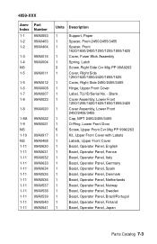
Blank 1 Cover Assembly, Lower Front 1250/1255/1620/1625/1650/1855/2420 1 Cover Assembly, Lower Front 2450/2455/3455 1 Cap, MPT 2450/2455/3455 1 O-Ring, Lower Front Door 5 Screw, Upper Front Cvr Mtg PP 99A0263 1 Kit, Upper Front Cover with Labels 1 Labels, ...99A0632 99A0633 99A0634 99A0535 99A0536 99A0537 99A0538 99A0539 99A0540 99A0541 Units Description 1 Support, Paper 1 Spacer, Front 2450/2455/3455 1 Spacer, Front 1620/1650/2420/1250/1255/1855/1625 1 Cover, Fuser Wick Assembly 1 Spring, Latch 3 Screw, Right Side Cvr Mtg PP 99A0263 1 Cover, RIght Side 1250...
Blank 1 Cover Assembly, Lower Front 1250/1255/1620/1625/1650/1855/2420 1 Cover Assembly, Lower Front 2450/2455/3455 1 Cap, MPT 2450/2455/3455 1 O-Ring, Lower Front Door 5 Screw, Upper Front Cvr Mtg PP 99A0263 1 Kit, Upper Front Cover with Labels 1 Labels, ...99A0632 99A0633 99A0634 99A0535 99A0536 99A0537 99A0538 99A0539 99A0540 99A0541 Units Description 1 Support, Paper 1 Spacer, Front 2450/2455/3455 1 Spacer, Front 1620/1650/2420/1250/1255/1855/1625 1 Cover, Fuser Wick Assembly 1 Spring, Latch 3 Screw, Right Side Cvr Mtg PP 99A0263 1 Cover, RIght Side 1250...

Service Manual
Page 279
...-8 99A0833 99A0562 99A0563 99A0149 99A0832 99A0144 Units Description 1 Fuser Assembly w/100V 750W Lamp 2420/2450/2455 1 Fuser Assembly w/115V 750W Lamp 2420/2450/2455 1 Fuser Assembly w/220V 750W Lamp 2420/2450/2455 1 Fuser Assembly w/100V 500W Lamp 1620/1650/1855/1625 1 Fuser Assembly w/115V 500W Lamp 1620/1650/1855/1625 1 Fuser Assembly w/220V 500W Lamp 1620/1650/1855/1625...
...-8 99A0833 99A0562 99A0563 99A0149 99A0832 99A0144 Units Description 1 Fuser Assembly w/100V 750W Lamp 2420/2450/2455 1 Fuser Assembly w/115V 750W Lamp 2420/2450/2455 1 Fuser Assembly w/220V 750W Lamp 2420/2450/2455 1 Fuser Assembly w/100V 500W Lamp 1620/1650/1855/1625 1 Fuser Assembly w/115V 500W Lamp 1620/1650/1855/1625 1 Fuser Assembly w/220V 500W Lamp 1620/1650/1855/1625...

Service Manual
Page 281
..., Hot Roll 2 Bellcrank, Backup Roll 1250/1255 2 Bellcrank, Backup Roll 1620/1650/1855/1625 2 Bellcrank, Backup Roll 2420/2450/2455 1 Bellcrank, Backup Roll 3455 1 Guide, Fuser Entry 1620/1650/2420/2450/2455/1855/1625/3455 1 Guide, Fuser Entry 1250/1255 2 Spring, Backup Roll Bellcrank 1250/1255 2 Spring, Backup Roll Bellcrank 1620/1650/2420/2450...
..., Hot Roll 2 Bellcrank, Backup Roll 1250/1255 2 Bellcrank, Backup Roll 1620/1650/1855/1625 2 Bellcrank, Backup Roll 2420/2450/2455 1 Bellcrank, Backup Roll 3455 1 Guide, Fuser Entry 1620/1650/2420/2450/2455/1855/1625/3455 1 Guide, Fuser Entry 1250/1255 2 Spring, Backup Roll Bellcrank 1250/1255 2 Spring, Backup Roll Bellcrank 1620/1650/2420/2450...

Service Manual
Page 299
... Assembly, Envelope Conditioner 1620/1625/1650/1855/2420/2450/2455/3455 1 Board Assembly, Fuser w/o Driver 1250/1255 1 Board Assembly, Fuser with Driver 1620/1625/1650/1855/2420/2450/2455 1 Board Assembly, Fuser 3455 1 Cover, Fuser Assembly with Thermistor, Thermal Fuse and RH Fuser Lamp Contact Assembly 1 Sensor, Narrow Media 1 Cable, Fuser D.C. 1 Cable, Fuser A.C. 1 Cable, Mirror Motor Parts Catalog 7-47
... Assembly, Envelope Conditioner 1620/1625/1650/1855/2420/2450/2455/3455 1 Board Assembly, Fuser w/o Driver 1250/1255 1 Board Assembly, Fuser with Driver 1620/1625/1650/1855/2420/2450/2455 1 Board Assembly, Fuser 3455 1 Cover, Fuser Assembly with Thermistor, Thermal Fuse and RH Fuser Lamp Contact Assembly 1 Sensor, Narrow Media 1 Cable, Fuser D.C. 1 Cable, Fuser A.C. 1 Cable, Mirror Motor Parts Catalog 7-47

Service Manual
Page 344
...5-21 B Base Sensor Test 3-17 Button Test 3-9 C Connector Locations Autoconnect 5-21 Duplex Option Board 5-19 Engine Board 5-4 Envelope Option Board 5-17 Fuser Board 5-11 High Voltage Power Supply 5-3 Interconnect Board 5-14 LVPS 5-1 Output Expander Control BoardLevel 1 Stepper Motor 5-22 Output Expander Control BoardLevel 2 DC...3-15 Output Bin X Sensor Test 3-16 Print Registration 3-18 Print Tests 3-22 Printer Setup 3-19 Maintenance Page Count (2420/ 2450/2455/3455) 3-20 Restore EP Factory Defaults 3-21 Setting Configuration ID 3-20 Setting the Page Count 3-19 Viewing the Permanent Page Count 3-...
...5-21 B Base Sensor Test 3-17 Button Test 3-9 C Connector Locations Autoconnect 5-21 Duplex Option Board 5-19 Engine Board 5-4 Envelope Option Board 5-17 Fuser Board 5-11 High Voltage Power Supply 5-3 Interconnect Board 5-14 LVPS 5-1 Output Expander Control BoardLevel 1 Stepper Motor 5-22 Output Expander Control BoardLevel 2 DC...3-15 Output Bin X Sensor Test 3-16 Print Registration 3-18 Print Tests 3-22 Printer Setup 3-19 Maintenance Page Count (2420/ 2450/2455/3455) 3-20 Restore EP Factory Defaults 3-21 Setting Configuration ID 3-20 Setting the Page Count 3-19 Viewing the Permanent Page Count 3-...

Service Manual
Page 345
...LVPS Connectors 5-1 M Maintenance Approach 1-5 Maintenance Page Count (2420/2450/ 2455/3455) 3-20 Maintenance, Preventive 6-1 Maintenance, Scheduled (Model 2420/ 2450/2455/3455) 6-2 Messages Check Device Connection Messages 2-22 Service Error Codes ...2-2 User Error Messages 2-16 User Line 2 Link Messages 2-22 User Line 2 Messages 2-20 User Status Messages 2-12 P Parallel Wrap Test 3-11 Parts Catalog 7-1 Charging 7-34 Covers 7-2 Developer Drive 7-24 Duplex 7-60 Electronics 7-36 Envelope Feeder 7-70 Frame 7-6 Fuser...
...LVPS Connectors 5-1 M Maintenance Approach 1-5 Maintenance Page Count (2420/2450/ 2455/3455) 3-20 Maintenance, Preventive 6-1 Maintenance, Scheduled (Model 2420/ 2450/2455/3455) 6-2 Messages Check Device Connection Messages 2-22 Service Error Codes ...2-2 User Error Messages 2-16 User Line 2 Link Messages 2-22 User Line 2 Messages 2-20 User Status Messages 2-12 P Parallel Wrap Test 3-11 Parts Catalog 7-1 Charging 7-34 Covers 7-2 Developer Drive 7-24 Duplex 7-60 Electronics 7-36 Envelope Feeder 7-70 Frame 7-6 Fuser...

Service Manual
Page 346
... Switch 4-21 Duplex Motor 4-22 Engine Board 4-23 EP Frame Assembly 4-23 Fans 4-24 Fuser 4-26 Fuser Board 4-27 Fuser Cover 4-28 Fuser Detack Fingers 4-29 Fuser Detack Housing Assembly 4-29 Optional Paper Tray Assembly 4-50 Outer EMC Shield 4-51 Paper Alignment Assembly...3-21 ROM Memory Test 3-10 Fuser Envelope Solenoid 4-31 S Fuser Exit Flag Assembly 4-31 Fuser Exit Roll Assembly 4-32 Safety Information xvii Fuser Lamp 4-33 Safety Inspection Guide 6-1 Fuser Lower Exit Guide Assembly Scheduled Maintenance (2420/2450/ 4-33 2455/3455) 6-2 Fuser Transfer Plate 4-30 Screw Identification ...
... Switch 4-21 Duplex Motor 4-22 Engine Board 4-23 EP Frame Assembly 4-23 Fans 4-24 Fuser 4-26 Fuser Board 4-27 Fuser Cover 4-28 Fuser Detack Fingers 4-29 Fuser Detack Housing Assembly 4-29 Optional Paper Tray Assembly 4-50 Outer EMC Shield 4-51 Paper Alignment Assembly...3-21 ROM Memory Test 3-10 Fuser Envelope Solenoid 4-31 S Fuser Exit Flag Assembly 4-31 Fuser Exit Roll Assembly 4-32 Safety Information xvii Fuser Lamp 4-33 Safety Inspection Guide 6-1 Fuser Lower Exit Guide Assembly Scheduled Maintenance (2420/2450/ 4-33 2455/3455) 6-2 Fuser Transfer Plate 4-30 Screw Identification ...


