Hardware Maintenance Manual
Page 5
... . 77 Replacing the battery 79 Installing or replacing the optical drive . . . . . 80 Replacing the card reader 82 Replacing the power supply assembly . . . . . 84 Replacing the heat sink and fan assembly . . . . 86 Replacing the microprocessor 88 Replacing the ...6 Safety notices (multi-lingual translations) . . . . . 6 Chapter 3. General information . . . . 29 Lenovo ThinkVantage Tools 29 Lenovo Solution Center 29 SimpleTap 29 Lenovo Welcome 29 Additional information resources 30 Specifications 30 Chapter 4. FRU lists 105 iii About this manual 1 Important Safety Information 1...
... . 77 Replacing the battery 79 Installing or replacing the optical drive . . . . . 80 Replacing the card reader 82 Replacing the power supply assembly . . . . . 84 Replacing the heat sink and fan assembly . . . . 86 Replacing the microprocessor 88 Replacing the ...6 Safety notices (multi-lingual translations) . . . . . 6 Chapter 3. General information . . . . 29 Lenovo ThinkVantage Tools 29 Lenovo Solution Center 29 SimpleTap 29 Lenovo Welcome 29 Additional information resources 30 Specifications 30 Chapter 4. FRU lists 105 iii About this manual 1 Important Safety Information 1...

Hardware Maintenance Manual
Page 10
...ThinkStation Hardware Maintenance Manual keep the other hand in the off position. • If you cannot unplug it has been powered-off (EPO) switch, disconnecting switch, or electrical outlet. When using a tester, set the controls correctly and use this type of the units.) • If an electrical accident occurs: - Power supply...not touch live electrical currents. By observing the above rule, you work alone under hazardous conditions or near power supplies - Observe the special safety precautions when you may prevent a current from a circuit. Examples of these ...
...ThinkStation Hardware Maintenance Manual keep the other hand in the off position. • If you cannot unplug it has been powered-off (EPO) switch, disconnecting switch, or electrical outlet. When using a tester, set the controls correctly and use this type of the units.) • If an electrical accident occurs: - Power supply...not touch live electrical currents. By observing the above rule, you work alone under hazardous conditions or near power supplies - Observe the special safety precautions when you may prevent a current from a circuit. Examples of these ...

Hardware Maintenance Manual
Page 11
... should be frayed or worn. 4. Remove the cover. 5. Use good judgment as fully effective. Make sure that the power-supply cover fasteners (screws or rivets) have been certified (ISO 9000) as to attachment of features or options not covered by equalizing ...damage. 7. b. Check inside the unit for worn, frayed, or pinched cables. 8. Safety inspection guide The intent of this inspection guide. Disconnect the power cord. 3. Insulation must determine how serious the apparent hazard could be the appropriate type as metal filings, contamination, water or other people while handling ...
... should be frayed or worn. 4. Remove the cover. 5. Use good judgment as fully effective. Make sure that the power-supply cover fasteners (screws or rivets) have been certified (ISO 9000) as to attachment of features or options not covered by equalizing ...damage. 7. b. Check inside the unit for worn, frayed, or pinched cables. 8. Safety inspection guide The intent of this inspection guide. Disconnect the power cord. 3. Insulation must determine how serious the apparent hazard could be the appropriate type as metal filings, contamination, water or other people while handling ...
Hardware Maintenance Manual
Page 14
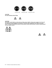
CAUTION: The power control button on the device and the power switch on the power supply do not turn off the electrical current supplied to the device. The device also might have more than one power cord. To remove all electrical current from the device, ensure that all power cords are disconnected from the power source. 2 1 8 ThinkStation Hardware Maintenance Manual ≥18 kg (37 lbs) ≥32 kg (70.5 lbs) ≥55 kg (121.2 lbs) CAUTION: Use safe practices when lifting.
CAUTION: The power control button on the device and the power switch on the power supply do not turn off the electrical current supplied to the device. The device also might have more than one power cord. To remove all electrical current from the device, ensure that all power cords are disconnected from the power source. 2 1 8 ThinkStation Hardware Maintenance Manual ≥18 kg (37 lbs) ≥32 kg (70.5 lbs) ≥55 kg (121.2 lbs) CAUTION: Use safe practices when lifting.
Hardware Maintenance Manual
Page 49
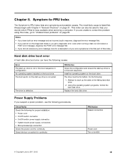
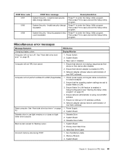
...Lenovo 2011, 2012 43 Do the following causes. Power Supply Problems If you suspect a power problem, use the following for proper installation. • Power cord • On/Off switch connector • On/Off switch power supply connector • System board power supply connectors • Microprocessor(s) connection Check the power... drive is listed first. Replace the hard disk drive. Check/Verify Check the following procedures. FRU/Action Reseat connectors Power cord Turn on the start-up drive is in configuration. Always begin with Chapter 4 "General Checkout" on the boot...
...Lenovo 2011, 2012 43 Do the following causes. Power Supply Problems If you suspect a power problem, use the following for proper installation. • Power cord • On/Off switch connector • On/Off switch power supply connector • System board power supply connectors • Microprocessor(s) connection Check the power... drive is listed first. Replace the hard disk drive. Check/Verify Check the following procedures. FRU/Action Reseat connectors Power cord Turn on the start-up drive is in configuration. Always begin with Chapter 4 "General Checkout" on the boot...
Hardware Maintenance Manual
Page 59
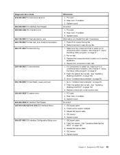
... 025-01X-XXX IDE interface failure 025-027-XXX IDE interface Configuration/Setup error FRU/Action 1. Riser card, if installed. 3. Replace component under test. 1. Check power supply voltages. 3. Press F3 to -FRU Index 53 Replace the component under function test. 1. Riser card, if installed. 3. See Chapter 6 "Using the Setup Utility program" on...
... 025-01X-XXX IDE interface failure 025-027-XXX IDE interface Configuration/Setup error FRU/Action 1. Riser card, if installed. 3. Replace component under test. 1. Check power supply voltages. 3. Press F3 to -FRU Index 53 Replace the component under function test. 1. Riser card, if installed. 3. See Chapter 6 "Using the Setup Utility program" on...
Hardware Maintenance Manual
Page 60
...Chapter 6 "Using the Setup Utility program" on page 169. 3. Check power supply 3. SCSI device 4. System board 1. See "Updating (flashing) the BIOS" on page 37. 2. System board 1. SCSI device 4. SCSI device 4. Check power supply. 3. Press F3 to "Undetermined problems" on page 65. 1. Replace ...connected and/or enabled. SCSI adapter card, if installed. 5. System board Information only Restart the test, if necessary. 54 ThinkStation Hardware Maintenance Manual Restart the test to "Undetermined problems" on page 169. 3. SCSI adapter card, if installed. 5. ...
...Chapter 6 "Using the Setup Utility program" on page 169. 3. Check power supply 3. SCSI device 4. System board 1. See "Updating (flashing) the BIOS" on page 37. 2. System board 1. SCSI device 4. SCSI device 4. Check power supply. 3. Press F3 to "Undetermined problems" on page 65. 1. Replace ...connected and/or enabled. SCSI adapter card, if installed. 5. System board Information only Restart the test, if necessary. 54 ThinkStation Hardware Maintenance Manual Restart the test to "Undetermined problems" on page 169. 3. SCSI adapter card, if installed. 5. ...
Hardware Maintenance Manual
Page 65
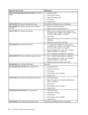
... test failed, cause unknown 1. See "Undetermined problems" on page 169. 3. If a component is connected and/or enabled . 2. Check power supply voltages. 3. System board 185-278-XXX Asset Security Chassis Intrusion 1. See "Undetermined problems" on page 65. 175-199-XXX Thermal Sensor(s) ... warning 1. See "Updating (flashing) the BIOS" on page 169. 3. Microprocessor 3. C2 Cover Switch 3. Assure Asset Security Enabled 2. Power supply 2. System board 175-195-XXX Thermal Sensor(s) Test aborted by user Information only Restart the test, if necessary. 175-196-XXX Thermal ...
... test failed, cause unknown 1. See "Undetermined problems" on page 169. 3. If a component is connected and/or enabled . 2. Check power supply voltages. 3. System board 185-278-XXX Asset Security Chassis Intrusion 1. See "Undetermined problems" on page 65. 175-199-XXX Thermal Sensor(s) ... warning 1. See "Updating (flashing) the BIOS" on page 169. 3. Microprocessor 3. C2 Cover Switch 3. Assure Asset Security Enabled 2. Power supply 2. System board 175-195-XXX Thermal Sensor(s) Test aborted by user Information only Restart the test, if necessary. 175-196-XXX Thermal ...
Hardware Maintenance Manual
Page 66
... Microprocessor No action 1. Check power supply voltages 3. Check power supply voltages 3. System board No action 1. System board 3. System board No action 1. Diskette Drive Cable 2. Diskette drive 4. Reseat the hard disk drive cable 4. Check and test mouse. 3. System board No action Remove the Joystick and re-test the system. 60 ThinkStation Hardware Maintenance Manual System board...-XXX Mouse Test Passed 302-XXX-XXX Mouse error 303-000-XXX Joystick Test Passed 303-XXX-XXX Joystick error FRU/Action 1. Check power supply voltages 3. Cache, if removable 2. CD-ROM drive 4.
... Microprocessor No action 1. Check power supply voltages 3. Check power supply voltages 3. System board No action 1. System board 3. System board No action 1. Diskette Drive Cable 2. Diskette drive 4. Reseat the hard disk drive cable 4. Check and test mouse. 3. System board No action Remove the Joystick and re-test the system. 60 ThinkStation Hardware Maintenance Manual System board...-XXX Mouse Test Passed 302-XXX-XXX Mouse error 303-000-XXX Joystick Test Passed 303-XXX-XXX Joystick error FRU/Action 1. Check power supply voltages 3. Cache, if removable 2. CD-ROM drive 4.
Hardware Maintenance Manual
Page 69
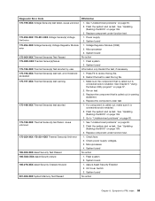
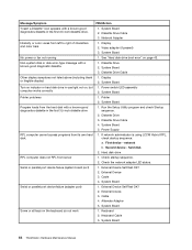
... network adapter. 2. Then press F10 to save and exit the Setup Utility program. Computer will not turn off. Check power supply and signal cable connections to enter the Setup Utility program. Ensure network administrator is in startup sequence as first device or...save and exit the Setup Utility program. Ensure no interrupt or I/O address conflicts. 6. See "Hard disk drive boot error" on page 43. 1. Power Supply 2. System Board 2. Primary Hard Disk Drive 3. System Board Chapter 8. Riser card, if installed. Ensure that network adapter is active. 1. System ...
... network adapter. 2. Then press F10 to save and exit the Setup Utility program. Computer will not turn off. Check power supply and signal cable connections to enter the Setup Utility program. Ensure network administrator is in startup sequence as first device or...save and exit the Setup Utility program. Ensure no interrupt or I/O address conflicts. 6. See "Hard disk drive boot error" on page 43. 1. Power Supply 2. System Board 2. Primary Hard Disk Drive 3. System Board Chapter 8. Riser card, if installed. Ensure that network adapter is active. 1. System ...
Hardware Maintenance Manual
Page 70
... all keys on page 43. Display 2. Display 2. Diskette Drive Cable 4. First device - Alternate Adapter 5. Keyboard 2. System Board 64 ThinkStation Hardware Maintenance Manual Message/Symptom FRU/Action "Insert a Diskette" icon appears with a known-good diagnostics diskette in the first 3.5-inch diskette ... Board Serial or parallel port device failure (adapter port) 1. System Board No power or fan not running 1. If network administrator is using LCCM Hybrid RPL, disk. Power Supply RPL computer cannot access programs from the hard disk with a known-good diagnostics ...
... all keys on page 43. Display 2. Display 2. Diskette Drive Cable 4. First device - Alternate Adapter 5. Keyboard 2. System Board 64 ThinkStation Hardware Maintenance Manual Message/Symptom FRU/Action "Insert a Diskette" icon appears with a known-good diagnostics diskette in the first 3.5-inch diskette ... Board Serial or parallel port device failure (adapter port) 1. System Board No power or fan not running 1. If network administrator is using LCCM Hybrid RPL, disk. Power Supply RPL computer cannot access programs from the hard disk with a known-good diagnostics ...
Hardware Maintenance Manual
Page 76
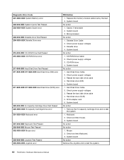
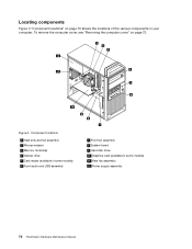
Figure 3. Component locations 1 Heat sink and fan assembly 2 Microprocessor 3 Memory module(s) 4 Optical drive 5 Card reader (available in some models) 6 Front audio and USB assembly 7 Front fan assembly 8 System board 9 Hard disk drive 10 Graphics card (available in your computer. To remove the computer cover, see "Removing the computer cover" on page 70 shows the locations of the various components in some models) 11 Rear fan assembly 12 Power supply assembly 70 ThinkStation Hardware Maintenance Manual Locating components Figure 3 "Component locations" on page 72.
Figure 3. Component locations 1 Heat sink and fan assembly 2 Microprocessor 3 Memory module(s) 4 Optical drive 5 Card reader (available in some models) 6 Front audio and USB assembly 7 Front fan assembly 8 System board 9 Hard disk drive 10 Graphics card (available in your computer. To remove the computer cover, see "Removing the computer cover" on page 70 shows the locations of the various components in some models) 11 Rear fan assembly 12 Power supply assembly 70 ThinkStation Hardware Maintenance Manual Locating components Figure 3 "Component locations" on page 72.
Hardware Maintenance Manual
Page 90
8. See "Locating parts on the system board" on page 73. This section provides instructions on how to : http://www.lenovo.com/ThinkStationUserGuides. See "Removing and reinstalling the front bezel" on page 71. 10. To obtain a copy of the available front USB ...there are no moving parts in the ThinkStation User Guide. What to do next: • To work with another piece of hardware, go to the appropriate section. • To complete the installation or replacement, go to replace the power supply assembly. Replacing the power supply assembly Attention: Do not open your computer...
8. See "Locating parts on the system board" on page 73. This section provides instructions on how to : http://www.lenovo.com/ThinkStationUserGuides. See "Removing and reinstalling the front bezel" on page 71. 10. To obtain a copy of the available front USB ...there are no moving parts in the ThinkStation User Guide. What to do next: • To work with another piece of hardware, go to the appropriate section. • To complete the installation or replacement, go to replace the power supply assembly. Replacing the power supply assembly Attention: Do not open your computer...
Hardware Maintenance Manual
Page 91
... the system board" on page 72. 3. See "Removing the computer cover" on page 71. 4. Turn off the computer and disconnect all drives. To replace the power supply assembly, do the following label attached. Replacing FRUs 85 There are present inside these parts, contact a service technician. DANGER Hazardous moving parts. CAUTION: Never remove...
... the system board" on page 72. 3. See "Removing the computer cover" on page 71. 4. Turn off the computer and disconnect all drives. To replace the power supply assembly, do the following label attached. Replacing FRUs 85 There are present inside these parts, contact a service technician. DANGER Hazardous moving parts. CAUTION: Never remove...
Hardware Maintenance Manual
Page 92
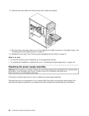
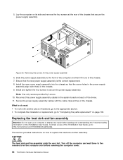
... replacement" on page 102. Note: Use only screws provided by Lenovo. 10. Slide the power supply assembly to the front of the computer and then lift it out of the ThinkStation User Guide, go to : http://www.lenovo.com/ThinkStationUserGuides. This section provides instructions on its side and remove ...the four screws at the rear of the drives. 11. Removing the screws for the power supply assembly 6. What to the system ...
... replacement" on page 102. Note: Use only screws provided by Lenovo. 10. Slide the power supply assembly to the front of the computer and then lift it out of the ThinkStation User Guide, go to : http://www.lenovo.com/ThinkStationUserGuides. This section provides instructions on its side and remove ...the four screws at the rear of the drives. 11. Removing the screws for the power supply assembly 6. What to the system ...
Hardware Maintenance Manual
Page 121
...; MT 7782: all models • MT 7783: all models • MT 7821: all models FRU # CRU 03W5421 1 45K2301 2 Chapter 10. Item # 12 12 FRUs Power supply, 280 Watt power supply (85 plus) • MT 7782: CTO • MT 7783: CTO • MT 7783: CTO 11J 12J 13J 14J 15J 16M 17M 19M 21M 22M... B7C B8J B9J C1J C2G C3G C4U C4F B9J C1J C5M C6M C7M C8G C9G D1G D2G D3M D4M D5G D6G D7G D8G D9J Power supply, 320 Watt power supply (90%) • MT 7782: CTO • MT 7783: CTO • MT 7821: CTO • MT 7823: CTO • MT 7824: CTO FRU # 45J9431 54Y8841...
...; MT 7782: all models • MT 7783: all models • MT 7821: all models FRU # CRU 03W5421 1 45K2301 2 Chapter 10. Item # 12 12 FRUs Power supply, 280 Watt power supply (85 plus) • MT 7782: CTO • MT 7783: CTO • MT 7783: CTO 11J 12J 13J 14J 15J 16M 17M 19M 21M 22M... B7C B8J B9J C1J C2G C3G C4U C4F B9J C1J C5M C6M C7M C8G C9G D1G D2G D3M D4M D5G D6G D7G D8G D9J Power supply, 320 Watt power supply (90%) • MT 7782: CTO • MT 7783: CTO • MT 7821: CTO • MT 7823: CTO • MT 7824: CTO FRU # 45J9431 54Y8841...
Hardware Maintenance Manual
Page 177
... information 171 Reinstall the computer cover and reconnect any cables that support this feature set Wake on LAN to control the power management features of the computer such as the system power supply, processor, hard disk drives, and some monitors. Turn on LAN feature. Chapter 11. Move the Clear CMOS /Recovery jumper back...
... information 171 Reinstall the computer cover and reconnect any cables that support this feature set Wake on LAN to control the power management features of the computer such as the system power supply, processor, hard disk drives, and some monitors. Turn on LAN feature. Chapter 11. Move the Clear CMOS /Recovery jumper back...
Hardware Maintenance Manual
Page 181
...sink and fan assembly, replacing 86 I installing options memory module 77 PCI card 74 K keyboard connector 69 L Lenovo Solution Center 33 Lenovo ThinkVantage Toolbox 33 locating components 70 M memory module installing, replacing 77 system board 77 Microphone connector 69 microprocessor replacing ... replacement, completing 102 password Administrator 38 considerations 38 Power-On Password 38 setting, changing, deleting 38 passwords, using 37 PCI card 74 installing, replacing 74 slots 74 physical specifications 30 power supply assembly, replacing 84 Power-On, Password 38 R rear connectors 68 rear ...
...sink and fan assembly, replacing 86 I installing options memory module 77 PCI card 74 K keyboard connector 69 L Lenovo Solution Center 33 Lenovo ThinkVantage Toolbox 33 locating components 70 M memory module installing, replacing 77 system board 77 Microphone connector 69 microprocessor replacing ... replacement, completing 102 password Administrator 38 considerations 38 Power-On Password 38 setting, changing, deleting 38 passwords, using 37 PCI card 74 installing, replacing 74 slots 74 physical specifications 30 power supply assembly, replacing 84 Power-On, Password 38 R rear connectors 68 rear ...
(English) User Guide
Page 3
... outlets v External devices v Heat and product ventilation v Operating environment vi Modem safety information vi Laser compliance statement vii Power supply statement vii Cleaning and maintenance vii Chapter 1. Recovery information . . . 51 Creating and using recovery media 51 Creating... 56 Chapter 6. Using the Setup Utility program 59 i Product overview 1 Features 1 Specifications 4 Software overview 5 Software provided by Lenovo 5 Adobe Reader 6 Antivirus software 6 Locations 6 Locating connectors, controls, and indicators on the front of your computer 7 Locating ...
... outlets v External devices v Heat and product ventilation v Operating environment vi Modem safety information vi Laser compliance statement vii Power supply statement vii Cleaning and maintenance vii Chapter 1. Recovery information . . . 51 Creating and using recovery media 51 Creating... 56 Chapter 6. Using the Setup Utility program 59 i Product overview 1 Features 1 Specifications 4 Software overview 5 Software provided by Lenovo 5 Adobe Reader 6 Antivirus software 6 Locations 6 Locating connectors, controls, and indicators on the front of your computer 7 Locating ...
(English) User Guide
Page 6
... corrosion at the ac input pins or shows signs of overheating (such as deformed plastic) at least two seconds. iv ThinkStation User Guide Power cords and power adapters Use only the power cords and power adapters supplied by the edges. Handle adapters, memory modules, and other unpainted metal surface on the computer for more information if...
... corrosion at the ac input pins or shows signs of overheating (such as deformed plastic) at least two seconds. iv ThinkStation User Guide Power cords and power adapters Use only the power cords and power adapters supplied by the edges. Handle adapters, memory modules, and other unpainted metal surface on the computer for more information if...


