(English) Power Manager Deployment Guide
Page 11
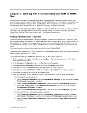
..., and any type of policy settings: General Setting, Power Plan (Scheme) Deployments, Global Power Settings, Battery Maintenance, and Power Agenda Deployments. b. c. The mechanism is present. Click Add/Remove Templates, and the Add/Remove Templates window opens. 4. A new item named Lenovo ThinkVantage Components is known as Group Policy and Administrative Template (ADM or ADMX) files...
..., and any type of policy settings: General Setting, Power Plan (Scheme) Deployments, Global Power Settings, Battery Maintenance, and Power Agenda Deployments. b. c. The mechanism is present. Click Add/Remove Templates, and the Add/Remove Templates window opens. 4. A new item named Lenovo ThinkVantage Components is known as Group Policy and Administrative Template (ADM or ADMX) files...

Hardware Maintenance Manual
Page 3
... System supporting the Lenovo ThinkVantage Toolbox program and the PC-Doctor for wireless WAN . . 72 1130 mSATA solid state drive 73 1140 Bluetooth daughter card 75 1150 Media Card Reader slot board assembly . . 75 i Removing and replacing a FRU 57 Before servicing ThinkPad Edge E420s and S420 57 ...1010 ExpressCard blank bezel and Media Card blank bezel 58 1020 Hard disk drive or solid state drive assembly 60 1030 Keyboard 61 1040 Top case assembly 63 1050 Backup battery 65 1060 Speaker assembly...
... System supporting the Lenovo ThinkVantage Toolbox program and the PC-Doctor for wireless WAN . . 72 1130 mSATA solid state drive 73 1140 Bluetooth daughter card 75 1150 Media Card Reader slot board assembly . . 75 i Removing and replacing a FRU 57 Before servicing ThinkPad Edge E420s and S420 57 ...1010 ExpressCard blank bezel and Media Card blank bezel 58 1020 Hard disk drive or solid state drive assembly 60 1030 Keyboard 61 1040 Top case assembly 63 1050 Backup battery 65 1060 Speaker assembly...

Hardware Maintenance Manual
Page 9
... should use the following checklist at the same charge. Check for cracked or bulging batteries. 5. Use product-specific ESD procedures when they present: • Electrical hazards, ...fasteners (screws or rivets) have not been removed or tampered with the power off, and the power cord disconnected. If any non-ThinkPad alterations. 7. Remove the cover. 6. Use good judgment as metal... cables. 9. Notes: 1. Check the power cord for damage (loose, broken, or sharp edges). 2. Protect against ESD damage by this inspection guide is a difference in good condition. As...
... should use the following checklist at the same charge. Check for cracked or bulging batteries. 5. Use product-specific ESD procedures when they present: • Electrical hazards, ...fasteners (screws or rivets) have not been removed or tampered with the power off, and the power cord disconnected. If any non-ThinkPad alterations. 7. Remove the cover. 6. Use good judgment as metal... cables. 9. Notes: 1. Check the power cord for damage (loose, broken, or sharp edges). 2. Protect against ESD damage by this inspection guide is a difference in good condition. As...
Hardware Maintenance Manual
Page 41
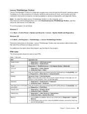
... 1. If two DIMMs are installed, remove one , and run this test. Chapter 3. Note: To install the latest Lenovo ThinkVantage Toolbox on the computer, go to http://web.lenovothinkvantagetoolbox.com/ click Download Lenovo ThinkVantage Toolbox, and then follow the ...Windows XP: Click Start ➙ All Programs ➙ ThinkVantage ➙ Lenovo ThinkVantage Toolbox. FRU tests FRU Applicable test System board 1. Diagnostics ➙ Systemboard Power Diagnostics ➙ ThinkPad Devices ➙ AC Adapter, Battery 1 (Battery2) LCD unit 1. In this test again. Then, run ...
... 1. If two DIMMs are installed, remove one , and run this test. Chapter 3. Note: To install the latest Lenovo ThinkVantage Toolbox on the computer, go to http://web.lenovothinkvantagetoolbox.com/ click Download Lenovo ThinkVantage Toolbox, and then follow the ...Windows XP: Click Start ➙ All Programs ➙ ThinkVantage ➙ Lenovo ThinkVantage Toolbox. FRU tests FRU Applicable test System board 1. Diagnostics ➙ Systemboard Power Diagnostics ➙ ThinkPad Devices ➙ AC Adapter, Battery 1 (Battery2) LCD unit 1. In this test again. Then, run ...

Hardware Maintenance Manual
Page 44
...When the Boot Menu window opens, release the F12 key. 4. Turn on page 45 for error code descriptions and troubleshooting hints. 2. When the ThinkPad logo is displayed, repeatedly press and release the F12 key. If you suspect a power problem, see the appropriate one of the ac power ... instructions on page 39 To check the ac power adapter, do the following figure: 38 Hardware Maintenance Manual Remove the battery pack. 3. Disconnect the ac power adapter and install the charged battery pack. 7. Unplug the ac power adapter cable from the computer. 2. If an error code is supplied when...
...When the Boot Menu window opens, release the F12 key. 4. Turn on page 45 for error code descriptions and troubleshooting hints. 2. When the ThinkPad logo is displayed, repeatedly press and release the F12 key. If you suspect a power problem, see the appropriate one of the ac power ... instructions on page 39 To check the ac power adapter, do the following figure: 38 Hardware Maintenance Manual Remove the battery pack. 3. Disconnect the ac power adapter and install the charged battery pack. 7. Unplug the ac power adapter cable from the computer. 2. If an error code is supplied when...

Hardware Maintenance Manual
Page 45
...the charge indicator or icon still does not turn on , remove the battery pack and let it return to "FRU tests" on , replace the system board. Checking the battery pack Battery charging does not start until the Power Manager Battery Gauge shows that has less than 96% of the total ...power remains; under this condition the battery pack can charge to the next section. Remove the backup battery (see "1090 Battery pack" on page 65). 5. General checkout 39 This protects the battery pack from being overcharged or from the ac power adapter does not always...
...the charge indicator or icon still does not turn on , remove the battery pack and let it return to "FRU tests" on , replace the system board. Checking the battery pack Battery charging does not start until the Power Manager Battery Gauge shows that has less than 96% of the total ...power remains; under this condition the battery pack can charge to the next section. Remove the backup battery (see "1090 Battery pack" on page 65). 5. General checkout 39 This protects the battery pack from being overcharged or from the ac power adapter does not always...

Hardware Maintenance Manual
Page 49
...Lenovo nor Lenovo authorized service technicians provide any services to reset either the user or the master HDP, or to reset the password. For how to the ThinkPad Setup and change the system configuration. The POP has been removed. 5. Type in order to get access to remove the backup battery, see "1090 Battery... pack" on the computer. How to remove the hard-disk password Attention: If User...
...Lenovo nor Lenovo authorized service technicians provide any services to reset either the user or the master HDP, or to reset the password. For how to the ThinkPad Setup and change the system configuration. The POP has been removed. 5. Type in order to get access to remove the backup battery, see "1090 Battery... pack" on the computer. How to remove the hard-disk password Attention: If User...

Hardware Maintenance Manual
Page 50
... on the computer. 2. Wait a few seconds before taking any key. Turn on the power switch. Both user HDP and master HDP will have been removed. Select Power off . • The CPU stops. A pop-up , immediately press F1 to move down the menu. 4. Screen blank mode To put... is signaled by a serial device or a PC Card device. • The time set the low-battery alarm, the charge indicator notifies you do any input immediately after it enters sleep (standby) mode. When the ThinkPad logo comes up window opens. 6. Select Password. 5. Select Hard-disk x password, where x is powered...
... on the computer. 2. Wait a few seconds before taking any key. Turn on the power switch. Both user HDP and master HDP will have been removed. Select Power off . • The CPU stops. A pop-up , immediately press F1 to move down the menu. 4. Screen blank mode To put... is signaled by a serial device or a PC Card device. • The time set the low-battery alarm, the charge indicator notifies you do any input immediately after it enters sleep (standby) mode. When the ThinkPad logo comes up window opens. 6. Select Password. 5. Select Hard-disk x password, where x is powered...
Hardware Maintenance Manual
Page 52
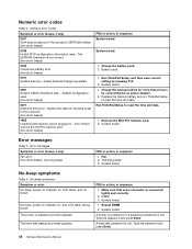
...CMOS checksum bad- System board. Charge the battery pack. 2. Fan. 2. A power-on password prompt appears. Error messages Table 3. Type the password and press Enter. 46 Hardware Maintenance Manual System board. 1. Remove the Mini PCI network card. 2. System ...board. System board. 1. System board. Default configuration used. (two short beeps) 0271 Date and time error-Neither the date nor the time is set in sequence System board. The hard-disk password prompt appears. Replace the backup battery and run ThinkPad...
...CMOS checksum bad- System board. Charge the battery pack. 2. Fan. 2. A power-on password prompt appears. Error messages Table 3. Type the password and press Enter. 46 Hardware Maintenance Manual System board. 1. Remove the Mini PCI network card. 2. System ...board. System board. 1. System board. Default configuration used. (two short beeps) 0271 Date and time error-Neither the date nor the time is set in sequence System board. The hard-disk password prompt appears. Replace the backup battery and run ThinkPad...
Hardware Maintenance Manual
Page 54
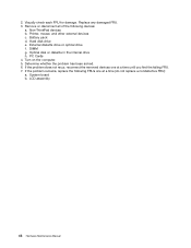
... damaged FRU. 3. Non-ThinkPad devices b. PC Cards 4. Determine whether the problem has been solved. 6. Remove or disconnect all of the following FRUs one at a time (do not replace a nondefective FRU): a. Battery pack d. LCD assembly 48 Hardware Maintenance Manual Hard disk drive e. If the problem does not recur, reconnect the removed devices one at a time...
... damaged FRU. 3. Non-ThinkPad devices b. PC Cards 4. Determine whether the problem has been solved. 6. Remove or disconnect all of the following FRUs one at a time (do not replace a nondefective FRU): a. Battery pack d. LCD assembly 48 Hardware Maintenance Manual Hard disk drive e. If the problem does not recur, reconnect the removed devices one at a time...

Hardware Maintenance Manual
Page 63
...and other small parts are in which they are loose inside the computer. Before servicing ThinkPad Edge E420s and S420 Some models of Self-service CRUs is replaced by , electrostatic discharge. Removing and replacing a FRU External CRU statement to return the defective part that have been ...SIM card that all power cords from Lenovo at http://www.lenovo.com/CRUs. Before replacing any interconnecting cables. Begin by removing any FRU, turn on the computer until you . Any such FRUs are available from electrical outlets, remove the battery pack, and then disconnect any FRU, ...
...and other small parts are in which they are loose inside the computer. Before servicing ThinkPad Edge E420s and S420 Some models of Self-service CRUs is replaced by , electrostatic discharge. Removing and replacing a FRU External CRU statement to return the defective part that have been ...SIM card that all power cords from Lenovo at http://www.lenovo.com/CRUs. Before replacing any interconnecting cables. Begin by removing any FRU, turn on the computer until you . Any such FRUs are available from electrical outlets, remove the battery pack, and then disconnect any FRU, ...
Hardware Maintenance Manual
Page 71
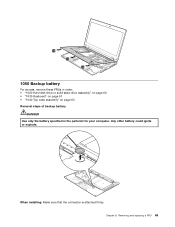
13 13 13 1050 Backup battery For access, remove these FRUs in order: • "1020 Hard disk drive or solid state drive assembly" on page 60 • "1030 Keyboard" on page 61 • "1040 Top case assembly" on page 63 Removal steps of backup battery DANGER Use only the battery specified in the parts list for your computer. When installing: Make sure that the connector is attached firmly. Removing and replacing a FRU 65 Chapter 8. Any other battery could ignite or explode.
13 13 13 1050 Backup battery For access, remove these FRUs in order: • "1020 Hard disk drive or solid state drive assembly" on page 60 • "1030 Keyboard" on page 61 • "1040 Top case assembly" on page 63 Removal steps of backup battery DANGER Use only the battery specified in the parts list for your computer. When installing: Make sure that the connector is attached firmly. Removing and replacing a FRU 65 Chapter 8. Any other battery could ignite or explode.

Hardware Maintenance Manual
Page 72
...drive assembly" on page 60 • "1030 Keyboard" on page 61 • "1040 Top case assembly" on page 63 • "1090 Battery pack" on page 68 Removal steps of speaker assembly 1 1 1 1 2 2 When installing: Make sure that the connector is attached firmly. 1070 Fingerprint reader 1070 Fingerprint ...reader For access, remove these FRUs in order: • "1020 Hard disk drive or solid state drive assembly" on page 60 • "1030 Keyboard" on page ...
...drive assembly" on page 60 • "1030 Keyboard" on page 61 • "1040 Top case assembly" on page 63 • "1090 Battery pack" on page 68 Removal steps of speaker assembly 1 1 1 1 2 2 When installing: Make sure that the connector is attached firmly. 1070 Fingerprint reader 1070 Fingerprint ...reader For access, remove these FRUs in order: • "1020 Hard disk drive or solid state drive assembly" on page 60 • "1030 Keyboard" on page ...

Hardware Maintenance Manual
Page 74
.... • If Lenovo ThinkVantage Toolbox is not installed in the computer, the customer should not be replaced unless this diagnostic shows that the battery is defective. • The only exception to reset the computer. Any other battery could ignite or explode. Then detach the battery connector 2 . 68 Hardware Maintenance Manual Remove the battery 1 . A battery pack FRU should...
.... • If Lenovo ThinkVantage Toolbox is not installed in the computer, the customer should not be replaced unless this diagnostic shows that the battery is defective. • The only exception to reset the computer. Any other battery could ignite or explode. Then detach the battery connector 2 . 68 Hardware Maintenance Manual Remove the battery 1 . A battery pack FRU should...
Hardware Maintenance Manual
Page 75
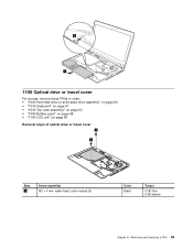
2 1 1100 Optical drive or travel cover For access, remove these FRUs in order: • "1020 Hard disk drive or solid state drive assembly" on page 60 • "1030 Keyboard" on page 61 • "1040 Top case assembly" on page 63 • "1090 Battery pack" on page 68 • "1180 LCD unit" on page 80 Removal steps of optical drive or travel cover 1 1 Step 1 Screw (quantity) M2 × 4 mm, wafer-head, nylon-coated (2) Color Black Torque 0.181 Nm (1.85 kgfcm) Chapter 8. Removing and replacing a FRU 69
2 1 1100 Optical drive or travel cover For access, remove these FRUs in order: • "1020 Hard disk drive or solid state drive assembly" on page 60 • "1030 Keyboard" on page 61 • "1040 Top case assembly" on page 63 • "1090 Battery pack" on page 68 • "1180 LCD unit" on page 80 Removal steps of optical drive or travel cover 1 1 Step 1 Screw (quantity) M2 × 4 mm, wafer-head, nylon-coated (2) Color Black Torque 0.181 Nm (1.85 kgfcm) Chapter 8. Removing and replacing a FRU 69

Hardware Maintenance Manual
Page 76
Make sure that it snaps into the socket. Removal steps of DIMM (bottom slot) For access, remove these FRUs in the slot and does not move easily. 2 1110 DIMM Removal steps of DIMM (upper slot) For access, remove "1030 Keyboard" on page 82 70 Hardware Maintenance Manual Press the DIMM in firmly, and pivot it..." on page 71 • "1130 PCI Express Mini Card for wireless WAN" on page 72 • "1040 Top case assembly" on page 63 • "1090 Battery pack" on page 68 • "1160 System board assembly and fan assembly" on page 76 • "1180 LCD unit" on page 80 • "2010 LCD...
Make sure that it snaps into the socket. Removal steps of DIMM (bottom slot) For access, remove these FRUs in the slot and does not move easily. 2 1110 DIMM Removal steps of DIMM (upper slot) For access, remove "1030 Keyboard" on page 82 70 Hardware Maintenance Manual Press the DIMM in firmly, and pivot it..." on page 71 • "1130 PCI Express Mini Card for wireless WAN" on page 72 • "1040 Top case assembly" on page 63 • "1090 Battery pack" on page 68 • "1160 System board assembly and fan assembly" on page 76 • "1180 LCD unit" on page 80 • "2010 LCD...
Hardware Maintenance Manual
Page 81
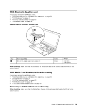
... solid state drive assembly" on page 60 • "1030 Keyboard" on page 61 • "1040 Top case assembly" on page 63 • "1090 Battery pack" on page 68 Removal steps of bluetooth daughter card 1 2 Step 1 Screw (quantity) M2 × 4 mm, wafer-head, nylon-coated (1) Color Black Torque 0.181 Nm (1.85 ... • "1030 Keyboard" on page 61 • "1040 Top case assembly" on page 63 • "1090 Battery pack" on page 68 • "1100 Optical drive or travel cover" on page 69 Removal steps of Media Card Reader slot board assembly When installing: Make sure that the Media Card Reader slot...
... solid state drive assembly" on page 60 • "1030 Keyboard" on page 61 • "1040 Top case assembly" on page 63 • "1090 Battery pack" on page 68 Removal steps of bluetooth daughter card 1 2 Step 1 Screw (quantity) M2 × 4 mm, wafer-head, nylon-coated (1) Color Black Torque 0.181 Nm (1.85 ... • "1030 Keyboard" on page 61 • "1040 Top case assembly" on page 63 • "1090 Battery pack" on page 68 • "1100 Optical drive or travel cover" on page 69 Removal steps of Media Card Reader slot board assembly When installing: Make sure that the Media Card Reader slot...
Hardware Maintenance Manual
Page 83
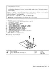
...LCD unit" on page 80 • "2010 LCD bezel assembly" on page 82 Removal steps of system board 1 1 1 Step 2 Screw (quantity) M2 × 4 mm,...-coated (3) Color Black Torque 0.181 Nm (1.85 kgfcm) Chapter 8. For access, remove these FRUs in the process, be sure not to drop or stack the system board... that the HDD Active Protection System still functions. The procedure is running. Removing and replacing a FRU 77 • Avoid rough handling of any kind....• "1040 Top case assembly" on page 63 • "1090 Battery pack" on page 68 • "1120 PCI Express Mini Card for ...
...LCD unit" on page 80 • "2010 LCD bezel assembly" on page 82 Removal steps of system board 1 1 1 Step 2 Screw (quantity) M2 × 4 mm,...-coated (3) Color Black Torque 0.181 Nm (1.85 kgfcm) Chapter 8. For access, remove these FRUs in the process, be sure not to drop or stack the system board... that the HDD Active Protection System still functions. The procedure is running. Removing and replacing a FRU 77 • Avoid rough handling of any kind....• "1040 Top case assembly" on page 63 • "1090 Battery pack" on page 68 • "1120 PCI Express Mini Card for ...

Hardware Maintenance Manual
Page 84
Removal steps of fan assembly 1 2 2 Step 1 Screw (quantity) M2 × 4 mm, wafer-head, nylon-coated (2) Color Black 1170 DC-in sub card For access, remove these FRUs in order: • "1020 Hard disk drive or solid state drive assembly" on page 60 • "1030 Keyboard" on page 61 • "1040 Top case assembly" on page 63 • "1090 Battery pack" on page 68 • "1160 System board assembly and fan assembly" on page 76 Torque 0.181 Nm (1.85 kgfcm) 78 Hardware Maintenance Manual 3 When installing: Make sure that the connectors are attached firmly.
Removal steps of fan assembly 1 2 2 Step 1 Screw (quantity) M2 × 4 mm, wafer-head, nylon-coated (2) Color Black 1170 DC-in sub card For access, remove these FRUs in order: • "1020 Hard disk drive or solid state drive assembly" on page 60 • "1030 Keyboard" on page 61 • "1040 Top case assembly" on page 63 • "1090 Battery pack" on page 68 • "1160 System board assembly and fan assembly" on page 76 Torque 0.181 Nm (1.85 kgfcm) 78 Hardware Maintenance Manual 3 When installing: Make sure that the connectors are attached firmly.

Hardware Maintenance Manual
Page 86
1180 LCD unit For access, remove these FRUs in order: • "1020 Hard disk drive or solid state drive assembly" on page 60 • "1030 Keyboard" on page 61 • "1040 Top case assembly" on page 63 • "1090 Battery pack" on page 68 Removal steps of LCD unit 1 Step 1 Screw (quantity) M2 × 4 mm, wafer-head, nylon-coated (2) 1 Color Black Torque 0.181 Nm (1.85 kgfcm) 2 2 Step 2 Screw (quantity) M2 × 4 mm, wafer-head, nylon-coated (2) Detach cables from the cable guides. Color Black Torque 0.181 Nm (1.85 kgfcm) 80 Hardware Maintenance Manual
1180 LCD unit For access, remove these FRUs in order: • "1020 Hard disk drive or solid state drive assembly" on page 60 • "1030 Keyboard" on page 61 • "1040 Top case assembly" on page 63 • "1090 Battery pack" on page 68 Removal steps of LCD unit 1 Step 1 Screw (quantity) M2 × 4 mm, wafer-head, nylon-coated (2) 1 Color Black Torque 0.181 Nm (1.85 kgfcm) 2 2 Step 2 Screw (quantity) M2 × 4 mm, wafer-head, nylon-coated (2) Detach cables from the cable guides. Color Black Torque 0.181 Nm (1.85 kgfcm) 80 Hardware Maintenance Manual


