
User Manual
Page 5
... to do first 44 Checkout guide 45 Diagnostics using PC-Doctor for DOS . . . . 45 Lenovo ThinkVantage Toolbox (Lenovo System Toolbox 48 PC-Doctor for Rescue and Recovery . . . . . 48 FRU tests 49 ...Retaining the UUID 82 Reading or writing the ECA information . . . 83 Removing and replacing a FRU . . . . 85 Before servicing ThinkPad T510, T510i, and W510 86 1010 Battery pack 87 1020 Serial Ultrabay Enhanced ...disk drive (HDD) and HDD rubber rails or Solid state drive (SSD) and storage converter 91 1060 Keyboard 93 1070 DIMM (upper slot 97 1080 PCI Express Mini Card for wireless LAN . . . 98...
... to do first 44 Checkout guide 45 Diagnostics using PC-Doctor for DOS . . . . 45 Lenovo ThinkVantage Toolbox (Lenovo System Toolbox 48 PC-Doctor for Rescue and Recovery . . . . . 48 FRU tests 49 ...Retaining the UUID 82 Reading or writing the ECA information . . . 83 Removing and replacing a FRU . . . . 85 Before servicing ThinkPad T510, T510i, and W510 86 1010 Battery pack 87 1020 Serial Ultrabay Enhanced ...disk drive (HDD) and HDD rubber rails or Solid state drive (SSD) and storage converter 91 1060 Keyboard 93 1070 DIMM (upper slot 97 1080 PCI Express Mini Card for wireless LAN . . . 98...

User Manual
Page 102
Removal steps of keyboard (continued) Push down the keyboard a little toward the arrow 2 until the front edge of the keyboard is detached from the keyboard bezel. 2 Lift the keyboard a little in the direction shown by arrow 3 , and then detach the connector 4 . 3 4 94 ThinkPad T510, T510i, and W510 Hardware Maintenance Manual Table 17.
Removal steps of keyboard (continued) Push down the keyboard a little toward the arrow 2 until the front edge of the keyboard is detached from the keyboard bezel. 2 Lift the keyboard a little in the direction shown by arrow 3 , and then detach the connector 4 . 3 4 94 ThinkPad T510, T510i, and W510 Hardware Maintenance Manual Table 17.

User Manual
Page 106
Removal steps of the arrow. Note: Some models might have only two antenna cables in direction of PCI Express Mini Card for wireless LAN For access, remove these FRUs in order: v "1010 Battery pack" on page 87 v "1030 DIMM slot cover" on page 89 v "1060 Keyboard" on page 93 Table 20. 1080 PCI Express Mini Card for wireless LAN In step 1 , unplug the jacks by using the removal tool antenna RF connector (P/N: 08K7159) or pick the connectors with your fingers and gently unplug them in step 1 . 1 1 1 98 ThinkPad T510, T510i, and W510 Hardware Maintenance Manual
Removal steps of the arrow. Note: Some models might have only two antenna cables in direction of PCI Express Mini Card for wireless LAN For access, remove these FRUs in order: v "1010 Battery pack" on page 87 v "1030 DIMM slot cover" on page 89 v "1060 Keyboard" on page 93 Table 20. 1080 PCI Express Mini Card for wireless LAN In step 1 , unplug the jacks by using the removal tool antenna RF connector (P/N: 08K7159) or pick the connectors with your fingers and gently unplug them in step 1 . 1 1 1 98 ThinkPad T510, T510i, and W510 Hardware Maintenance Manual

User Manual
Page 112
Removal steps of ExpressCard blank bezel or ExpressCard (continued) When installing: Make sure that the bezel or the card is attached to the keyboard bezel. 2 2 2 1 1 1 2 12 Step 1 Screw (quantity) M2 × 4 mm, bind-head, nylon-coated (4) Color Black 2 M2 × 14 mm, bind-head, nylon-coated (7) Black Torque 0.181 Nm (1.85 kgfcm) 0.181 Nm (1.85 kgfcm) 104 ThinkPad T510, T510i, and W510 Hardware Maintenance Manual Table 22. Table 23. Removal steps of keyboard bezel assembly Note: The speaker assembly is correctly oriented as shown in this figure.
Removal steps of ExpressCard blank bezel or ExpressCard (continued) When installing: Make sure that the bezel or the card is attached to the keyboard bezel. 2 2 2 1 1 1 2 12 Step 1 Screw (quantity) M2 × 4 mm, bind-head, nylon-coated (4) Color Black 2 M2 × 14 mm, bind-head, nylon-coated (7) Black Torque 0.181 Nm (1.85 kgfcm) 0.181 Nm (1.85 kgfcm) 104 ThinkPad T510, T510i, and W510 Hardware Maintenance Manual Table 22. Table 23. Removal steps of keyboard bezel assembly Note: The speaker assembly is correctly oriented as shown in this figure.
User Manual
Page 114
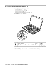
1110 Bluetooth daughter card (BDC-2.1) For access, remove these FRUs in order: v "1010 Battery pack" on page 87 v "1030 DIMM slot cover" on page 89 v "1060 Keyboard" on page 93 v "1100 Keyboard bezel assembly" on page 103 Table 24. Removal steps of BDC-2.1 1 2 Step 1 Screw (quantity) M2 × 3 mm, wafer-head, nylon-coated (1) Color Silver Torque 0.181 Nm (1.85 kgfcm) When installing: Make sure that the connector is attached firmly. 106 ThinkPad T510, T510i, and W510 Hardware Maintenance Manual
1110 Bluetooth daughter card (BDC-2.1) For access, remove these FRUs in order: v "1010 Battery pack" on page 87 v "1030 DIMM slot cover" on page 89 v "1060 Keyboard" on page 93 v "1100 Keyboard bezel assembly" on page 103 Table 24. Removal steps of BDC-2.1 1 2 Step 1 Screw (quantity) M2 × 3 mm, wafer-head, nylon-coated (1) Color Silver Torque 0.181 Nm (1.85 kgfcm) When installing: Make sure that the connector is attached firmly. 106 ThinkPad T510, T510i, and W510 Hardware Maintenance Manual

User Manual
Page 116
1130 Smart Card or Contactless Smart Card or Smart Card dummy spacer For access, remove these FRUs in order: v "1010 Battery pack" on page 87 v "1030 DIMM slot cover" on page 89 v "1060 Keyboard" on page 93 v "1100 Keyboard bezel assembly" on page 103 Table 26. Removal steps of Smart Card 3 3 4 1 2 Step 3 Screw (quantity) M2 × 3 mm, wafer-head, nylon-coated (4) Color Silver Torque 0.181 Nm (1.85 kgfcm) 108 ThinkPad T510, T510i, and W510 Hardware Maintenance Manual
1130 Smart Card or Contactless Smart Card or Smart Card dummy spacer For access, remove these FRUs in order: v "1010 Battery pack" on page 87 v "1030 DIMM slot cover" on page 89 v "1060 Keyboard" on page 93 v "1100 Keyboard bezel assembly" on page 103 Table 26. Removal steps of Smart Card 3 3 4 1 2 Step 3 Screw (quantity) M2 × 3 mm, wafer-head, nylon-coated (4) Color Silver Torque 0.181 Nm (1.85 kgfcm) 108 ThinkPad T510, T510i, and W510 Hardware Maintenance Manual

User Manual
Page 124
...FRUs in the direction shown by arrow 1 to secure the CPU. 116 ThinkPad T510, T510i, and W510 Hardware Maintenance Manual Removal steps of CPU Rotate the head of the screw in the direction shown by arrow a to release the lock; then remove the CPU 2 . 2 1 a When installing: Place the CPU on ...page 113 Attention: CPU is extremely sensitive. When you service the CPU, avoid any kind of the screw in order: v "1010 Battery pack" on page 87 v "1030 DIMM slot cover" on page 89 v "1060 Keyboard" on page 93 v "1100 Keyboard ...
...FRUs in the direction shown by arrow 1 to secure the CPU. 116 ThinkPad T510, T510i, and W510 Hardware Maintenance Manual Removal steps of CPU Rotate the head of the screw in the direction shown by arrow a to release the lock; then remove the CPU 2 . 2 1 a When installing: Place the CPU on ...page 113 Attention: CPU is extremely sensitive. When you service the CPU, avoid any kind of the screw in order: v "1010 Battery pack" on page 87 v "1030 DIMM slot cover" on page 89 v "1060 Keyboard" on page 93 v "1100 Keyboard ...
User Manual
Page 132
... I /O sub card For access, remove these FRUs in order: v "1010 Battery pack" on page 87 v "1020 Serial Ultrabay Enhanced device or travel bezel" ...1080 PCI Express Mini Card for wireless LAN" on page 98 v "1090 PCI Express Mini Card for wireless WAN" on page 101 v "1100 Keyboard bezel assembly" on page 103 v "1110 Bluetooth daughter card (BDC-2.1)" on page 106 v "1120 Backup battery" on page 107 v "1130 ... nylon-coated (3) Color Silver Torque 0.181 Nm (1.85 kgfcm) When installing: Make sure that the connector is attached firmly. 124 ThinkPad T510, T510i, and W510 Hardware Maintenance Manual
... I /O sub card For access, remove these FRUs in order: v "1010 Battery pack" on page 87 v "1020 Serial Ultrabay Enhanced device or travel bezel" ...1080 PCI Express Mini Card for wireless LAN" on page 98 v "1090 PCI Express Mini Card for wireless WAN" on page 101 v "1100 Keyboard bezel assembly" on page 103 v "1110 Bluetooth daughter card (BDC-2.1)" on page 106 v "1120 Backup battery" on page 107 v "1130 ... nylon-coated (3) Color Silver Torque 0.181 Nm (1.85 kgfcm) When installing: Make sure that the connector is attached firmly. 124 ThinkPad T510, T510i, and W510 Hardware Maintenance Manual

User Manual
Page 140
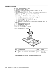
..., and hinges In step 1 , release the antenna cables from the left and right hinges. 1 1 132 ThinkPad T510, T510i, and W510 Hardware Maintenance Manual 2040 LCD cable, camera cable, LCD panel, and hinges For access, remove these FRUs in order: v "1010 Battery pack" on page 87 v "1030 DIMM slot cover" on page...or Solid state drive (SSD) and storage converter" on page 91 v "1060 Keyboard" on page 93 v "1080 PCI Express Mini Card for wireless LAN" on page 98 v "1090 PCI Express Mini Card for wireless WAN" on page 101 v "1100 Keyboard bezel assembly" on page 103 v "1170 LCD unit" on page 117 v...
..., and hinges In step 1 , release the antenna cables from the left and right hinges. 1 1 132 ThinkPad T510, T510i, and W510 Hardware Maintenance Manual 2040 LCD cable, camera cable, LCD panel, and hinges For access, remove these FRUs in order: v "1010 Battery pack" on page 87 v "1030 DIMM slot cover" on page...or Solid state drive (SSD) and storage converter" on page 91 v "1060 Keyboard" on page 93 v "1080 PCI Express Mini Card for wireless LAN" on page 98 v "1090 PCI Express Mini Card for wireless WAN" on page 101 v "1100 Keyboard bezel assembly" on page 103 v "1170 LCD unit" on page 117 v...


