
User Manual
Page 5
... and GAV products 41 General checkout 43 What to do first 44 Checkout guide 45 Diagnostics using PC-Doctor for DOS . . . . 45 Lenovo ThinkVantage Toolbox (Lenovo System Toolbox 48 PC-Doctor for Rescue and Recovery . . . . . 48 FRU tests 49 Power system checkout 51 Checking the ac adapter 51...Retaining the UUID 82 Reading or writing the ECA information . . . 83 Removing and replacing a FRU . . . . 85 Before servicing ThinkPad T510, T510i, and W510 86 1010 Battery pack 87 1020 Serial Ultrabay Enhanced device or travel bezel 88 1030 DIMM slot cover 89 1040 DIMM (bottom slot 90 1050 Hard...
... and GAV products 41 General checkout 43 What to do first 44 Checkout guide 45 Diagnostics using PC-Doctor for DOS . . . . 45 Lenovo ThinkVantage Toolbox (Lenovo System Toolbox 48 PC-Doctor for Rescue and Recovery . . . . . 48 FRU tests 49 Power system checkout 51 Checking the ac adapter 51...Retaining the UUID 82 Reading or writing the ECA information . . . 83 Removing and replacing a FRU . . . . 85 Before servicing ThinkPad T510, T510i, and W510 86 1010 Battery pack 87 1020 Serial Ultrabay Enhanced device or travel bezel 88 1030 DIMM slot cover 89 1040 DIMM (bottom slot 90 1050 Hard...

User Manual
Page 14
... or battery-operated system, use have been certified (ISO 9000) as those listed below, to any frame ground, ground braid, or green-wire ground. - Protect against your skin to guard against ESD damage is especially useful when handling ESD-sensitive devices. v Wear a grounded wrist strap against ESD damage by a certified electrician. 6 ThinkPad T510...
... or battery-operated system, use have been certified (ISO 9000) as those listed below, to any frame ground, ground braid, or green-wire ground. - Protect against your skin to guard against ESD damage is especially useful when handling ESD-sensitive devices. v Wear a grounded wrist strap against ESD damage by a certified electrician. 6 ThinkPad T510...
User Manual
Page 16
...to water. Use of an incorrect battery can result in ignition or explosion of the battery as required by shaking the computer and listening for at least 15 minutes. Do not disassemble it, throw it into your eyes or on after washing. 8 ThinkPad T510, T510i, and W510 Hardware Maintenance ...Manual Use only the battery in the appropriate parts listing. DANGER Before the computer is powered on your hands, immediately wash the affected areas...
...to water. Use of an incorrect battery can result in ignition or explosion of the battery as required by shaking the computer and listening for at least 15 minutes. Do not disassemble it, throw it into your eyes or on after washing. 8 ThinkPad T510, T510i, and W510 Hardware Maintenance ...Manual Use only the battery in the appropriate parts listing. DANGER Before the computer is powered on your hands, immediately wash the affected areas...
User Manual
Page 56
... history. Windows Vista and Windows XP: Click Start --> All Programs --> Lenovo Services --> Lenovo System Toolbox. Follow the instructions on the Rescue and Recovery main screen. 48 ThinkPad T510, T510i, and W510 Hardware Maintenance Manual You can also run this program,...Control Panel --> System and Security --> Lenovo's System Health and Diagnostics. v Battery Rundown v View Test Log v Print Log v Save Log v Full Erase Hard Drive v Quick Erase Hard Drive Lenovo ThinkVantage Toolbox (Lenovo System Toolbox) Lenovo ThinkVantage® Toolbox (Lenovo System Toolbox in Windows Vista® ...
... history. Windows Vista and Windows XP: Click Start --> All Programs --> Lenovo Services --> Lenovo System Toolbox. Follow the instructions on the Rescue and Recovery main screen. 48 ThinkPad T510, T510i, and W510 Hardware Maintenance Manual You can also run this program,...Control Panel --> System and Security --> Lenovo's System Health and Diagnostics. v Battery Rundown v View Test Log v Print Log v Save Log v Full Erase Hard Drive v Quick Erase Hard Drive Lenovo ThinkVantage Toolbox (Lenovo System Toolbox) Lenovo ThinkVantage® Toolbox (Lenovo System Toolbox in Windows Vista® ...

User Manual
Page 60
... after recharging, replace the battery. 4. Then reinstall the battery pack. Remove the battery pack and measure the voltage between battery terminals 5 and 7. Note: If the battery pack becomes hot, it is more than +11.0 V dc, measure the resistance between battery terminals 1 (+) and 7 (-). If the voltage is correct, replace the system board. 52 ThinkPad T510, T510i, and W510 Hardware...
... after recharging, replace the battery. 4. Then reinstall the battery pack. Remove the battery pack and measure the voltage between battery terminals 5 and 7. Note: If the battery pack becomes hot, it is more than +11.0 V dc, measure the resistance between battery terminals 1 (+) and 7 (-). If the voltage is correct, replace the system board. 52 ThinkPad T510, T510i, and W510 Hardware...
User Manual
Page 66
...the master HDP. When the ThinkPad logo comes up window opens. 6. After the POST ends, the password prompt does not appear. The POP has been removed. 5. Reinstall the backup battery and the battery pack. (B) If an SVP ... available on the screen; The hard disk drive can be made available to the service technician, neither Lenovo nor Lenovo authorized service technicians provide any services to reset the user HDPs or to move down the menu. ... directional keys to Security --> Password. Select Password. 5. Select Master HDP. 58 ThinkPad T510, T510i, and W510 Hardware Maintenance Manual
...the master HDP. When the ThinkPad logo comes up window opens. 6. After the POST ends, the password prompt does not appear. The POP has been removed. 5. Reinstall the backup battery and the battery pack. (B) If an SVP ... available on the screen; The hard disk drive can be made available to the service technician, neither Lenovo nor Lenovo authorized service technicians provide any services to reset the user HDPs or to move down the menu. ... directional keys to Security --> Password. Select Password. 5. Select Master HDP. 58 ThinkPad T510, T510i, and W510 Hardware Maintenance Manual
User Manual
Page 68
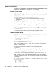
...and resume operation, do not set on the power switch. 60 ThinkPad T510, T510i, and W510 Hardware Maintenance Manual Sleep (standby) mode When the computer enters sleep (standby) mode, the following : v Press the Fn key. v If the battery indicator blinks orange, indicating that time. v Open the LCD cover... operation, press any operation with the keyboard, the TrackPoint, the hard disk, the parallel connector, or the diskette drive within that the battery power is powered off . v The CPU stops. Select Power off . In certain circumstances, the computer goes into screen blank mode, do...
...and resume operation, do not set on the power switch. 60 ThinkPad T510, T510i, and W510 Hardware Maintenance Manual Sleep (standby) mode When the computer enters sleep (standby) mode, the following : v Press the Fn key. v If the battery indicator blinks orange, indicating that time. v Open the LCD cover... operation, press any operation with the keyboard, the TrackPoint, the hard disk, the parallel connector, or the diskette drive within that the battery power is powered off . v The CPU stops. Select Power off . In certain circumstances, the computer goes into screen blank mode, do...
User Manual
Page 72
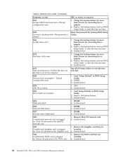
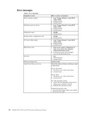
... checksum bad- System board. 02F0 CPU ID:xx Failed. 1. CPU. 2. DIMM. 2. in BIOS Setup Utility. 2. System board. 64 ThinkPad T510, T510i, and W510 Hardware Maintenance Manual System board. 0270 Real-time clock error. 1. Default configuration used . 1. System board. 02F4 EISA CMOS...1802 Unauthorized network card is cleared. System board. 02F6 Software NMI failed 1. DIMM. 2. Table 2. DIMM. 3. Replace the backup battery and run BIOS Setup Utility to reset the time and date. 0252 Password checksum bad-The password is plugged in BIOS Setup Utility. ...
... checksum bad- System board. 02F0 CPU ID:xx Failed. 1. CPU. 2. DIMM. 2. in BIOS Setup Utility. 2. System board. 64 ThinkPad T510, T510i, and W510 Hardware Maintenance Manual System board. 0270 Real-time clock error. 1. Default configuration used . 1. System board. 02F4 EISA CMOS...1802 Unauthorized network card is cleared. System board. 02F6 Software NMI failed 1. DIMM. 2. Table 2. DIMM. 3. Replace the backup battery and run BIOS Setup Utility to reset the time and date. 0252 Password checksum bad-The password is plugged in BIOS Setup Utility. ...
User Manual
Page 74
...the BIOS Setup Utility. 2. Load "Setup Defaults" in sequence 1. DIMM. 2. Load "Setup Defaults" in the BIOS Setup Utility. 2. Backup battery. 3. System board. Device Error. 1. Allocation error for device. Fan error. System board. 1. System board. Check the status of device ... v Enter the BIOS Setup Utility and add the device in boot order. 66 ThinkPad T510, T510i, and W510 Hardware Maintenance Manual Thermal sensing error. DIMM. 2. No valid operating system. 1. Backup battery. 3. The device you want to what it was before the computer entered hibernation ...
...the BIOS Setup Utility. 2. Load "Setup Defaults" in sequence 1. DIMM. 2. Load "Setup Defaults" in the BIOS Setup Utility. 2. Backup battery. 3. System board. Device Error. 1. Allocation error for device. Fan error. System board. 1. System board. Check the status of device ... v Enter the BIOS Setup Utility and add the device in boot order. 66 ThinkPad T510, T510i, and W510 Hardware Maintenance Manual Thermal sensing error. DIMM. 2. No valid operating system. 1. Backup battery. 3. The device you want to what it was before the computer entered hibernation ...

User Manual
Page 94
To remove the SIM card, you need to remove the battery pack first. (See "1010 Battery pack" on page 87.) After you finish the servicing, make sure that you are servicing has the SIM card, remove it before you start the servicing. Before servicing ThinkPad T510, T510i, and W510 Table 9. Removal steps of SIM card Some models of the ThinkPad T510, T510i, and W510 you insert the card back into the slot firmly. 86 ThinkPad T510, T510i, and W510 Hardware Maintenance Manual If the computer you are servicing might have the SIM card that the customer has installed.
To remove the SIM card, you need to remove the battery pack first. (See "1010 Battery pack" on page 87.) After you finish the servicing, make sure that you are servicing has the SIM card, remove it before you start the servicing. Before servicing ThinkPad T510, T510i, and W510 Table 9. Removal steps of SIM card Some models of the ThinkPad T510, T510i, and W510 you insert the card back into the slot firmly. 86 ThinkPad T510, T510i, and W510 Hardware Maintenance Manual If the computer you are servicing might have the SIM card that the customer has installed.

User Manual
Page 96
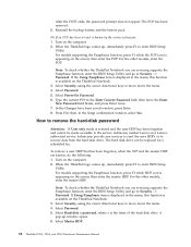
Removal steps of Serial Ultrabay Enhanced device or travel bezel Holding the bay lock latch in the direction shown by arrow 3 . 1 2 3 88 ThinkPad T510, T510i, and W510 Hardware Maintenance Manual 1020 Serial Ultrabay Enhanced device or travel bezel in the unlocked position 1 , slide the bay eject latch 2 , and then pull out the Serial Ultrabay Enhanced device or the travel bezel For access, remove this FRU: v "1010 Battery pack" on page 87 Table 11.
Removal steps of Serial Ultrabay Enhanced device or travel bezel Holding the bay lock latch in the direction shown by arrow 3 . 1 2 3 88 ThinkPad T510, T510i, and W510 Hardware Maintenance Manual 1020 Serial Ultrabay Enhanced device or travel bezel in the unlocked position 1 , slide the bay eject latch 2 , and then pull out the Serial Ultrabay Enhanced device or the travel bezel For access, remove this FRU: v "1010 Battery pack" on page 87 Table 11.

User Manual
Page 98
...: Insert the notched end of DIMM (bottom slot) a b 1 2 1 Note: If only one DIMM is firmly fixed in the slot and does not move easily. 90 ThinkPad T510, T510i, and W510 Hardware Maintenance Manual 1040 DIMM (bottom slot) For access, remove these FRUs in SLOT-1 ( b ). Removal steps of the DIMM into the place..., and pivot it until it is used on the computer you are servicing, the card must be installed in SLOT-0 ( a ), but not in order: v "1010 Battery pack" on page 87 v "1030 DIMM slot cover" on page 89 Table 13. Make sure that it snaps into the socket.
...: Insert the notched end of DIMM (bottom slot) a b 1 2 1 Note: If only one DIMM is firmly fixed in the slot and does not move easily. 90 ThinkPad T510, T510i, and W510 Hardware Maintenance Manual 1040 DIMM (bottom slot) For access, remove these FRUs in SLOT-1 ( b ). Removal steps of the DIMM into the place..., and pivot it until it is used on the computer you are servicing, the card must be installed in SLOT-0 ( a ), but not in order: v "1010 Battery pack" on page 87 v "1030 DIMM slot cover" on page 89 Table 13. Make sure that it snaps into the socket.

User Manual
Page 106
Removal steps of the arrow. 1080 PCI Express Mini Card for wireless LAN For access, remove these FRUs in direction of PCI Express Mini Card for wireless LAN In step 1 , unplug the jacks by using the removal tool antenna RF connector (P/N: 08K7159) or pick the connectors with your fingers and gently unplug them in order: v "1010 Battery pack" on page 87 v "1030 DIMM slot cover" on page 89 v "1060 Keyboard" on page 93 Table 20. Note: Some models might have only two antenna cables in step 1 . 1 1 1 98 ThinkPad T510, T510i, and W510 Hardware Maintenance Manual
Removal steps of the arrow. 1080 PCI Express Mini Card for wireless LAN For access, remove these FRUs in direction of PCI Express Mini Card for wireless LAN In step 1 , unplug the jacks by using the removal tool antenna RF connector (P/N: 08K7159) or pick the connectors with your fingers and gently unplug them in order: v "1010 Battery pack" on page 87 v "1030 DIMM slot cover" on page 89 v "1060 Keyboard" on page 93 Table 20. Note: Some models might have only two antenna cables in step 1 . 1 1 1 98 ThinkPad T510, T510i, and W510 Hardware Maintenance Manual
User Manual
Page 114
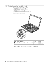
Removal steps of BDC-2.1 1 2 Step 1 Screw (quantity) M2 × 3 mm, wafer-head, nylon-coated (1) Color Silver Torque 0.181 Nm (1.85 kgfcm) When installing: Make sure that the connector is attached firmly. 106 ThinkPad T510, T510i, and W510 Hardware Maintenance Manual 1110 Bluetooth daughter card (BDC-2.1) For access, remove these FRUs in order: v "1010 Battery pack" on page 87 v "1030 DIMM slot cover" on page 89 v "1060 Keyboard" on page 93 v "1100 Keyboard bezel assembly" on page 103 Table 24.
Removal steps of BDC-2.1 1 2 Step 1 Screw (quantity) M2 × 3 mm, wafer-head, nylon-coated (1) Color Silver Torque 0.181 Nm (1.85 kgfcm) When installing: Make sure that the connector is attached firmly. 106 ThinkPad T510, T510i, and W510 Hardware Maintenance Manual 1110 Bluetooth daughter card (BDC-2.1) For access, remove these FRUs in order: v "1010 Battery pack" on page 87 v "1030 DIMM slot cover" on page 89 v "1060 Keyboard" on page 93 v "1100 Keyboard bezel assembly" on page 103 Table 24.

User Manual
Page 116
Removal steps of Smart Card 3 3 4 1 2 Step 3 Screw (quantity) M2 × 3 mm, wafer-head, nylon-coated (4) Color Silver Torque 0.181 Nm (1.85 kgfcm) 108 ThinkPad T510, T510i, and W510 Hardware Maintenance Manual 1130 Smart Card or Contactless Smart Card or Smart Card dummy spacer For access, remove these FRUs in order: v "1010 Battery pack" on page 87 v "1030 DIMM slot cover" on page 89 v "1060 Keyboard" on page 93 v "1100 Keyboard bezel assembly" on page 103 Table 26.
Removal steps of Smart Card 3 3 4 1 2 Step 3 Screw (quantity) M2 × 3 mm, wafer-head, nylon-coated (4) Color Silver Torque 0.181 Nm (1.85 kgfcm) 108 ThinkPad T510, T510i, and W510 Hardware Maintenance Manual 1130 Smart Card or Contactless Smart Card or Smart Card dummy spacer For access, remove these FRUs in order: v "1010 Battery pack" on page 87 v "1030 DIMM slot cover" on page 89 v "1060 Keyboard" on page 93 v "1100 Keyboard bezel assembly" on page 103 Table 26.

User Manual
Page 124
... access, remove these FRUs in the direction shown by arrow 1 to secure the CPU. 116 ThinkPad T510, T510i, and W510 Hardware Maintenance Manual When you service the CPU, avoid any kind of the screw in order: v "1010 Battery pack" on page 87 v "1030 DIMM slot cover" on page 89 v "1060 Keyboard" on page...
... access, remove these FRUs in the direction shown by arrow 1 to secure the CPU. 116 ThinkPad T510, T510i, and W510 Hardware Maintenance Manual When you service the CPU, avoid any kind of the screw in order: v "1010 Battery pack" on page 87 v "1030 DIMM slot cover" on page 89 v "1060 Keyboard" on page...
User Manual
Page 132
Removal steps of I /O sub card For access, remove these FRUs in order: v "1010 Battery pack" on page 87 v "1020 Serial Ultrabay Enhanced device or travel bezel" on page 88 v ...page 101 v "1100 Keyboard bezel assembly" on page 103 v "1110 Bluetooth daughter card (BDC-2.1)" on page 106 v "1120 Backup battery" on page 107 v "1130 Smart Card or Contactless Smart Card or Smart Card dummy spacer" on page 108 v "1140 Speaker assembly"... Silver Torque 0.181 Nm (1.85 kgfcm) When installing: Make sure that the connector is attached firmly. 124 ThinkPad T510, T510i, and W510 Hardware Maintenance Manual
Removal steps of I /O sub card For access, remove these FRUs in order: v "1010 Battery pack" on page 87 v "1020 Serial Ultrabay Enhanced device or travel bezel" on page 88 v ...page 101 v "1100 Keyboard bezel assembly" on page 103 v "1110 Bluetooth daughter card (BDC-2.1)" on page 106 v "1120 Backup battery" on page 107 v "1130 Smart Card or Contactless Smart Card or Smart Card dummy spacer" on page 108 v "1140 Speaker assembly"... Silver Torque 0.181 Nm (1.85 kgfcm) When installing: Make sure that the connector is attached firmly. 124 ThinkPad T510, T510i, and W510 Hardware Maintenance Manual

User Manual
Page 138
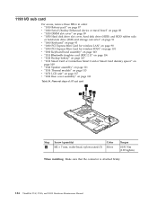
2020 LED sub card For access, remove these FRUs in this figure. 130 ThinkPad T510, T510i, and W510 Hardware Maintenance Manual Removal steps of LED sub card Note: Some models do not have connector 1a . 2 1a 1 When installing: Make sure that the connectors are attached firmly and the card is installed as shown in order: v "1010 Battery pack" on page 87 v "2010 LCD bezel assembly" on page 129 Table 38.
2020 LED sub card For access, remove these FRUs in this figure. 130 ThinkPad T510, T510i, and W510 Hardware Maintenance Manual Removal steps of LED sub card Note: Some models do not have connector 1a . 2 1a 1 When installing: Make sure that the connectors are attached firmly and the card is installed as shown in order: v "1010 Battery pack" on page 87 v "2010 LCD bezel assembly" on page 129 Table 38.

User Manual
Page 140
... In step 1 , release the antenna cables from the left and right hinges. 1 1 132 ThinkPad T510, T510i, and W510 Hardware Maintenance Manual 2040 LCD cable, camera cable, LCD panel, and hinges For access, remove these FRUs in order: v "1010 Battery pack" on page 87 v "1030 DIMM slot cover" on page 89 v "1050 Hard disk...
... In step 1 , release the antenna cables from the left and right hinges. 1 1 132 ThinkPad T510, T510i, and W510 Hardware Maintenance Manual 2040 LCD cable, camera cable, LCD panel, and hinges For access, remove these FRUs in order: v "1010 Battery pack" on page 87 v "1030 DIMM slot cover" on page 89 v "1050 Hard disk...

User Manual
Page 148
Bottom view 1 2 3 4 5 6 7 8 Battery pack Battery pack latch Docking connector Solid state drive (SSD) or hard disk drive (HDD) slot DIMM slot (bottom) LCD cover latch Serial Ultrabay Enhanced lock latch Serial Ultrabay Enhanced eject latch 8 7 1 2 3 6 5 4 140 ThinkPad T510, T510i, and W510 Hardware Maintenance Manual
Bottom view 1 2 3 4 5 6 7 8 Battery pack Battery pack latch Docking connector Solid state drive (SSD) or hard disk drive (HDD) slot DIMM slot (bottom) LCD cover latch Serial Ultrabay Enhanced lock latch Serial Ultrabay Enhanced eject latch 8 7 1 2 3 6 5 4 140 ThinkPad T510, T510i, and W510 Hardware Maintenance Manual

