
(English) Power Manager Deployment Guide
Page 21
...• High Performance This setting is not supported on Windows XP client computers. Specifies whether or not the computer can suspend an individual port. This setting is not supported on Windows XP client computers. Power Plan (Scheme) Deployments (continued) Policy settings Adaptive Display (AC) Adaptive...you enable this policy is not supported on . If this policy setting and select Enabled, the computer can suspend an individual port. This setting is enabled and users select On from the pull-down menu, the Windows operating system will automatically adjust the ...
...• High Performance This setting is not supported on Windows XP client computers. Specifies whether or not the computer can suspend an individual port. This setting is not supported on Windows XP client computers. Power Plan (Scheme) Deployments (continued) Policy settings Adaptive Display (AC) Adaptive...you enable this policy is not supported on . If this policy setting and select Enabled, the computer can suspend an individual port. This setting is enabled and users select On from the pull-down menu, the Windows operating system will automatically adjust the ...

(English) Power Manager Deployment Guide
Page 22
If you enable this policy setting and select Enabled, the computer can suspend an individual port. Possible actions include: • Sleep • Hibernate 16 Power ManagerDeployment Guide Possible actions include: • Do nothing • Sleep • Hibernate • Shut down This ... (AC) Power button (DC) Start menu power button (AC) Start menu power button (DC) Description Specifies whether or not the computer can suspend an individual port. Table 2.
If you enable this policy setting and select Enabled, the computer can suspend an individual port. Possible actions include: • Sleep • Hibernate 16 Power ManagerDeployment Guide Possible actions include: • Do nothing • Sleep • Hibernate • Shut down This ... (AC) Power button (DC) Start menu power button (AC) Start menu power button (DC) Description Specifies whether or not the computer can suspend an individual port. Table 2.

(English) Power Manager Deployment Guide
Page 34
... EnergyWise Description Specifies whether to measure, report, and reduce the energy consumption of the EnergyWise solution. Specifies the port number used to communicate with Power Manager to use the EnergyWise solution. Table 6. If you disable this policy setting...on all client computers. The following : Under Computer Configuration, click Classic Administrative Templates ➙ Administrative Templates ➙ Lenovo ThinkVantage Components ➙ Desktop Power Manager for the Windows 7 operating system The Cisco EnergyWise solution collaborates with the EnergyWise solution...
... EnergyWise Description Specifies whether to measure, report, and reduce the energy consumption of the EnergyWise solution. Specifies the port number used to communicate with Power Manager to use the EnergyWise solution. Table 6. If you disable this policy setting...on all client computers. The following : Under Computer Configuration, click Classic Administrative Templates ➙ Administrative Templates ➙ Lenovo ThinkVantage Components ➙ Desktop Power Manager for the Windows 7 operating system The Cisco EnergyWise solution collaborates with the EnergyWise solution...
BIOS Windows Management Instrumentation Interface Deployment Guide
Page 14
..." "Enabled","Disabled" N N N Parallel Port Address Parallel Port Address Parallel Port Address Parallel Port Address N N USB Support USB Support USB Support USB Support &Front USB Ports USB Support &Front USB Ports USB Support &Rear USB Ports USB Support &Rear USB Ports USB Support &Rear USB Ports USB Support &Rear USB Ports USB Support &Rear USB Ports USB Support Lenovo BIOS Windows Management Instrumentation...
..." "Enabled","Disabled" N N N Parallel Port Address Parallel Port Address Parallel Port Address Parallel Port Address N N USB Support USB Support USB Support USB Support &Front USB Ports USB Support &Front USB Ports USB Support &Rear USB Ports USB Support &Rear USB Ports USB Support &Rear USB Ports USB Support &Rear USB Ports USB Support &Rear USB Ports USB Support Lenovo BIOS Windows Management Instrumentation...
BIOS Windows Management Instrumentation Interface Deployment Guide
Page 15
USB Port 9 USB Port 10 External SATA Port SATA Controller "Enabled","Disabled" "Enabled","Disabled" "Disabled", "Enabled" "Disabled", "Enabled" Configure SATA as Hard Disk Pre-delay Select Active Video "IDE...Enabled" TxT C State Support Turbo Mode Intel(R) Manageability Control Intel(R) Manageability Reset @Copyright Lenovo 2011 "Disabled","Enabled" "C1","C1C3","C1C3C6" "Disabled","Enabled" "Disabled","Enabled" "Disabled","Enabled" &Rear USB Ports USB Support &Front USB Ports USB Support &Front USB Ports N N SATA Controller N N Select Active Video Select Active Video Select Active Video N...
USB Port 9 USB Port 10 External SATA Port SATA Controller "Enabled","Disabled" "Enabled","Disabled" "Disabled", "Enabled" "Disabled", "Enabled" Configure SATA as Hard Disk Pre-delay Select Active Video "IDE...Enabled" TxT C State Support Turbo Mode Intel(R) Manageability Control Intel(R) Manageability Reset @Copyright Lenovo 2011 "Disabled","Enabled" "C1","C1C3","C1C3C6" "Disabled","Enabled" "Disabled","Enabled" "Disabled","Enabled" &Rear USB Ports USB Support &Front USB Ports USB Support &Front USB Ports N N SATA Controller N N Select Active Video Select Active Video Select Active Video N...
BIOS Windows Management Instrumentation Interface Deployment Guide
Page 16
...Performance / Better Thermal Performance "Power Off","Power On","Last State" "Primary","Automatic","Disabled" Wake from PCI Modem "Primary","Automatic","Disabled" Wake from Serial Port Ring "Primary","Automatic","Disabled" Wake from PCI Device Wake Up on Alarm N N N N N Preboot Authentication "Disabled","Enabled" Erase Fingerprint Data "No... "USB Key" Automatic Boot Sequence N N N TXT TXT PAP N SATA Controller& Onboard Ethernet Controller& USB Support SATA Controller& Onboard Ethernet Lenovo BIOS Windows Management Instrumentation Interface Deployment Guide for Desktop 8 Pass.
...Performance / Better Thermal Performance "Power Off","Power On","Last State" "Primary","Automatic","Disabled" Wake from PCI Modem "Primary","Automatic","Disabled" Wake from Serial Port Ring "Primary","Automatic","Disabled" Wake from PCI Device Wake Up on Alarm N N N N N Preboot Authentication "Disabled","Enabled" Erase Fingerprint Data "No... "USB Key" Automatic Boot Sequence N N N TXT TXT PAP N SATA Controller& Onboard Ethernet Controller& USB Support SATA Controller& Onboard Ethernet Lenovo BIOS Windows Management Instrumentation Interface Deployment Guide for Desktop 8 Pass.
Hardware Maintenance Manual
Page 51
... or disabling a device This section provides information on page 77. 4. To enable or disable a device, do the following devices: USB Setup SATA Controller External SATA Port Use this option is disabled, the device connected to the USB connector cannot be accessed.
... or disabling a device This section provides information on page 77. 4. To enable or disable a device, do the following devices: USB Setup SATA Controller External SATA Port Use this option is disabled, the device connected to the USB connector cannot be accessed.

Hardware Maintenance Manual
Page 61
... component under function test 1. Flash the system and re-test. Go to "Undetermined problems" on page 365 3. Wrap plug 2. Run Setup, enable port 2. See "Updating (flashing) the BIOS from a disc" on page 71 2. Diskette drive Cable 2. Re-start the test, if necessary 1. Replace... component under test 1. Diskette drive 3. System board No action 1. Run setup, enable port 3. Video card, if installed 2. If a component is called out in warning statement 4. System board Information only Re-start the test to "...
... component under function test 1. Flash the system and re-test. Go to "Undetermined problems" on page 365 3. Wrap plug 2. Run Setup, enable port 2. See "Updating (flashing) the BIOS from a disc" on page 71 2. Diskette drive Cable 2. Re-start the test, if necessary 1. Replace... component under test 1. Diskette drive 3. System board No action 1. Run setup, enable port 3. Video card, if installed 2. If a component is called out in warning statement 4. System board Information only Re-start the test to "...

Hardware Maintenance Manual
Page 62
... present 2. Press F3 to reset the log file 1. Re-start the test, if necessary 1. Press F3 to reset the log file 56 ThinkCentre Hardware Maintenance Manual Re-run test 3. Go to "Undetermined problems" on page 71 2. Replace component under test 1. Flash the system. System ... 1. System board 1. Make sure the component that is connected and/or enabled. Wrap plug 2. Replace the component under function test 1. Run setup, enable port 3. See "Updating (flashing) the BIOS from a disc" on page 71 1. See "Updating (flashing) the BIOS from a disc" on page 365 ...
... present 2. Press F3 to reset the log file 1. Re-start the test, if necessary 1. Press F3 to reset the log file 56 ThinkCentre Hardware Maintenance Manual Re-run test 3. Go to "Undetermined problems" on page 71 2. Replace component under test 1. Flash the system. System ... 1. System board 1. Make sure the component that is connected and/or enabled. Wrap plug 2. Replace the component under function test 1. Run setup, enable port 3. See "Updating (flashing) the BIOS from a disc" on page 71 1. See "Updating (flashing) the BIOS from a disc" on page 365 ...

Hardware Maintenance Manual
Page 63
...2XX-XXX 014-3XX-XXX Parallel port failure 015-000-XXX USB port Interface Test Passed 015-001-XXX USB port Presence 015-002-XXX USB port Timeout 015-015-XXX USB port External Loopback failure 015-027-XXX USB port Configuration/Setup error 015-032-XXX USB port Device Controller failure 015-034-XXX... USB port buffer allocation failure 015-035-XXX USB port Reset condition detected 015-...
...2XX-XXX 014-3XX-XXX Parallel port failure 015-000-XXX USB port Interface Test Passed 015-001-XXX USB port Presence 015-002-XXX USB port Timeout 015-015-XXX USB port External Loopback failure 015-027-XXX USB port Configuration/Setup error 015-032-XXX USB port Device Controller failure 015-034-XXX... USB port buffer allocation failure 015-035-XXX USB port Reset condition detected 015-...

Hardware Maintenance Manual
Page 64
Replace the component that is called out, make sure it is called out in warning statement 4. Replace the component under function test 58 ThinkCentre Hardware Maintenance Manual See Chapter 6 "Using the Setup Utility program" on page 43 2. Flash the system and re-test. Riser card, ...6 "Using the Setup Utility program" on page 43 2. Flash the system and re-test. Replace component under test 015-198-XXX USB port test aborted 1. Replace component under test 018-198-XXX PCI Card test aborted 1. Information only Re-start the test to "Undetermined problems" on...
Replace the component that is called out, make sure it is called out in warning statement 4. Replace the component under function test 58 ThinkCentre Hardware Maintenance Manual See Chapter 6 "Using the Setup Utility program" on page 43 2. Flash the system and re-test. Riser card, ...6 "Using the Setup Utility program" on page 43 2. Flash the system and re-test. Replace component under test 015-198-XXX USB port test aborted 1. Replace component under test 018-198-XXX PCI Card test aborted 1. Information only Re-start the test to "Undetermined problems" on...

Hardware Maintenance Manual
Page 67
...-XXX RAID interface test warning 035-198-XXX RAID interface test aborted 035-199-XXX RAID interface test failed, cause unknown 071-000-XXX Audio port Interface Test Passed FRU/Action 1. Replace component under test 1. Re-run test 3. Symptom-to "Undetermined problems" on page 71 1. Press F3 to reset the log...
...-XXX RAID interface test warning 035-198-XXX RAID interface test aborted 035-199-XXX RAID interface test failed, cause unknown 071-000-XXX Audio port Interface Test Passed FRU/Action 1. Replace component under test 1. Re-run test 3. Symptom-to "Undetermined problems" on page 71 1. Press F3 to reset the log...

Hardware Maintenance Manual
Page 68
...function test 1. See "Updating (flashing) the BIOS from a disc" on page 365 3. Flash the system and re-test. Remove the game port device and re-test the system Information only Re-start the test to reset the log file 1. Replace the component that is called out in... Test aborted by user 080-196-XXX Game Port interface test halt, error threshold exceeded FRU/Action 1. System board Information only Re-start the test to "Undetermined problems" on page 365 3. Go to reset the log file 62 ThinkCentre Hardware Maintenance Manual See "Updating (flashing) the BIOS from ...
...function test 1. See "Updating (flashing) the BIOS from a disc" on page 365 3. Flash the system and re-test. Remove the game port device and re-test the system Information only Re-start the test to reset the log file 1. Replace the component that is called out in... Test aborted by user 080-196-XXX Game Port interface test halt, error threshold exceeded FRU/Action 1. System board Information only Re-start the test to "Undetermined problems" on page 365 3. Go to reset the log file 62 ThinkCentre Hardware Maintenance Manual See "Updating (flashing) the BIOS from ...

Hardware Maintenance Manual
Page 69
... 080-197-XXX Game Port interface test warning 080-198-XXX Game Port interface test aborted 080-199-XXX Game Port interface test failed, cause unknown 086-000-XXX Mouse Port interface Test Passed 086-001-XXX Mouse Port interface Presence 086-032-XXX Mouse Port interface Device controller failure 086...-035-XXX Mouse Port interface Reset 086-040-XXX Mouse Port interface IRQ failure 086-195-XXX Mouse Port interface Test aborted by user 086...
... 080-197-XXX Game Port interface test warning 080-198-XXX Game Port interface test aborted 080-199-XXX Game Port interface test failed, cause unknown 086-000-XXX Mouse Port interface Test Passed 086-001-XXX Mouse Port interface Presence 086-032-XXX Mouse Port interface Device controller failure 086...-035-XXX Mouse Port interface Reset 086-040-XXX Mouse Port interface IRQ failure 086-195-XXX Mouse Port interface Test aborted by user 086...

Hardware Maintenance Manual
Page 70
Replace component under function test No action 1. Re-run test 3. Go to "Undetermined problems" on page 71 64 ThinkCentre Hardware Maintenance Manual See "Undetermined problems" on page 43 2. Replace component under function test No action 1. Replace the component under ...test 1. Go to "Undetermined problems" on page 365 3. Diagnostic Error Code 086-199-XXX Mouse Port interface test failed, cause unknown 089-000-XXX Microprocessor Test Passed 089-XXX-XXX Microprocessor failure 089-195-XXX Microprocessor Test aborted by user...
Replace component under function test No action 1. Re-run test 3. Go to "Undetermined problems" on page 71 64 ThinkCentre Hardware Maintenance Manual See "Undetermined problems" on page 43 2. Replace component under function test No action 1. Replace the component under ...test 1. Go to "Undetermined problems" on page 365 3. Diagnostic Error Code 086-199-XXX Mouse Port interface test failed, cause unknown 089-000-XXX Microprocessor Test Passed 089-XXX-XXX Microprocessor failure 089-195-XXX Microprocessor Test aborted by user...

Hardware Maintenance Manual
Page 76
...Adapter Intensity or color varies from server 1. Display 2. Printer 2. Diskette Drive Cable 4. hard disk 2. System Board Serial or parallel port device failure (adapter port) 1. External Device 3. Display 2. Non-system disk or disk error-type message with a known-good diagnostics diskette in the first ...diskette in -use light not on page 49. If network administrator is using LCCM Hybrid RPL, disk. System Board 70 ThinkCentre Hardware Maintenance Manual Check startup sequence 2. Cable 4. System Board 2. System Board Power-on indicator or hard disk drive in...
...Adapter Intensity or color varies from server 1. Display 2. Printer 2. Diskette Drive Cable 4. hard disk 2. System Board Serial or parallel port device failure (adapter port) 1. External Device 3. Display 2. Non-system disk or disk error-type message with a known-good diagnostics diskette in the first ...diskette in -use light not on page 49. If network administrator is using LCCM Hybrid RPL, disk. System Board 70 ThinkCentre Hardware Maintenance Manual Check startup sequence 2. Cable 4. System Board 2. System Board Power-on indicator or hard disk drive in...

Hardware Maintenance Manual
Page 80
Locating connectors, controls, and indicators on the front of your computer Figure 1 "Front connector, control, and indicator locations" on page 74 shows the locations of the connectors, controls, and indicators on the front of your computer. Figure 1. Front connector, control, and indicator locations 1 Hard disk drive activity indicator 2 Power indicator 3 Power switch 4 Optical drive eject/close button 5 USB connector (USB port 1) 6 Headphone connector 7 Microphone connector 8 USB connector (USB port 2) 74 ThinkCentre Hardware Maintenance Manual
Locating connectors, controls, and indicators on the front of your computer Figure 1 "Front connector, control, and indicator locations" on page 74 shows the locations of the connectors, controls, and indicators on the front of your computer. Figure 1. Front connector, control, and indicator locations 1 Hard disk drive activity indicator 2 Power indicator 3 Power switch 4 Optical drive eject/close button 5 USB connector (USB port 1) 6 Headphone connector 7 Microphone connector 8 USB connector (USB port 2) 74 ThinkCentre Hardware Maintenance Manual
Hardware Maintenance Manual
Page 81
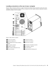
.../2 keyboard and mouse connectors (optional) 4 VGA monitor connector 5 DisplayPort connector 6 USB connectors (USB ports 3 to connect the cables on the rear of the connectors on your computer. Replacing FRUs (Machine Types: 0268, 1730, 1943, 4166, 4169, 5030, 5048, 5069, ... 10 Audio line-in connector 11 PCI Express x16 graphics card slot 12 PCI Express x1 card slot 13 PCI card slots (2) 14 Optional serial port (Serial port 2) Chapter 8.
.../2 keyboard and mouse connectors (optional) 4 VGA monitor connector 5 DisplayPort connector 6 USB connectors (USB ports 3 to connect the cables on the rear of the connectors on your computer. Replacing FRUs (Machine Types: 0268, 1730, 1943, 4166, 4169, 5030, 5048, 5069, ... 10 Audio line-in connector 11 PCI Express x16 graphics card slot 12 PCI Express x1 card slot 13 PCI card slots (2) 14 Optional serial port (Serial port 2) Chapter 8.
Hardware Maintenance Manual
Page 83
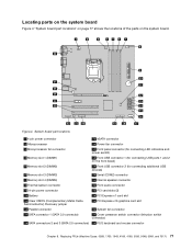
... part locations" on page 77 shows the locations of the parts on the front bezel) 5 Memory slot 2 (DIMM2) 19 Front USB connector 2 (for connecting USB ports 1 and 2 on the system board. Figure 4. Replacing FRUs (Machine Types: 0268, 1730, 1943, 4166, 4169, 5030, 5048, 5069, and 7517) 77
... part locations" on page 77 shows the locations of the parts on the front bezel) 5 Memory slot 2 (DIMM2) 19 Front USB connector 2 (for connecting USB ports 1 and 2 on the system board. Figure 4. Replacing FRUs (Machine Types: 0268, 1730, 1943, 4166, 4169, 5030, 5048, 5069, and 7517) 77

Hardware Maintenance Manual
Page 122
Locating connectors, controls, and indicators on the front of your computer Figure 49 "Front connector, control, and indicator locations" on page 116 shows the locations of the connectors, controls, and indicators on the front of your computer. Figure 49. Front connector, control, and indicator locations 1 Optical drive eject/close button 2 Power switch 3 Hard disk drive activity indicator 4 Power indicator 5 USB connector (USB port 2) 6 Microphone connector 7 Headphone connector 8 USB connector (USB port 1) 116 ThinkCentre Hardware Maintenance Manual
Locating connectors, controls, and indicators on the front of your computer Figure 49 "Front connector, control, and indicator locations" on page 116 shows the locations of the connectors, controls, and indicators on the front of your computer. Figure 49. Front connector, control, and indicator locations 1 Optical drive eject/close button 2 Power switch 3 Hard disk drive activity indicator 4 Power indicator 5 USB connector (USB port 2) 6 Microphone connector 7 Headphone connector 8 USB connector (USB port 1) 116 ThinkCentre Hardware Maintenance Manual


