Hardware Maintenance Manual
Page 3
... the optical drive . . . 86 Installing or replacing the card reader . . . . 88 Replacing the battery 92 Replacing the power supply assembly . . . 93 Replacing the heat sink and fan assembly . . 95 Replacing the microprocessor 97 © Copyright Lenovo 2011, 2012 i Contents Chapter 1. Safety information 3 General safety 3 Electrical safety 3 Voltage-selection switch 5 Safety inspection guide 5 Handling...
... the optical drive . . . 86 Installing or replacing the card reader . . . . 88 Replacing the battery 92 Replacing the power supply assembly . . . 93 Replacing the heat sink and fan assembly . . 95 Replacing the microprocessor 97 © Copyright Lenovo 2011, 2012 i Contents Chapter 1. Safety information 3 General safety 3 Electrical safety 3 Voltage-selection switch 5 Safety inspection guide 5 Handling...
Hardware Maintenance Manual
Page 4
...battery 133 Replacing the hard disk drive 134 Replacing the optical drive 137 Replacing the heat sink and fan assembly . . 139 Replacing the power supply assembly . . . 142 Replacing the microprocessor 147 Replacing the system board 150 Replacing the system fan assembly . . . . 153 ...4167, 5025, 5032, 5049, 5070, and 7518 163 Mechanical FRUs 178 Keyboard and Mouse 185 Adapters and miscellaneous FRUs 228 Power Cords 232 Recovery discs 241 ii ThinkCentre Hardware Maintenance Manual Windows 7 Home Premium 32 Recovery CD 241 Windows 7 Professional 32 Recovery CD . . 244 Windows 7 ...
...battery 133 Replacing the hard disk drive 134 Replacing the optical drive 137 Replacing the heat sink and fan assembly . . 139 Replacing the power supply assembly . . . 142 Replacing the microprocessor 147 Replacing the system board 150 Replacing the system fan assembly . . . . 153 ...4167, 5025, 5032, 5049, 5070, and 7518 163 Mechanical FRUs 178 Keyboard and Mouse 185 Adapters and miscellaneous FRUs 228 Power Cords 232 Recovery discs 241 ii ThinkCentre Hardware Maintenance Manual Windows 7 Home Premium 32 Recovery CD 241 Windows 7 Professional 32 Recovery CD . . 244 Windows 7 ...

Hardware Maintenance Manual
Page 10
If an electrical accident occurs, you from their equipment, rubber floor mats that another person to get medical aid. 4 ThinkCentre Hardware Maintenance Manual Remember: There must be a complete circuit to insulate you can cause personal injury and machine damage.... of mat to work alone under hazardous conditions or near you when working with very high voltages; Some hand tools have , near power supplies - Ensure that contain small conductive fibers to work area. Many customers have handles covered with a soft material that has exposed electrical ...
If an electrical accident occurs, you from their equipment, rubber floor mats that another person to get medical aid. 4 ThinkCentre Hardware Maintenance Manual Remember: There must be a complete circuit to insulate you can cause personal injury and machine damage.... of mat to work alone under hazardous conditions or near you when working with very high voltages; Some hand tools have , near power supplies - Ensure that contain small conductive fibers to work area. Many customers have handles covered with a soft material that has exposed electrical ...

Hardware Maintenance Manual
Page 12
... to protect against ESD damage. - Safety notices (multi-lingual translations) The caution and danger safety notices in charge between objects. Notes: 1. Make sure that the power-supply cover fasteners (screws or rivets) have been certified (ISO 9000) as to provide protection that the machine, the part, the work surface. Note: The use... handling ESD-sensitive parts: • Keep the parts in the following languages: • English • Arabic • Brazilian/Portuguese • Chinese (simplified) • Chinese (traditional) 6 ThinkCentre Hardware Maintenance Manual
... to protect against ESD damage. - Safety notices (multi-lingual translations) The caution and danger safety notices in charge between objects. Notes: 1. Make sure that the power-supply cover fasteners (screws or rivets) have been certified (ISO 9000) as to provide protection that the machine, the part, the work surface. Note: The use... handling ESD-sensitive parts: • Keep the parts in the following languages: • English • Arabic • Brazilian/Portuguese • Chinese (simplified) • Chinese (traditional) 6 ThinkCentre Hardware Maintenance Manual

Hardware Maintenance Manual
Page 14
...CD-ROMs, DVD-ROM drives, fiber optic devices, or transmitters) are disconnected from the power source. 2 1 8 ThinkCentre Hardware Maintenance Manual To remove all electrical current from the device, ensure that all power cords are installed, note the following : Laser radiation when open. DANGER Some laser products...;32 kg (70.5 lb) ≥55 kg (121.2 lb) CAUTION: The power control button on the device and the power switch on the power supply do not turn off the electrical current supplied to hazardous laser radiation. The device also might have more than those specified herein might...
...CD-ROMs, DVD-ROM drives, fiber optic devices, or transmitters) are disconnected from the power source. 2 1 8 ThinkCentre Hardware Maintenance Manual To remove all electrical current from the device, ensure that all power cords are installed, note the following : Laser radiation when open. DANGER Some laser products...;32 kg (70.5 lb) ≥55 kg (121.2 lb) CAUTION: The power control button on the device and the power switch on the power supply do not turn off the electrical current supplied to hazardous laser radiation. The device also might have more than those specified herein might...

Hardware Maintenance Manual
Page 53
...Better Thermal Performance By enabling Better Acoustic Performance, your setting and exit the Setup Utility program. You might have to wake up when the power supply resumes after a sudden loss of the following: • If you finish viewing or changing settings, press Esc to return to the Setup... the wake up on alarm feature The wake up on alarm feature enables your computer to save and exit the Setup Utility program. Select Power On and press Enter. 4. The Smart Performance Choice window is enabled, you can adjust the acoustic and thermal performance of the following ...
...Better Thermal Performance By enabling Better Acoustic Performance, your setting and exit the Setup Utility program. You might have to wake up when the power supply resumes after a sudden loss of the following: • If you finish viewing or changing settings, press Esc to return to the Setup... the wake up on alarm feature The wake up on alarm feature enables your computer to save and exit the Setup Utility program. Select Power On and press Enter. 4. The Smart Performance Choice window is enabled, you can adjust the acoustic and thermal performance of the following ...

Hardware Maintenance Manual
Page 55
...proper installation: • Power cord • On/Off switch connector • On/Off switch power supply connector • System board power supply connectors • Microprocessor(s) connection Check the power cord for continuity. Replace the hard disk drive. FRU/Action Reseat connectors Power cord Power-on page 37. Chapter... code when running a test, but did not receive any error message, look for information about the diagnostic programs. © Copyright Lenovo 2011, 2012 49 Hard disk drive boot error A hard disk drive boot error (error codes 1962 and I999030X) can use the ...
...proper installation: • Power cord • On/Off switch connector • On/Off switch power supply connector • System board power supply connectors • Microprocessor(s) connection Check the power cord for continuity. Replace the hard disk drive. FRU/Action Reseat connectors Power cord Power-on page 37. Chapter... code when running a test, but did not receive any error message, look for information about the diagnostic programs. © Copyright Lenovo 2011, 2012 49 Hard disk drive boot error A hard disk drive boot error (error codes 1962 and I999030X) can use the ...

Hardware Maintenance Manual
Page 65
... page 43 2. Replace the component that is called out, make sure it is called out in warning statement 4. Flash the system and re-test. Check power supply voltages 3. IDE device 5. Flash the system. System board No action 1. System board Information only Re-start the test to "Undetermined problems" on page 365 3. Go...
... page 43 2. Replace the component that is called out, make sure it is called out in warning statement 4. Flash the system and re-test. Check power supply voltages 3. IDE device 5. Flash the system. System board No action 1. System board Information only Re-start the test to "Undetermined problems" on page 365 3. Go...

Hardware Maintenance Manual
Page 66
... the log file 2. Go to "Undetermined problems" on page 365 3. SCSI signal cable 2. Check power supply 3. SCSI adapter card, if installed 5. SCSI signal cable 2. SCSI device 4. SCSI device 4. IDE device 5. Re-start the test, if necessary 60 ThinkCentre Hardware Maintenance Manual System board 1. If a component is connected and/or enabled. Go to "Undetermined...
... the log file 2. Go to "Undetermined problems" on page 365 3. SCSI signal cable 2. Check power supply 3. SCSI adapter card, if installed 5. SCSI signal cable 2. SCSI device 4. SCSI device 4. IDE device 5. Re-start the test, if necessary 60 ThinkCentre Hardware Maintenance Manual System board 1. If a component is connected and/or enabled. Go to "Undetermined...

Hardware Maintenance Manual
Page 71
...Updating (flashing) the BIOS from a disc" on page 365 3. See "Updating (flashing) the BIOS from a disc" on page 365 3. Check Power supply voltages 3. System board 1. Microprocessor 3. System board No action Chapter 7. Voltage Regulator Module (VRM) 2. Replace the component that is called out, make... Security Chassis Intrusion 201-000-XXX System Memory Test Passed FRU/Action 1. See "Undetermined problems" on page 71 1. Power supply 2. System board No action 1. See Chapter 6 "Using the Setup Utility program" on page 43 2. Replace component under function test...
...Updating (flashing) the BIOS from a disc" on page 365 3. See "Updating (flashing) the BIOS from a disc" on page 365 3. Check Power supply voltages 3. System board 1. Microprocessor 3. System board No action Chapter 7. Voltage Regulator Module (VRM) 2. Replace the component that is called out, make... Security Chassis Intrusion 201-000-XXX System Memory Test Passed FRU/Action 1. See "Undetermined problems" on page 71 1. Power supply 2. System board No action 1. See Chapter 6 "Using the Setup Utility program" on page 43 2. Replace component under function test...

Hardware Maintenance Manual
Page 72
...the system 1. System board No action Remove the Joystick and re-test the system 66 ThinkCentre Hardware Maintenance Manual System board 3. CD-ROM Drive Cable 2. Hard Disk Drive Cable 2. Check power supply voltages 3. SCSI adapter card 6. Keyboard 2. Check and test mouse 3. Replace the ... the test 2. Diskette drive 4. System board 1. Hard Disk drive (SCSI) 5. System board No action 1. Check and test Keyboard 3. Check power supply voltages 3. System board No action 1. Reseat the hard disk drive cable 4. System board No action No action 1. System board No action 1. ...
...the system 1. System board No action Remove the Joystick and re-test the system 66 ThinkCentre Hardware Maintenance Manual System board 3. CD-ROM Drive Cable 2. Hard Disk Drive Cable 2. Check power supply voltages 3. SCSI adapter card 6. Keyboard 2. Check and test mouse 3. Replace the ... the test 2. Diskette drive 4. System board 1. Hard Disk drive (SCSI) 5. System board No action 1. Check and test Keyboard 3. Check power supply voltages 3. System board No action 1. Reseat the hard disk drive cable 4. System board No action No action 1. System board No action 1. ...

Hardware Maintenance Manual
Page 75
...See "Hard disk drive boot error" on page 49. 1. Diskette Drive 2. Primary Hard Disk Drive 3. Check power supply and signal cable connections to -FRU index 69 Ensure no interrupt or I/O address conflicts 6. Hard Disk Drive Cable ...drive boot error" on page 49. 1. Network adapter (advise network administrator of new MAC address) Computer will not power-off. System Board Diskette drive in-use light remains on LAN 3. Memory Module 3. Symptom-to network adapter 2. ... card, if installed Computer will not RPL from server 1. Power Supply 2. System Board 3.
...See "Hard disk drive boot error" on page 49. 1. Diskette Drive 2. Primary Hard Disk Drive 3. Check power supply and signal cable connections to -FRU index 69 Ensure no interrupt or I/O address conflicts 6. Hard Disk Drive Cable ...drive boot error" on page 49. 1. Network adapter (advise network administrator of new MAC address) Computer will not power-off. System Board Diskette drive in-use light remains on LAN 3. Memory Module 3. Symptom-to network adapter 2. ... card, if installed Computer will not RPL from server 1. Power Supply 2. System Board 3.

Hardware Maintenance Manual
Page 76
...OK? 2. External Device 3. System Board 70 ThinkCentre Hardware Maintenance Manual Display 2. Non-system disk or disk error-type message with a known-good diagnostics diskette in the first 3.5-inch diskette drive 1. Power switch/LED assembly 2. System Board Serial or ... Board Printer problems 1. Printer 2. Run Setup and check Startup sequence. 2. Diskette Drive 3. Diskette Drive Cable 4. System Board 5. Power Supply RPL computer cannot access programs from the hard disk with a known-good diagnostic diskette. 1. check startup sequence: a. First device -...
...OK? 2. External Device 3. System Board 70 ThinkCentre Hardware Maintenance Manual Display 2. Non-system disk or disk error-type message with a known-good diagnostics diskette in the first 3.5-inch diskette drive 1. Power switch/LED assembly 2. System Board Serial or ... Board Printer problems 1. Printer 2. Run Setup and check Startup sequence. 2. Diskette Drive 3. Diskette Drive Cable 4. System Board 5. Power Supply RPL computer cannot access programs from the hard disk with a known-good diagnostic diskette. 1. check startup sequence: a. First device -...

Hardware Maintenance Manual
Page 82
... shows the locations of the various components in some models) 9 System board 10 Cover presence switch (also called intrusion switch) 11 Rear fan assembly 12 Power supply assembly 76 ThinkCentre Hardware Maintenance Manual
... shows the locations of the various components in some models) 9 System board 10 Cover presence switch (also called intrusion switch) 11 Rear fan assembly 12 Power supply assembly 76 ThinkCentre Hardware Maintenance Manual

Hardware Maintenance Manual
Page 99
...the battery, an error message might prevent your safety and proper Underwriters Laboratories (UL) certification. Replacing the power supply assembly Attention: Do not open your computer or attempt any cables that might be displayed. Chapter 8. ...ThinkCentre User Guide, go to: http://www.lenovo.com/ThinkCentreUserGuides This section provides instructions on the computer and all external cables. 3. See "Locating parts on the system board" on for the first time after the power cord has been disconnected, the following warnings are required for your access to replace the power supply...
...the battery, an error message might prevent your safety and proper Underwriters Laboratories (UL) certification. Replacing the power supply assembly Attention: Do not open your computer or attempt any cables that might be displayed. Chapter 8. ...ThinkCentre User Guide, go to: http://www.lenovo.com/ThinkCentreUserGuides This section provides instructions on the computer and all external cables. 3. See "Locating parts on the system board" on for the first time after the power cord has been disconnected, the following warnings are required for your access to replace the power supply...

Hardware Maintenance Manual
Page 100
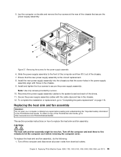
... you suspect a problem with one of these components. Disconnect the power supply assembly cables from the cable clips and ties in the chassis. 94 ThinkCentre Hardware Maintenance Manual CAUTION: Never remove the cover on a power supply or any component that has the following : 1. To replace the power supply assembly, do the following label attached. See "Locating parts...
... you suspect a problem with one of these components. Disconnect the power supply assembly cables from the cable clips and ties in the chassis. 94 ThinkCentre Hardware Maintenance Manual CAUTION: Never remove the cover on a power supply or any component that has the following : 1. To replace the power supply assembly, do the following label attached. See "Locating parts...
Hardware Maintenance Manual
Page 101
... any repair before removing the computer cover. CAUTION: The heat sink and fan assembly might be very hot. Secure the power supply assembly cables with those in the ThinkCentre User Guide. Replacing FRUs (Machine Types: 0268, 1730, 1943, 4166, 4169, 5030, 5048, 5069, and 7517)...power supply assembly. To complete the installation or replacement, go to: http://www.lenovo.com/ThinkCentreUserGuides This section provides instructions on how to "Completing the parts replacement" on its side and remove the four screws at the rear of the drives. 11. To obtain a copy of the ThinkCentre...
... any repair before removing the computer cover. CAUTION: The heat sink and fan assembly might be very hot. Secure the power supply assembly cables with those in the ThinkCentre User Guide. Replacing FRUs (Machine Types: 0268, 1730, 1943, 4166, 4169, 5030, 5048, 5069, and 7517)...power supply assembly. To complete the installation or replacement, go to: http://www.lenovo.com/ThinkCentreUserGuides This section provides instructions on how to "Completing the parts replacement" on its side and remove the four screws at the rear of the drives. 11. To obtain a copy of the ThinkCentre...

Hardware Maintenance Manual
Page 124
Component locations 1 Heat sink and fan assembly 2 Microprocessor 3 Power supply assembly 4 Memory module 5 Optical drive 6 Front audio and USB assembly 7 Front bezel 8 System fan assembly 9 Internal speaker (installed in some models) 10 Cover presence switch (... computer cover" on page 121. Locating components Figure 51 "Component locations" on page 118 shows the locations of the parts on the system board. 118 ThinkCentre Hardware Maintenance Manual
Component locations 1 Heat sink and fan assembly 2 Microprocessor 3 Power supply assembly 4 Memory module 5 Optical drive 6 Front audio and USB assembly 7 Front bezel 8 System fan assembly 9 Internal speaker (installed in some models) 10 Cover presence switch (... computer cover" on page 121. Locating components Figure 51 "Component locations" on page 118 shows the locations of the parts on the system board. 118 ThinkCentre Hardware Maintenance Manual

Hardware Maintenance Manual
Page 148
... safety and proper Underwriters Laboratories (UL) certification. 142 ThinkCentre Hardware Maintenance Manual Figure 79. To complete the installation or replacement, go to: http://www.lenovo.com/ThinkCentreUserGuides This section provides instructions on the top of the ThinkCentre User Guide, go to secure the heat sink fan ...duct. To obtain a copy of the heat sink and fan assembly until the two screw holes in the ThinkCentre User Guide. Lower and position the heat sink fan duct on how to replace the power supply assembly....
... safety and proper Underwriters Laboratories (UL) certification. 142 ThinkCentre Hardware Maintenance Manual Figure 79. To complete the installation or replacement, go to: http://www.lenovo.com/ThinkCentreUserGuides This section provides instructions on the top of the ThinkCentre User Guide, go to secure the heat sink fan ...duct. To obtain a copy of the heat sink and fan assembly until the two screw holes in the ThinkCentre User Guide. Lower and position the heat sink fan duct on how to replace the power supply assembly....

Hardware Maintenance Manual
Page 149
...the computer. See "Replacing the hard disk drive" on page 121. 3. Keep fingers and other body parts away. Then, disconnect all power cords from the drives and turn off all cables that are connected to the computer. 2. See "Opening the computer cover" on page 134... inside these parts, contact a service technician. See "Removing and reinstalling the front bezel" on a power supply or any component that has the following : 1. Remove the hard disk drive. To replace the power supply assembly, do the following label attached. Chapter 9. CAUTION: Never remove the cover on page 122. ...
...the computer. See "Replacing the hard disk drive" on page 121. 3. Keep fingers and other body parts away. Then, disconnect all power cords from the drives and turn off all cables that are connected to the computer. 2. See "Opening the computer cover" on page 134... inside these parts, contact a service technician. See "Removing and reinstalling the front bezel" on a power supply or any component that has the following : 1. Remove the hard disk drive. To replace the power supply assembly, do the following label attached. Chapter 9. CAUTION: Never remove the cover on page 122. ...


