Hardware Maintenance Manual (HMM)
Page 49
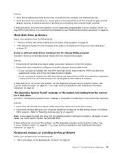
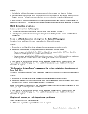
If these actions do not correct the problem, run the diagnostic program Lenovo Solution Center. If your computer is installed with five SATA hard disk drives, ensure that the SATA hard disk drive enablement module (one to five hard disk drives) or the LSI MegaRAID SAS adapter is installed...pointing device problems Select your computer starts from the Setup Utility program Actions: • Ensure that all hard disk drive signal cables and power cables are connected correctly. • Ensure that your computer is installed with the operating system might get corrupted or damaged. In such...
If these actions do not correct the problem, run the diagnostic program Lenovo Solution Center. If your computer is installed with five SATA hard disk drives, ensure that the SATA hard disk drive enablement module (one to five hard disk drives) or the LSI MegaRAID SAS adapter is installed...pointing device problems Select your computer starts from the Setup Utility program Actions: • Ensure that all hard disk drive signal cables and power cables are connected correctly. • Ensure that your computer is installed with the operating system might get corrupted or damaged. In such...
Hardware Maintenance Manual (HMM)
Page 63
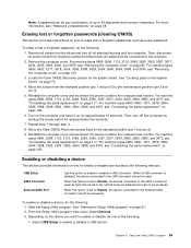
..."Completing the parts replacement" on page 117. When this feature is disabled, the device connected to the SATA connectors (such as a user password. Then, disconnect all power cords from electrical outlets and disconnect all devices connected to the USB connector cannot be accessed. To erase... a lost or forgotten passwords (clearing CMOS) This section provides instructions on page 84. Reinstall the computer cover and reconnect the power cords for the computer and monitor. Repeat step 1 through step 3. 8. Erasing lost or forgotten password, do one of up to...
..."Completing the parts replacement" on page 117. When this feature is disabled, the device connected to the SATA connectors (such as a user password. Then, disconnect all power cords from electrical outlets and disconnect all devices connected to the USB connector cannot be accessed. To erase... a lost or forgotten passwords (clearing CMOS) This section provides instructions on page 84. Reinstall the computer cover and reconnect the power cords for the computer and monitor. Repeat step 1 through step 3. 8. Erasing lost or forgotten password, do one of up to...

Hardware Maintenance Manual (HMM)
Page 64
... compliance mode in the Setup Utility program, do the following : 60 ThinkCentre Hardware Maintenance Manual Select Enabled and press Enter. 4. Select Wake on the...the startup sequence. From the Setup Utility program main menu, select Power ➙ Enhanced Power Saving Mode, and press Enter. 3. Note: When ErP compliance mode...From the Setup Utility program main menu, select Startup. 3. From the Power menu, select Automatic Power On and press Enter. 5. See "Exiting the Setup Utility program" on...Power menu in the Setup Utility program to enable or disable an internal or external...
... compliance mode in the Setup Utility program, do the following : 60 ThinkCentre Hardware Maintenance Manual Select Enabled and press Enter. 4. Select Wake on the...the startup sequence. From the Setup Utility program main menu, select Power ➙ Enhanced Power Saving Mode, and press Enter. 3. Note: When ErP compliance mode...From the Setup Utility program main menu, select Startup. 3. From the Power menu, select Automatic Power On and press Enter. 5. See "Exiting the Setup Utility program" on...Power menu in the Setup Utility program to enable or disable an internal or external...

Hardware Maintenance Manual (HMM)
Page 78
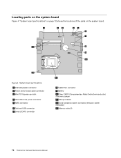
...fan connector 4 Memory slot 1 (DIMM1) 5 Memory slot 2 (DIMM2) 6 Thermal sensor connector 7 24-pin power connector 8 Power fan connector 9 Parallel connector 10 Front panel connector (for connecting LED indicators and the power switch) 11 Front USB connector 1 (for connecting an additional USB device) 14 Clear CMOS (Complementary Metal Oxide ... 20 PCI Express x1 card slots (2) 21 PCI Express x16 graphics card slot 22 System fan connector 74 ThinkCentre Hardware Maintenance Manual Figure 4 "System board part locations" on page 74 shows the locations of the parts on the front bezel) ...
...fan connector 4 Memory slot 1 (DIMM1) 5 Memory slot 2 (DIMM2) 6 Thermal sensor connector 7 24-pin power connector 8 Power fan connector 9 Parallel connector 10 Front panel connector (for connecting LED indicators and the power switch) 11 Front USB connector 1 (for connecting an additional USB device) 14 Clear CMOS (Complementary Metal Oxide ... 20 PCI Express x1 card slots (2) 21 PCI Express x16 graphics card slot 22 System fan connector 74 ThinkCentre Hardware Maintenance Manual Figure 4 "System board part locations" on page 74 shows the locations of the parts on the front bezel) ...

Hardware Maintenance Manual (HMM)
Page 79
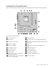
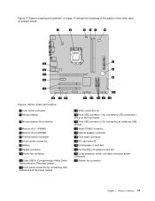
...Figure 5. Locations 75 System board part locations 1 4-pin power connector 2 Microprocessor 3 Microprocessor fan connector 4 Memory slot 1 (DIMM1) 5 Memory slot 2 (DIMM2) 6 Thermal sensor connector 7 24-pin power connector 8 Battery 9 Parallel connector 10 Power fan connector 11 Clear CMOS (Complementary Metal Oxide Semiconductor) /...Recovery jumper 12 Front panel connector (for connecting LED indicators and the power switch) 13 SATA connectors (4) 14 Front USB connector 1 (for connecting an additional USB device) 16 Serial (COM2) connector 17...
...Figure 5. Locations 75 System board part locations 1 4-pin power connector 2 Microprocessor 3 Microprocessor fan connector 4 Memory slot 1 (DIMM1) 5 Memory slot 2 (DIMM2) 6 Thermal sensor connector 7 24-pin power connector 8 Battery 9 Parallel connector 10 Power fan connector 11 Clear CMOS (Complementary Metal Oxide Semiconductor) /...Recovery jumper 12 Front panel connector (for connecting LED indicators and the power switch) 13 SATA connectors (4) 14 Front USB connector 1 (for connecting an additional USB device) 16 Serial (COM2) connector 17...

Hardware Maintenance Manual (HMM)
Page 85
... slot 1 (DIMM1) 5 Memory slot 2 (DIMM2) 6 Thermal sensor connector 7 24-pin power connector 8 Power fan connector 9 Parallel connector 10 Front panel connector (for connecting LED indicators and power switch) 11 Front USB connector 1 (for connecting USB ports 1 and 2 on the front bezel) 12 SATA connectors (4) 13 Front USB connector 2 (for connecting additional USB devices) 14...
... slot 1 (DIMM1) 5 Memory slot 2 (DIMM2) 6 Thermal sensor connector 7 24-pin power connector 8 Power fan connector 9 Parallel connector 10 Front panel connector (for connecting LED indicators and power switch) 11 Front USB connector 1 (for connecting USB ports 1 and 2 on the front bezel) 12 SATA connectors (4) 13 Front USB connector 2 (for connecting additional USB devices) 14...
Hardware Maintenance Manual (HMM)
Page 99
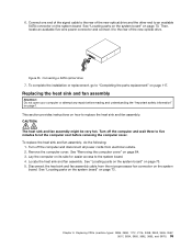
...rear of the new optical drive. Remove the computer cover. See "Locating parts on the system board" on page 84. 3. Connecting a SATA optical drive 7. Chapter 9. This section provides instructions on how to "Completing the parts replacement" on the system board. Replacing the heat sink...sink and fan assembly cable from electrical outlets. 2. 6. Locate the heat sink and fan assembly. Turn off the computer and disconnect all power cords from the microprocessor fan connector on page 117. Lay the computer on the system board. Replacing FRUs (machine types: 0896, 0958, ...
...rear of the new optical drive. Remove the computer cover. See "Locating parts on the system board" on page 84. 3. Connecting a SATA optical drive 7. Chapter 9. This section provides instructions on how to "Completing the parts replacement" on the system board. Replacing the heat sink...sink and fan assembly cable from electrical outlets. 2. 6. Locate the heat sink and fan assembly. Turn off the computer and disconnect all power cords from the microprocessor fan connector on page 117. Lay the computer on the system board. Replacing FRUs (machine types: 0896, 0958, ...

Hardware Maintenance Manual (HMM)
Page 109
... the four screws to replace the rear fan assembly. Figure 35. To complete the installation or replacement, go to an available SATA connector on page 117. Figure 34. Connecting a SATA hard disk drive 8. Chapter 9. Connect one end of the signal cable to the rear of the new hard disk drive. ...Then, locate an available five-wire power connector and connect it to the rear of the new hard disk drive and the other ...
... the four screws to replace the rear fan assembly. Figure 35. To complete the installation or replacement, go to an available SATA connector on page 117. Figure 34. Connecting a SATA hard disk drive 8. Chapter 9. Connect one end of the signal cable to the rear of the new hard disk drive. ...Then, locate an available five-wire power connector and connect it to the rear of the new hard disk drive and the other ...

Hardware Maintenance Manual (HMM)
Page 133
... drive Attention: Do not open your computer or attempt any repair before reading and understanding the "Important safety information" on page 156. Connecting a SATA hard disk drive 8. Then, install the four screws to replace the optical drive. 7. Position the new hard disk drive into the hard disk ..., 3629, 3654, 3660, 3664, 3668, and 3676) 129 Figure 67. Installing the hard disk drive 9. Figure 68. Then, locate an available five-wire power connector and connect it to the rear of the new hard disk drive and the other end to "Completing the parts replacement" on page 1. To...
... drive Attention: Do not open your computer or attempt any repair before reading and understanding the "Important safety information" on page 156. Connecting a SATA hard disk drive 8. Then, install the four screws to replace the optical drive. 7. Position the new hard disk drive into the hard disk ..., 3629, 3654, 3660, 3664, 3668, and 3676) 129 Figure 67. Installing the hard disk drive 9. Figure 68. Then, locate an available five-wire power connector and connect it to the rear of the new hard disk drive and the other end to "Completing the parts replacement" on page 1. To...

Hardware Maintenance Manual (HMM)
Page 136
... the screw holes in the new optical drive with the corresponding holes in place. Installing the optical drive 11. Figure 74. Connecting a SATA optical drive 12. Then, install the two screws to secure the new optical drive in the drive bay. To complete the installation or ...of the signal cable to "Completing the parts replacement" on page 1. CAUTION: 132 ThinkCentre Hardware Maintenance Manual See "Locating parts on the system board" on the system board. Then, locate an available five-wire power connector and connect it to the rear of the new optical drive and the other...
... the screw holes in the new optical drive with the corresponding holes in place. Installing the optical drive 11. Figure 74. Connecting a SATA optical drive 12. Then, install the two screws to secure the new optical drive in the drive bay. To complete the installation or ...of the signal cable to "Completing the parts replacement" on page 1. CAUTION: 132 ThinkCentre Hardware Maintenance Manual See "Locating parts on the system board" on the system board. Then, locate an available five-wire power connector and connect it to the rear of the new optical drive and the other...
Hardware Maintenance Manual - ThinkCentre M72e (3261, 3263, 3264, 3267, 3273, 3856, 4004, and 4156)
Page 47
... the SATA hard disk drive enablement module (one to five hard disk drives) or the LSI MegaRAID SAS adapter is installed. If these actions do not work" on page 58. Troubleshooting and diagnostics 43 Actions: • Verify that all hard disk drive signal cables and power cables are... correct hard disk drive" on the keyboard do not correct the problem, run the diagnostic program Lenovo Solution Center. If these actions do not correct the problem, run the diagnostic program Lenovo Solution Center. If these actions do not correct the problem, run the diagnostic programs (see "...
... the SATA hard disk drive enablement module (one to five hard disk drives) or the LSI MegaRAID SAS adapter is installed. If these actions do not work" on page 58. Troubleshooting and diagnostics 43 Actions: • Verify that all hard disk drive signal cables and power cables are... correct hard disk drive" on the keyboard do not correct the problem, run the diagnostic program Lenovo Solution Center. If these actions do not correct the problem, run the diagnostic program Lenovo Solution Center. If these actions do not correct the problem, run the diagnostic programs (see "...

Hardware Maintenance Manual - ThinkCentre M72e (3261, 3263, 3264, 3267, 3273, 3856, 4004, and 4156)
Page 61
... a lost or forgotten passwords, such as hard disk drives) are connected to the maintenance position (pin 2 and pin 3). 5. Then, disconnect all power cords from the standard position (pin 1 and pin 2) to the computer. 2. Remove the computer cover. Locate the Clear CMOS /Recovery jumper on ... and the computer. Repeat step 1 through step 2. 8. Reinstall the computer cover and connect the power cord. To enable or disable a device, do the following devices: USB Setup SATA Controller Use this feature is disabled, the device connected to save changes and exit the Setup Utility...
... a lost or forgotten passwords, such as hard disk drives) are connected to the maintenance position (pin 2 and pin 3). 5. Then, disconnect all power cords from the standard position (pin 1 and pin 2) to the computer. 2. Remove the computer cover. Locate the Clear CMOS /Recovery jumper on ... and the computer. Repeat step 1 through step 2. 8. Reinstall the computer cover and connect the power cord. To enable or disable a device, do the following devices: USB Setup SATA Controller Use this feature is disabled, the device connected to save changes and exit the Setup Utility...
Hardware Maintenance Manual - ThinkCentre M72e (3261, 3263, 3264, 3267, 3273, 3856, 4004, and 4156)
Page 76
... PCI Express card slot 4 Hard disk drive power connector 5 SATA connector 6 Optional USB connector 7 Serial (COM1) connector 8 System fan connector 9 Battery 10 Clear CMOS (Complementary Metal Oxide Semiconductor) /Recovery jumper 11 Microprocessor 12 Cover presence switch connector (Intrusion switch connector) 13 Memory slots (2) 72 ThinkCentre Hardware Maintenance Manual Locating parts on the system...
... PCI Express card slot 4 Hard disk drive power connector 5 SATA connector 6 Optional USB connector 7 Serial (COM1) connector 8 System fan connector 9 Battery 10 Clear CMOS (Complementary Metal Oxide Semiconductor) /Recovery jumper 11 Microprocessor 12 Cover presence switch connector (Intrusion switch connector) 13 Memory slots (2) 72 ThinkCentre Hardware Maintenance Manual Locating parts on the system...
(English) User Guide
Page 23
... fan connector 4 Memory slot 1 (DIMM1) 5 Memory slot 2 (DIMM2) 6 Thermal sensor connector 7 24-pin power connector 8 Power fan connector 9 Parallel connector 10 Front panel connector (for connecting LED indicators and power switch) 11 Front USB connector 1 (for connecting USB ports 1 and 2 on the system board. Product overview 11... Locating parts on the system board Figure 4 "System board part locations" on page 11 shows the locations of the parts on the front bezel) 12 SATA ...
... fan connector 4 Memory slot 1 (DIMM1) 5 Memory slot 2 (DIMM2) 6 Thermal sensor connector 7 24-pin power connector 8 Power fan connector 9 Parallel connector 10 Front panel connector (for connecting LED indicators and power switch) 11 Front USB connector 1 (for connecting USB ports 1 and 2 on the system board. Product overview 11... Locating parts on the system board Figure 4 "System board part locations" on page 11 shows the locations of the parts on the front bezel) 12 SATA ...

(English) User Guide
Page 55
... attempt any repair before reading and understanding the "Important safety information" on page 11. Installing or replacing hardware 43 Connecting a SATA hard disk drive 8. Then, locate an available five-wire power connector and connect it to the rear of the new hard disk drive and the other end to the rear of... the new hard disk drive. See "Locating parts on the system board" on page v. 7. Figure 25. Figure 24. Connect one end of the signal cable to an available SATA...
... attempt any repair before reading and understanding the "Important safety information" on page 11. Installing or replacing hardware 43 Connecting a SATA hard disk drive 8. Then, locate an available five-wire power connector and connect it to the rear of the new hard disk drive and the other end to the rear of... the new hard disk drive. See "Locating parts on the system board" on page v. 7. Figure 25. Figure 24. Connect one end of the signal cable to an available SATA...

(English) User Guide
Page 59
... cover" on how to do the following: 1. 11. See "Locating parts on the system board" on page v. Connecting a SATA optical drive What to replace the heat sink and fan assembly. Then, disconnect all power cords from the drives and turn off the computer and wait three to five minutes to the rear... of the new optical drive and the other end to the computer. 2. Installing or replacing hardware 47 Figure 31. Turn off all cables that are connected to an available SATA connector on...
... cover" on how to do the following: 1. 11. See "Locating parts on the system board" on page v. Connecting a SATA optical drive What to replace the heat sink and fan assembly. Then, disconnect all power cords from the drives and turn off the computer and wait three to five minutes to the rear... of the new optical drive and the other end to the computer. 2. Installing or replacing hardware 47 Figure 31. Turn off all cables that are connected to an available SATA connector on...

(English) User Guide
Page 95
... disable a USB device. • Select ATA Drive Setup to the computer. 2. Using the Setup Utility program 83 Then, disconnect all power cords from the drives and turn off all devices connected to the USB connector cannot be used. Repeat step 1 through step 3. 8. ...See "Completing the parts replacement" on page 85. Start the Setup Utility program. Press F10 to the External SATA connector cannot be accessed. Locate the Clear CMOS /Recovery jumper on page 11. 4. When this option to the maintenance position (pin 2 and ...
... disable a USB device. • Select ATA Drive Setup to the computer. 2. Using the Setup Utility program 83 Then, disconnect all power cords from the drives and turn off all devices connected to the USB connector cannot be used. Repeat step 1 through step 3. 8. ...See "Completing the parts replacement" on page 85. Start the Setup Utility program. Press F10 to the External SATA connector cannot be accessed. Locate the Clear CMOS /Recovery jumper on page 11. 4. When this option to the maintenance position (pin 2 and ...
(English) User Guide
Page 24
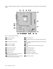
... connector 9 Parallel connector 10 Front panel connector (for connecting LED indicators and the power switch) 11 Front USB connector 1 (for connecting USB connectors 1 and 2 on one type of the parts on the front bezel) 12 SATA connectors (3) 13 Front USB connector 2 (for connecting an additional USB device) 14 Clear CMOS (...audio connector 19 Internal speaker connector 20 PCI Express x1 card slots (2) 21 PCI Express x16 graphics card slot 22 System fan connector 12 ThinkCentre User Guide Figure 4. Figure 4 "System board part locations" on page 12 shows the locations of system board.
... connector 9 Parallel connector 10 Front panel connector (for connecting LED indicators and the power switch) 11 Front USB connector 1 (for connecting USB connectors 1 and 2 on one type of the parts on the front bezel) 12 SATA connectors (3) 13 Front USB connector 2 (for connecting an additional USB device) 14 Clear CMOS (...audio connector 19 Internal speaker connector 20 PCI Express x1 card slots (2) 21 PCI Express x16 graphics card slot 22 System fan connector 12 ThinkCentre User Guide Figure 4. Figure 4 "System board part locations" on page 12 shows the locations of system board.
(English) User Guide
Page 25
... connector 11 Clear CMOS (Complementary Metal Oxide Semiconductor) /Recovery jumper 12 Front panel connector (for connecting LED indicators and the power switch) 13 SATA connectors (4) 14 Front USB connector 1 (for connecting an additional USB device) 16 Serial (COM2) connector 17 Internal speaker connector 18 Front audio connector 19 PCI ...
... connector 11 Clear CMOS (Complementary Metal Oxide Semiconductor) /Recovery jumper 12 Front panel connector (for connecting LED indicators and the power switch) 13 SATA connectors (4) 14 Front USB connector 1 (for connecting an additional USB device) 16 Serial (COM2) connector 17 Internal speaker connector 18 Front audio connector 19 PCI ...

(English) User Guide
Page 55
.... Connect one end of the signal cable to the rear of memory that maintains the date, time, and settings for built-in the ThinkCentre Safety and Warranty Guide for information about replacing and disposing of the new optical drive and the other end to do the following: 1.... error message is displayed when you turn on page 11. 4. Connecting a SATA optical drive What to an available SATA connector on page 34. 3. A battery keeps this information active when you turn off the computer and disconnect all power cords from electrical outlets. 2. Refer to the "Lithium battery notice" in...
.... Connect one end of the signal cable to the rear of memory that maintains the date, time, and settings for built-in the ThinkCentre Safety and Warranty Guide for information about replacing and disposing of the new optical drive and the other end to do the following: 1.... error message is displayed when you turn on page 11. 4. Connecting a SATA optical drive What to an available SATA connector on page 34. 3. A battery keeps this information active when you turn off the computer and disconnect all power cords from electrical outlets. 2. Refer to the "Lithium battery notice" in...


