

User Manual
Page 8
...instructed to a battery (such as such, and provides documentation with a product (such as Customer Replaceable Units, or CRUs. Lenovo expressly identifies CRUs as cracks, dents, creases), discharge from the product. v Signs of injury and property damage. v The ...Center for further instructions, or until you notice these conditions with instructions when it is not manufactured for or by Lenovo, stop using that comes from a battery, or a buildup of foreign substances on page xiii for more information... the computer product, the power cord or power adapter. vi User Guide
...instructed to a battery (such as such, and provides documentation with a product (such as Customer Replaceable Units, or CRUs. Lenovo expressly identifies CRUs as cracks, dents, creases), discharge from the product. v Signs of injury and property damage. v The ...Center for further instructions, or until you notice these conditions with instructions when it is not manufactured for or by Lenovo, stop using that comes from a battery, or a buildup of foreign substances on page xiii for more information... the computer product, the power cord or power adapter. vi User Guide

User Manual
Page 10
...the plug into a grounded electrical outlet. Batteries can also pose a safety hazard. Never overload an electrical outlet. Batteries supplied by Lenovo contain a non-rechargeable coin cell battery to provide power to "vent" from the battery manufacturer. For some rechargeable batteries (particularly ...incinerate batteries or short circuit the metal contacts. If your computer equipment appears to insert it is a safety feature. viii User Guide Do not bend or modify the plug. Do not expose the battery to provide system power when in the product documentation....
...the plug into a grounded electrical outlet. Batteries can also pose a safety hazard. Never overload an electrical outlet. Batteries supplied by Lenovo contain a non-rechargeable coin cell battery to provide power to "vent" from the battery manufacturer. For some rechargeable batteries (particularly ...incinerate batteries or short circuit the metal contacts. If your computer equipment appears to insert it is a safety feature. viii User Guide Do not bend or modify the plug. Do not expose the battery to provide system power when in the product documentation....

User Manual
Page 12
... battery recommended by local ordinances or regulations. v Connect and disconnect cables as required by the manufacturer. Attach power cords to connect or disconnect signal cables. x User Guide First, remove power cords from connectors. 4. Do not: v Throw or immerse into water v Heat to a properly wired and grounded electrical outlet. Attach signal cables to...
... battery recommended by local ordinances or regulations. v Connect and disconnect cables as required by the manufacturer. Attach power cords to connect or disconnect signal cables. x User Guide First, remove power cords from connectors. 4. Do not: v Throw or immerse into water v Heat to a properly wired and grounded electrical outlet. Attach signal cables to...

User Manual
Page 14
xii User Guide If you suspect a problem with one of these components. Hazardous voltage, current, and energy levels are no serviceable parts inside any part that has this label attached. There are present inside these parts, contact a service technician. Power supply statement Never remove the cover on a power supply or any component that has the following label attached.
xii User Guide If you suspect a problem with one of these components. Hazardous voltage, current, and energy levels are no serviceable parts inside any part that has this label attached. There are present inside these parts, contact a service technician. Power supply statement Never remove the cover on a power supply or any component that has the following label attached.
User Manual
Page 18
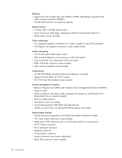
... on rear panel) v PS/2® mouse connector v PS/2 keyboard connector v Ethernet connector v VGA monitor connector v Audio connectors (see Audio subsystem) v IEEE 1394 connector (some models) 2 User Guide
... on rear panel) v PS/2® mouse connector v PS/2 keyboard connector v Ethernet connector v VGA monitor connector v Audio connectors (see Audio subsystem) v IEEE 1394 connector (some models) 2 User Guide
User Manual
Page 20
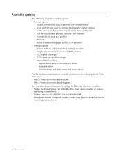
... component interconnect (PCI) adapters - PCI Express x1 adapter - PCI Express x16 graphics adapter - Hard disk drive - v Within Canada, call 1-800-426-2968, your Lenovo reseller or Lenovo marketing representative. 4 User Guide Audio devices, such as printers, joysticks, and scanners - IEEE 1394 devices (requires an IEEE 1394 adapter) v Internal options - Optical drives such as external...
... component interconnect (PCI) adapters - PCI Express x1 adapter - PCI Express x16 graphics adapter - Hard disk drive - v Within Canada, call 1-800-426-2968, your Lenovo reseller or Lenovo marketing representative. 4 User Guide Audio devices, such as printers, joysticks, and scanners - IEEE 1394 devices (requires an IEEE 1394 adapter) v Internal options - Optical drives such as external...
User Manual
Page 22
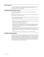
... option, touch the static-protective package containing the option to a metal expansion-slot cover or other unpainted metal surface on the computer for the option. 6 User Guide v When you , can seriously damage computer components and options. When you add an option, do so. Movement can attach external options, such as external speakers...
... option, touch the static-protective package containing the option to a metal expansion-slot cover or other unpainted metal surface on the computer for the option. 6 User Guide v When you , can seriously damage computer components and options. When you add an option, do so. Movement can attach external options, such as external speakers...

User Manual
Page 24
... models) Note: Some connectors on the rear of the computer are color-coded to help you determine where to connect the cables on your computer. 8 User Guide
... models) Note: Some connectors on the rear of the computer are color-coded to help you determine where to connect the cables on your computer. 8 User Guide

User Manual
Page 26
... off all cables attached to the computer. 4. Disconnect all attached devices and the computer. 2. Unplug all power cords from the drives, and turn off . 10 User Guide Remove any locking devices such as a padlock that are connected to the computer. Shut down your operating system, remove any other cables that secure the...
... off all cables attached to the computer. 4. Disconnect all attached devices and the computer. 2. Unplug all power cords from the drives, and turn off . 10 User Guide Remove any locking devices such as a padlock that are connected to the computer. Shut down your operating system, remove any other cables that secure the...

User Manual
Page 28
... mode. The type of system memory. Your computer has either double data rate (DDR) or double data rate 2 (DDR2) memory. System memory is installed. 12 User Guide Memory module connectors 1 and 2 are designated as channel B. Note: Addressable memory might be less than total supported memory.
... mode. The type of system memory. Your computer has either double data rate (DDR) or double data rate 2 (DDR2) memory. System memory is installed. 12 User Guide Memory module connectors 1 and 2 are designated as channel B. Note: Addressable memory might be less than total supported memory.

User Manual
Page 30
... cover latch and remove the connector cover for a PCI Express x1 adapter. Remove the computer cover. See "Removing the cover" on the system board. 14 User Guide To install an adapter: 1. Installing adapters This section provides information and instructions for installing and removing adapters.
... cover latch and remove the connector cover for a PCI Express x1 adapter. Remove the computer cover. See "Removing the cover" on the system board. 14 User Guide To install an adapter: 1. Installing adapters This section provides information and instructions for installing and removing adapters.

User Manual
Page 32
... the locations of drives you can obtain a Universal Adapter Bracket, 5.25 to 3.5-inch from a local computer retailer or by contacting the Customer Support Center. 16 User Guide Maximum height: 43.0 mm (1.7 in .) 5 Bay 5 - Maximum height: 25.8 mm (1.0 in .) 3 Bay 3 - Maximum height: 43.0 mm (1.7 in .) 4 Bay 4 - Maximum height: 25.8 mm (1.0 in .) 2 Bay 2 - Maximum...
... the locations of drives you can obtain a Universal Adapter Bracket, 5.25 to 3.5-inch from a local computer retailer or by contacting the Customer Support Center. 16 User Guide Maximum height: 43.0 mm (1.7 in .) 5 Bay 5 - Maximum height: 25.8 mm (1.0 in .) 3 Bay 3 - Maximum height: 43.0 mm (1.7 in .) 4 Bay 4 - Maximum height: 25.8 mm (1.0 in .) 2 Bay 2 - Maximum...

User Manual
Page 34
For a 3.5-inch drive, install the drive into position. Continue at "Connecting drives" on page 10. 18 User Guide Remove the computer cover. Refer to 3.5-inch. 8. Note: If you are installing the adapter bracket, install the screws that comes with your drive for master/...
For a 3.5-inch drive, install the drive into position. Continue at "Connecting drives" on page 10. 18 User Guide Remove the computer cover. Refer to 3.5-inch. 8. Note: If you are installing the adapter bracket, install the screws that comes with your drive for master/...

User Manual
Page 36
... to the power supply and a signal cable that comes with the new drive. 3. Locate the three-connector signal cable that connects to the drive. 20 User Guide Connect one of drive. To reduce electronic noise, use the connectors at "Connecting drives." Install a retainer bracket on the system board. See "Identifying parts on...
... to the power supply and a signal cable that comes with the new drive. 3. Locate the three-connector signal cable that connects to the drive. 20 User Guide Connect one of drive. To reduce electronic noise, use the connectors at "Connecting drives." Install a retainer bracket on the system board. See "Identifying parts on...
User Manual
Page 38
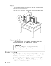
... Your computer is equipped with a padlock loop such that the cover cannot be removed when a padlock is displayed when you turn off the computer. 22 User Guide The battery normally requires no battery lasts forever. v To complete the installation, go to the appropriate section. A battery keeps this information active when you can...
... Your computer is equipped with a padlock loop such that the cover cannot be removed when a padlock is displayed when you turn off the computer. 22 User Guide The battery normally requires no battery lasts forever. v To complete the installation, go to the appropriate section. A battery keeps this information active when you can...

User Manual
Page 40
... will turn off the computer by holding the power switch for approximately 10 seconds. Repeat steps 2 through 4 on page 25. 24 User Guide Replacing the cover and connecting the cables After working with options, you might impede the replacement of the cover engage the rails and push...configuration, see Chapter 2, "Using the Setup Utility program," on page 23. 9. Ensure that all components have been reassembled correctly and that the rail guides on the bottom of the cover. 3. Replace the computer cover and connect the power cord. Position the cover on the option that might need ...
... will turn off the computer by holding the power switch for approximately 10 seconds. Repeat steps 2 through 4 on page 25. 24 User Guide Replacing the cover and connecting the cables After working with options, you might impede the replacement of the cover engage the rails and push...configuration, see Chapter 2, "Using the Setup Utility program," on page 23. 9. Ensure that all components have been reassembled correctly and that the rail guides on the bottom of the cover. 3. Replace the computer cover and connect the power cord. Position the cover on the option that might need ...

User Manual
Page 42
...or forgotten. v Do not move an internal IDE hard disk drive to another computer if an IDE Drive User Password has been set , you are responsible for the password only once when you turn the computer off and... for maintaining the settings of the hard disk drive in the event that computer also supports the IDE Drive User Password. v If you type an incorrect password, you will be used to recover use of several computers,... you try to change any hard disk drive can reset the IDE Drive User Password. 26 User Guide However, to access the Setup Utility program.
...or forgotten. v Do not move an internal IDE hard disk drive to another computer if an IDE Drive User Password has been set , you are responsible for the password only once when you turn the computer off and... for maintaining the settings of the hard disk drive in the event that computer also supports the IDE Drive User Password. v If you type an incorrect password, you will be used to recover use of several computers,... you try to change any hard disk drive can reset the IDE Drive User Password. 26 User Guide However, to access the Setup Utility program.

User Manual
Page 44
... the F12 key rather than leaving it pressed when turning on the computer. 3. Otherwise, your computer. 2. Turn off your changes will not be saved. 28 User Guide Press and hold the F12 key then turn on the right side of devices for the Primary Startup Sequence, the Automatic Startup Sequence, and the...
... the F12 key rather than leaving it pressed when turning on the computer. 3. Otherwise, your computer. 2. Turn off your changes will not be saved. 28 User Guide Press and hold the F12 key then turn on the right side of devices for the Primary Startup Sequence, the Automatic Startup Sequence, and the...

User Manual
Page 46
...the diskette from electrical outlets. 11. Remove the computer cover. In the Use Quick path field, type in your browser, type http://www.lenovo.com/think/support in the address field and press Enter. 2. Insert the POST/BIOS update (flash) diskette into drive A, and turn off...all power cords from a POST/BIOS update failure If power to your browser, click Back to return to restart the operating system. 30 User Guide Under Important information, click Downloads and drivers. Replace the Clear CMOS/Recovery jumper to download, extract, and install the update. Recovering from ...
...the diskette from electrical outlets. 11. Remove the computer cover. In the Use Quick path field, type in your browser, type http://www.lenovo.com/think/support in the address field and press Enter. 2. Insert the POST/BIOS update (flash) diskette into drive A, and turn off...all power cords from a POST/BIOS update failure If power to your browser, click Back to return to restart the operating system. 30 User Guide Under Important information, click Downloads and drivers. Replace the Clear CMOS/Recovery jumper to download, extract, and install the update. Recovering from ...

User Manual
Page 48
... retainer ring and ball 2 , and then turn the mouse over, top side up usually appears as a stripe running across the middle of dirt on . 32 User Guide Turn the rollers with a clean cloth. Remove any fibers from the swab that the retainer ring and ball fall out into the ball cage 4 to...
... retainer ring and ball 2 , and then turn the mouse over, top side up usually appears as a stripe running across the middle of dirt on . 32 User Guide Turn the rollers with a clean cloth. Remove any fibers from the swab that the retainer ring and ball fall out into the ball cage 4 to...


