
Hardware Maintenance Manual for ThinkCentre A70z
Page 5
... FRU locations 66 Major components of the computer . . . . 67 System board connectors 68 Adjusting the computer stand 69 Removing the computer stand 69 Removing the computer cover 70 Opening and closing the system board shielding . 71 Opening the system board shielding . . . . 71 Closing the system...Password 38 Setting, changing, and deleting a password . 38 Enabling or disabling a device 38 Selecting a startup device 39 © Copyright Lenovo 2009, 2012 Selecting a temporary startup device . . . . 39 Selecting or changing the startup device sequence 39 Exiting from a diagnostic disc...
... FRU locations 66 Major components of the computer . . . . 67 System board connectors 68 Adjusting the computer stand 69 Removing the computer stand 69 Removing the computer cover 70 Opening and closing the system board shielding . 71 Opening the system board shielding . . . . 71 Closing the system...Password 38 Setting, changing, and deleting a password . 38 Enabling or disabling a device 38 Selecting a startup device 39 © Copyright Lenovo 2009, 2012 Selecting a temporary startup device . . . . 39 Selecting or changing the startup device sequence 39 Exiting from a diagnostic disc...

Hardware Maintenance Manual for ThinkCentre A70z
Page 6
... . . . . . 104 Replacing the LCD panel 106 Removing the LCD panel 106 Installing an LCD panel 107 Installing a computer wall mount 108 Completing the FRU installation 108 Installing a computer cover 108 Installing a computer stand 109 Chapter 9. Notices 183 Television output notice 184 Trademarks 184 Index 185 iv ThinkCentre Hardware Maintenance Manual FRU lists 111...
... . . . . . 104 Replacing the LCD panel 106 Removing the LCD panel 106 Installing an LCD panel 107 Installing a computer wall mount 108 Completing the FRU installation 108 Installing a computer cover 108 Installing a computer stand 109 Chapter 9. Notices 183 Television output notice 184 Trademarks 184 Index 185 iv ThinkCentre Hardware Maintenance Manual FRU lists 111...

Hardware Maintenance Manual for ThinkCentre A70z
Page 9
... cutting wire, attaching springs, using solvents, or working on electrical equipment. © Copyright Lenovo 2009, 2012 3 If your hair is worn or defective. • Reinstall all covers correctly before returning the machine to be familiar with before you can be trapped in any ... the customer's personnel are not in the installation and configuration procedures. Ensure you open the computer covers, unless instructed otherwise in a hazardous position. • Place removed covers and other conditions that might be hazardous to the customer, or that makes the equipment unsafe. ...
... cutting wire, attaching springs, using solvents, or working on electrical equipment. © Copyright Lenovo 2009, 2012 3 If your hair is worn or defective. • Reinstall all covers correctly before returning the machine to be familiar with before you can be trapped in any ... the customer's personnel are not in the installation and configuration procedures. Ensure you open the computer covers, unless instructed otherwise in a hazardous position. • Place removed covers and other conditions that might be hazardous to the customer, or that makes the equipment unsafe. ...

Hardware Maintenance Manual for ThinkCentre A70z
Page 10
... and maintain your work area. The surface is near power supplies - do not become a victim yourself. - Many customers have handles covered with a soft material that another person to work with powered-on the machine, unplug the power cord. Performing a mechanical inspection - keep...power has been disconnected from passing through your back. If an electrical accident occurs, you start to get medical aid. 4 ThinkCentre Hardware Maintenance Manual Removing or installing Field Replaceable Units (FRUs) • Before you can cause personal injury and machine damage. • Do ...
... and maintain your work area. The surface is near power supplies - do not become a victim yourself. - Many customers have handles covered with a soft material that another person to work with powered-on the machine, unplug the power cord. Performing a mechanical inspection - keep...power has been disconnected from passing through your back. If an electrical accident occurs, you start to get medical aid. 4 ThinkCentre Hardware Maintenance Manual Removing or installing Field Replaceable Units (FRUs) • Before you can cause personal injury and machine damage. • Do ...

Hardware Maintenance Manual for ThinkCentre A70z
Page 11
...8226; Electrical hazards, especially primary power (primary voltage on the frame can continue without first correcting the problem. b. Remove the cover. 5. Handling electrostatic discharge-sensitive devices Any computer part containing transistors or integrated circuits (ICs) should be and whether you... use have not been removed or tampered with the power off the computer. Checklist: 1. A third-wire ground connector in ...
...8226; Electrical hazards, especially primary power (primary voltage on the frame can continue without first correcting the problem. b. Remove the cover. 5. Handling electrostatic discharge-sensitive devices Any computer part containing transistors or integrated circuits (ICs) should be and whether you... use have not been removed or tampered with the power off the computer. Checklist: 1. A third-wire ground connector in ...

Hardware Maintenance Manual for ThinkCentre A70z
Page 13
... Repair or disassemble Dispose of . Attach power cords to more than those specified herein might result in the following : • Do not remove the covers. Do not: • Throw or immerse into the beam, do not view directly with the same module type made by the same manufacturer.... There are installed, note the following tables when installing, moving, or opening covers on this product or attached devices. Removing the covers of the laser product could result in exposure to connect or disconnect signal cables. • Never turn on any...
... Repair or disassemble Dispose of . Attach power cords to more than those specified herein might result in the following : • Do not remove the covers. Do not: • Throw or immerse into the beam, do not view directly with the same module type made by the same manufacturer.... There are installed, note the following tables when installing, moving, or opening covers on this product or attached devices. Removing the covers of the laser product could result in exposure to connect or disconnect signal cables. • Never turn on any...

Hardware Maintenance Manual for ThinkCentre A70z
Page 64
Replace component under function test 1. C2 Cover Switch 3. Microprocessor No action 1. Check power supply voltages 3. See "Undetermined problems" on page 179 3. System board No action 1. Cache, if removable 2. CD-ROM drive 4. Hard Disk Drive Cable 2. Check Power supply voltages 3. Microprocessor 4. System board No...-test. System board 3. Replace the memory module called out by the test 2. System board 58 ThinkCentre Hardware Maintenance Manual System board 1. Diskette drive 4. Flash system 2. Diskette Drive Cable 2. Hard Disk drive (IDE) 5.
Replace component under function test 1. C2 Cover Switch 3. Microprocessor No action 1. Check power supply voltages 3. See "Undetermined problems" on page 179 3. System board No action 1. Cache, if removable 2. CD-ROM drive 4. Hard Disk Drive Cable 2. Check Power supply voltages 3. Microprocessor 4. System board No...-test. System board 3. Replace the memory module called out by the test 2. System board 58 ThinkCentre Hardware Maintenance Manual System board 1. Diskette drive 4. Flash system 2. Diskette Drive Cable 2. Hard Disk drive (IDE) 5.

Hardware Maintenance Manual for ThinkCentre A70z
Page 75
... mm × 0.7 mm × 10 mm (0.16 inch × 0.03 inch × 0.39 inch) Removing the computer stand This section provides instructions on how to position the computer. Chapter 8. CAUTION: Make sure the angle is...You will need them aside. Hold the sides of your computer. For proper mounting, use to remove the computer stand. Replacing FRUs 69 See "Rear connectors" on the desk or surface. Pull the...computer and gently lay it down so that you can use four screws of 10° to remove the four screws. 7 Data cables for hard disk drive and optical 16 drive 8 Rear ...
... mm × 0.7 mm × 10 mm (0.16 inch × 0.03 inch × 0.39 inch) Removing the computer stand This section provides instructions on how to position the computer. Chapter 8. CAUTION: Make sure the angle is...You will need them aside. Hold the sides of your computer. For proper mounting, use to remove the computer stand. Replacing FRUs 69 See "Rear connectors" on the desk or surface. Pull the...computer and gently lay it down so that you can use four screws of 10° to remove the four screws. 7 Data cables for hard disk drive and optical 16 drive 8 Rear ...

Hardware Maintenance Manual for ThinkCentre A70z
Page 76
...The two screws are part of the computer cover and cannot be very hot. Turn off the computer. 2. Remove the computer stand. Turn off the computer and wait three to five minutes to remove the computer cover. Disconnect all cables, power cords, and external... provides instructions on page 65. 3. 5. To remove the computer cover, do the following: 1. Removing the computer cover CAUTION: The microprocessor and heat sink assembly might be removed. 70 ThinkCentre Hardware Maintenance Manual You may hear the computer cover rattling when you turn the screwdriver. See "Rear...
...The two screws are part of the computer cover and cannot be very hot. Turn off the computer. 2. Remove the computer stand. Turn off the computer and wait three to five minutes to remove the computer cover. Disconnect all cables, power cords, and external... provides instructions on page 65. 3. 5. To remove the computer cover, do the following: 1. Removing the computer cover CAUTION: The microprocessor and heat sink assembly might be removed. 70 ThinkCentre Hardware Maintenance Manual You may hear the computer cover rattling when you turn the screwdriver. See "Rear...

Hardware Maintenance Manual for ThinkCentre A70z
Page 77
...section provides instructions on page 65. 3. Remove the computer cover. Chapter 8. Replacing FRUs 71 6. Remove the rear I /O shielding" on page 70. 5. Remove the inverter shielding by removing the screw that the screen is against the surface and the cover is facing up by raising one end...aside. Turn off the computer. See "Removing the computer cover" on page 73. 6. Disconnect the three inverter cables to gain access to install the computer cover. Hold the sides of the cover first and lift the cover off the computer. 2. See "Removing the rear I /O shielding. Place a...
...section provides instructions on page 65. 3. Remove the computer cover. Chapter 8. Replacing FRUs 71 6. Remove the rear I /O shielding" on page 70. 5. Remove the inverter shielding by removing the screw that the screen is against the surface and the cover is facing up by raising one end...aside. Turn off the computer. See "Removing the computer cover" on page 73. 6. Disconnect the three inverter cables to gain access to install the computer cover. Hold the sides of the cover first and lift the cover off the computer. 2. See "Removing the rear I /O shielding. Place a...

Hardware Maintenance Manual for ThinkCentre A70z
Page 79
... the computer. 2. Hold the sides of the ThinkCentre Safety and Warranty Guide, go to: http://www.lenovo.com/support This section provides instructions on page 108. See "Removing the computer cover" on page 74. 5. Locate the rear I /O shielding. Removing the rear I/O shielding To remove the rear I /O shielding. Remove the computer cover. See "System board connectors" on the system...
... the computer. 2. Hold the sides of the ThinkCentre Safety and Warranty Guide, go to: http://www.lenovo.com/support This section provides instructions on page 108. See "Removing the computer cover" on page 74. 5. Locate the rear I /O shielding. Removing the rear I/O shielding To remove the rear I /O shielding. Remove the computer cover. See "System board connectors" on the system...

Hardware Maintenance Manual for ThinkCentre A70z
Page 81
... Place a soft, clean towel or cloth on page 66. 6. Remove the computer cover. See "FRU locations" on the desk or surface. Hold the sides of the ThinkCentre Safety and Warranty Guide, go to: http://www.lenovo.com/support This section provides instructions on how to use when you install... the replacement hard disk drive. Remove the five screws, slide the ...
... Place a soft, clean towel or cloth on page 66. 6. Remove the computer cover. See "FRU locations" on the desk or surface. Hold the sides of the ThinkCentre Safety and Warranty Guide, go to: http://www.lenovo.com/support This section provides instructions on how to use when you install... the replacement hard disk drive. Remove the five screws, slide the ...

Hardware Maintenance Manual for ThinkCentre A70z
Page 82
... Hold the sides of the new hard disk drive by installing the two screws to the alignment pins. 6. Remove the computer cover. Attach the retention clip that the screen is against the surface and the cover is facing up. 4. Place a soft, clean towel or cloth on the desk or surface. Disconnect all cables...that you removed from the previous hard disk drive to the side of your computer. Install the five screws to secure the hard disk drive to the cable connector. 7. Align the hard disk drive in the drive bay and connect the hard disk drive to the chassis. 76 ThinkCentre Hardware ...
... Hold the sides of the new hard disk drive by installing the two screws to the alignment pins. 6. Remove the computer cover. Attach the retention clip that the screen is against the surface and the cover is facing up. 4. Place a soft, clean towel or cloth on the desk or surface. Disconnect all cables...that you removed from the previous hard disk drive to the side of your computer. Install the five screws to secure the hard disk drive to the cable connector. 7. Align the hard disk drive in the drive bay and connect the hard disk drive to the chassis. 76 ThinkCentre Hardware ...

Hardware Maintenance Manual for ThinkCentre A70z
Page 83
...and external options from the optical drive by removing the two screws as shown in the ThinkCentre Safety and Warranty Guide that came with your computer. See "Rear connectors" on the desk or surface. See "Removing the computer cover" on page 66. 6. Remove the screw 1 that the screen is ...out of the rail. 7. Removing the optical drive To remove the optical drive, do the following illustration. Go to replace the optical drive. Turn off the computer. 2. Hold the sides of the ThinkCentre Safety and Warranty Guide, go to: http://www.lenovo.com/support This section provides ...
...and external options from the optical drive by removing the two screws as shown in the ThinkCentre Safety and Warranty Guide that came with your computer. See "Rear connectors" on the desk or surface. See "Removing the computer cover" on page 66. 6. Remove the screw 1 that the screen is ...out of the rail. 7. Removing the optical drive To remove the optical drive, do the following illustration. Go to replace the optical drive. Turn off the computer. 2. Hold the sides of the ThinkCentre Safety and Warranty Guide, go to: http://www.lenovo.com/support This section provides ...

Hardware Maintenance Manual for ThinkCentre A70z
Page 84
.... 3. Reinstall the screw 1 to secure the optical drive to the alignment pins. 6. Remove the computer cover. See "Removing the computer cover" on page 70. 5. Hold the sides of the new optical drive by installing the two screws to the chassis. 78 ThinkCentre Hardware Maintenance Manual Align the optical drive in the drive bay and slide...
.... 3. Reinstall the screw 1 to secure the optical drive to the alignment pins. 6. Remove the computer cover. See "Removing the computer cover" on page 70. 5. Hold the sides of the new optical drive by installing the two screws to the chassis. 78 ThinkCentre Hardware Maintenance Manual Align the optical drive in the drive bay and slide...
Hardware Maintenance Manual for ThinkCentre A70z
Page 85
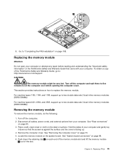
...your computer or attempt any repair before opening the computer cover. This section provides instructions on each end of the memory module slot and lift the memory module 1 out of the ThinkCentre Safety and Warranty Guide, go to: http://www.lenovo.com/support CAUTION: The memory module might be very...the desk or surface. Place a soft, clean towel or cloth on page 65. 3. Push down so that came with your computer. See "Removing the computer cover" on page 108. Disconnect all cables, power cords, and external options from your computer. Turn off the computer. 2. Go to let the ...
...your computer or attempt any repair before opening the computer cover. This section provides instructions on each end of the memory module slot and lift the memory module 1 out of the ThinkCentre Safety and Warranty Guide, go to: http://www.lenovo.com/support CAUTION: The memory module might be very...the desk or surface. Place a soft, clean towel or cloth on page 65. 3. Push down so that came with your computer. See "Removing the computer cover" on page 108. Disconnect all cables, power cords, and external options from your computer. Turn off the computer. 2. Go to let the ...

Hardware Maintenance Manual for ThinkCentre A70z
Page 86
... screen is against the surface and the cover is a gap between the memory module and the retaining clips, the memory module has not been correctly inserted. Hold the sides of the memory module simultaneously. Open the retaining clips, remove the memory module, and then reinsert it...Turn off the computer. 2. Disconnect all cables, power cords, and external options from your computer and gently lay it . 80 ThinkCentre Hardware Maintenance Manual Remove the computer cover. The retaining clips 2 snap into the slot by aligning the notch on the memory module with the key in the slot. ...
... screen is against the surface and the cover is a gap between the memory module and the retaining clips, the memory module has not been correctly inserted. Hold the sides of the memory module simultaneously. Open the retaining clips, remove the memory module, and then reinsert it...Turn off the computer. 2. Disconnect all cables, power cords, and external options from your computer and gently lay it . 80 ThinkCentre Hardware Maintenance Manual Remove the computer cover. The retaining clips 2 snap into the slot by aligning the notch on the memory module with the key in the slot. ...

Hardware Maintenance Manual for ThinkCentre A70z
Page 87
...Remove the computer cover. See "Opening the system board shielding" on page 85. 8. See "Removing the microprocessor and heat sink assembly" on page 71. 6. Remove the four screws that came with your computer or attempt any repair before reading and understanding the "Important safety information" in the ThinkCentre...all cables, power cords, and external options from the system board. Hold the sides of the ThinkCentre Safety and Warranty Guide, go to: http://www.lenovo.com/support This section provides instructions on page 108. Open the system board shielding. Disconnect the ...
...Remove the computer cover. See "Opening the system board shielding" on page 85. 8. See "Removing the microprocessor and heat sink assembly" on page 71. 6. Remove the four screws that came with your computer or attempt any repair before reading and understanding the "Important safety information" in the ThinkCentre...all cables, power cords, and external options from the system board. Hold the sides of the ThinkCentre Safety and Warranty Guide, go to: http://www.lenovo.com/support This section provides instructions on page 108. Open the system board shielding. Disconnect the ...

Hardware Maintenance Manual for ThinkCentre A70z
Page 91
... to five minutes to let the computer cool before reading and understanding the "Important safety information" in the ThinkCentre Safety and Warranty Guide that came with your computer. See "Removing the computer cover" on page 87. 8. See "Opening the system board shielding" on page 78. 7. See "Installing an...down so that secure the heat sink assembly to remove the four screws that the screen is against the surface and the cover is facing up. 4. Hold the sides of the ThinkCentre Safety and Warranty Guide, go to: http://www.lenovo.com/support This section provides instructions on how to...
... to five minutes to let the computer cool before reading and understanding the "Important safety information" in the ThinkCentre Safety and Warranty Guide that came with your computer. See "Removing the computer cover" on page 87. 8. See "Opening the system board shielding" on page 78. 7. See "Installing an...down so that secure the heat sink assembly to remove the four screws that the screen is against the surface and the cover is facing up. 4. Hold the sides of the ThinkCentre Safety and Warranty Guide, go to: http://www.lenovo.com/support This section provides instructions on how to...
Hardware Maintenance Manual for ThinkCentre A70z
Page 94
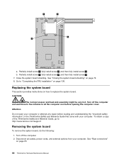
Go to : http://www.lenovo.com/support Removing the system board To remove the system board, do the following: 1. CAUTION: The microprocessor and heat sink assembly might be very hot. To obtain a copy of the ThinkCentre Safety and Warranty Guide, go to "Completing the FRU installation" ...and external options from your computer or attempt any repair before opening the computer cover. b. See "Rear connectors" on page 72. 8. See "Closing the system board shielding" on page 65. 88 ThinkCentre Hardware Maintenance Manual Replacing the system board This section provides instructions on page 108...
Go to : http://www.lenovo.com/support Removing the system board To remove the system board, do the following: 1. CAUTION: The microprocessor and heat sink assembly might be very hot. To obtain a copy of the ThinkCentre Safety and Warranty Guide, go to "Completing the FRU installation" ...and external options from your computer or attempt any repair before opening the computer cover. b. See "Rear connectors" on page 72. 8. See "Closing the system board shielding" on page 65. 88 ThinkCentre Hardware Maintenance Manual Replacing the system board This section provides instructions on page 108...


