User Manual
Page 5
... down the computer 11 Chapter 3. Arranging your computer 4 Turning on the system board . . . . . 25 Installing memory 29 Installing PCI adapters 30 Installing internal drives 31 Drive specifications 32 Installing a drive in bay 1 33 Installing a diskette ... startup device sequence . . . . 51 Advanced settings 52 Exiting from a diskette . . . . 53 Chapter 7. Troubleshooting and diagnostics 55 © Lenovo 2006, 2007. Installing options . . . . . 13 Features 13 Available options 16 Specifications 17 Supported operating positions 18 Tools required 18 Handling static-sensitive...
... down the computer 11 Chapter 3. Arranging your computer 4 Turning on the system board . . . . . 25 Installing memory 29 Installing PCI adapters 30 Installing internal drives 31 Drive specifications 32 Installing a drive in bay 1 33 Installing a diskette ... startup device sequence . . . . 51 Advanced settings 52 Exiting from a diskette . . . . 53 Chapter 7. Troubleshooting and diagnostics 55 © Lenovo 2006, 2007. Installing options . . . . . 13 Features 13 Available options 16 Specifications 17 Supported operating positions 18 Tools required 18 Handling static-sensitive...

User Manual
Page 9
... install a static-sensitive option or CRU, touch the static-protective package containing the part to let the computer cool before opening the cover. Handle adapters, memory modules, and other unpainted metal surface on it down. This reduces static electricity in the package and your movement. Power cords and power adapters Use...
... install a static-sensitive option or CRU, touch the static-protective package containing the part to let the computer cool before opening the cover. Handle adapters, memory modules, and other unpainted metal surface on it down. This reduces static electricity in the package and your movement. Power cords and power adapters Use...
User Manual
Page 33
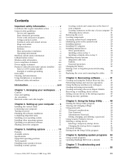
.... System information The following information covers a variety of the computer features and preinstalled software. For information for your computer by Lenovo. Important Before you work safely. These precautions and guidelines will help you install or remove any option, read "Important safety ...expand the capabilities of your computer. Portions © IBM Corp. 2005. 13 Note: Use only the parts provided by adding memory, adapters, or drives. Installing options Features This chapter provides an introduction to the features and options that come with the instructions ...
.... System information The following information covers a variety of the computer features and preinstalled software. For information for your computer by Lenovo. Important Before you work safely. These precautions and guidelines will help you install or remove any option, read "Important safety ...expand the capabilities of your computer. Portions © IBM Corp. 2005. 13 Note: Use only the parts provided by adding memory, adapters, or drives. Installing options Features This chapter provides an introduction to the features and options that come with the instructions ...
User Manual
Page 34
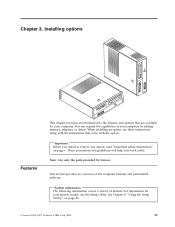
...; 4 processor with HyperThreading Technology v Intel Pentium D processor v Intel Celeron® D processor v Internal cache (size varies by model type) Memory v Support for two double data rate 2 (DDR2) dual inline memory modules (DIMMs) v 4 Mb flash memory for system programs Internal drives v Diskette drive (some models) v Parallel Advanced Technology Attachment (PATA) internal hard disk (some models...
...; 4 processor with HyperThreading Technology v Intel Pentium D processor v Intel Celeron® D processor v Internal cache (size varies by model type) Memory v Support for two double data rate 2 (DDR2) dual inline memory modules (DIMMs) v 4 Mb flash memory for system programs Internal drives v Diskette drive (some models) v Parallel Advanced Technology Attachment (PATA) internal hard disk (some models...

User Manual
Page 36
...) - USB devices, such as external modems and digital cameras - The operating systems listed here are being certified or tested for compatibility1 (varies by Lenovo as printers and external drives - Security devices, such as CD drives and DVD drives (some available options: v External options - Optical drive, such... (PCI) adapters - PCI Express x1 adapter (some models) - Operating systems, certified or tested for compatibility at http://www.lenovo.com/ or contact your computer following are subject to press. System memory, called dual inline memory modules (DIMMs) -
...) - USB devices, such as external modems and digital cameras - The operating systems listed here are being certified or tested for compatibility1 (varies by Lenovo as printers and external drives - Security devices, such as CD drives and DVD drives (some available options: v External options - Optical drive, such... (PCI) adapters - PCI Express x1 adapter (some models) - Operating systems, certified or tested for compatibility at http://www.lenovo.com/ or contact your computer following are subject to press. System memory, called dual inline memory modules (DIMMs) -

User Manual
Page 38
...-sensitive devices Static electricity, although harmless to internal components, you . v Always handle components carefully. v Prevent others from touching components. 18 User Guide Handle adapters and memory modules by the edges. Supported operating positions Attention: Do not block the air vents on the top of the computer with the option. To provide...
...-sensitive devices Static electricity, although harmless to internal components, you . v Always handle components carefully. v Prevent others from touching components. 18 User Guide Handle adapters and memory modules by the edges. Supported operating positions Attention: Do not block the air vents on the top of the computer with the option. To provide...

User Manual
Page 43
Installing options 23 Locating components The following illustration will help you locate the various components in your computer. 1 Optical drive 2 Diskette drive 3 Memory modules 4 Battery 5 Power supply 6 PCI adapter connector 7 PCI Express x16 graphics adapter or PCI Express x1 adapter connector (some models) 8 PCI Express x1 adapter connector or PCI Express x16 graphics adapter (some models) Chapter 3.
Installing options 23 Locating components The following illustration will help you locate the various components in your computer. 1 Optical drive 2 Diskette drive 3 Memory modules 4 Battery 5 Power supply 6 PCI adapter connector 7 PCI Express x16 graphics adapter or PCI Express x1 adapter connector (some models) 8 PCI Express x1 adapter connector or PCI Express x16 graphics adapter (some models) Chapter 3.

User Manual
Page 44
See "Removing the cover" on page 22. 2. Remove the front bezel by releasing the three tabs and pivoting the bezel forward to access system board components such as memory, the battery, and CMOS. Accessing system board components You might have to remove the PCI adapter in order to gain access to the battery. 24 User Guide In some models, you might need to remove the drive bay assembly to remove completely. 3. Remove the computer cover. To access system board components and the drives: 1.
See "Removing the cover" on page 22. 2. Remove the front bezel by releasing the three tabs and pivoting the bezel forward to access system board components such as memory, the battery, and CMOS. Accessing system board components You might have to remove the PCI adapter in order to gain access to the battery. 24 User Guide In some models, you might need to remove the drive bay assembly to remove completely. 3. Remove the computer cover. To access system board components and the drives: 1.

User Manual
Page 46
... on the system board for some computer models. 1 Microprocessor fan connector 12 Front panel connector 2 Microprocessor and heat sink 13 SATA IDE connectors (2) 3 Memory connector 1 14 Front USB connectors (2) 4 Memory connector 2 15 Serial (COM) connector 5 Clear CMOS/Recovery jumper 16 PCI adapter connectors 6 Power connector 17 Front audio connector 7 Diskette drive connector...
... on the system board for some computer models. 1 Microprocessor fan connector 12 Front panel connector 2 Microprocessor and heat sink 13 SATA IDE connectors (2) 3 Memory connector 1 14 Front USB connectors (2) 4 Memory connector 2 15 Serial (COM) connector 5 Clear CMOS/Recovery jumper 16 PCI adapter connectors 6 Power connector 17 Front audio connector 7 Diskette drive connector...

User Manual
Page 47
... the system board for some computer models. 1 Microprocessor and heat sink 12 Front USB connectors (2) 2 Microprocessor fan connector 13 Serial (COM) connector 3 Memory connector 1 14 Front audio connector 4 Memory connector 2 15 CD-IN connector 5 Power connector 16 PCI adapter connectors (2) 6 Diskette drive connector 17 PCI Express x1 adapter connector 7 IDE connector 18...
... the system board for some computer models. 1 Microprocessor and heat sink 12 Front USB connectors (2) 2 Microprocessor fan connector 13 Serial (COM) connector 3 Memory connector 1 14 Front audio connector 4 Memory connector 2 15 CD-IN connector 5 Power connector 16 PCI adapter connectors (2) 6 Diskette drive connector 17 PCI Express x1 adapter connector 7 IDE connector 18...

User Manual
Page 48
The following illustration shows the locations of parts on the system board for some computer models. 1 Microprocessor and heat sink 2 Microprocessor fan connector 3 Memory connector 1 4 Memory connector 2 5 Diskette drive connector 6 Power connector 7 IDE connector 1 8 IDE connector 2 9 Power fan connector 10 SATA IDE connectors (2) 11 Clear CMOS/Recovery jumper 12 Front panel ...
The following illustration shows the locations of parts on the system board for some computer models. 1 Microprocessor and heat sink 2 Microprocessor fan connector 3 Memory connector 1 4 Memory connector 2 5 Diskette drive connector 6 Power connector 7 IDE connector 1 8 IDE connector 2 9 Power fan connector 10 SATA IDE connectors (2) 11 Clear CMOS/Recovery jumper 12 Front panel ...

User Manual
Page 49
... aligns correctly with the connector key 2 on the system board. Remove any combination up to a maximum of system memory. Position the memory module over the memory connector. Chapter 3. See "Accessing system board components" on page 22. 2. Open the retaining clips. 6. See "...Identifying parts on the system board" on page 25. 5. You might prevent access to access the memory connectors. Locate the memory connectors. To install a memory module: 1. When installing memory modules, the following rules apply: v Use 1.8 V, 240-pin, double data rate 2 synchronous dynamic random access...
... aligns correctly with the connector key 2 on the system board. Remove any combination up to a maximum of system memory. Position the memory module over the memory connector. Chapter 3. See "Accessing system board components" on page 22. 2. Open the retaining clips. 6. See "...Identifying parts on the system board" on page 25. 5. You might prevent access to access the memory connectors. Locate the memory connectors. To install a memory module: 1. When installing memory modules, the following rules apply: v Use 1.8 V, 240-pin, double data rate 2 synchronous dynamic random access...

User Manual
Page 57
... the battery fails, the date, time, and configuration information (including passwords) are prompted to type the password to unlock the keyboard for normal use of memory that the cover cannot be removed when a padlock is installed. Refer to "Lithium battery notice" on the computer. Padlock Your computer is equipped with another...
... the battery fails, the date, time, and configuration information (including passwords) are prompted to type the password to unlock the keyboard for normal use of memory that the cover cannot be removed when a padlock is installed. Refer to "Lithium battery notice" on the computer. Padlock Your computer is equipped with another...
User Manual
Page 69
..." for more information. Viewing and changing settings The Setup Utility program menu lists items that cannot be any passwords, read -only memory (EEPROM) of each screen. The keys used to use the keyboard. If your computer, regardless of your computer is not displayed... been set passwords to prevent unauthorized persons from gaining access to twelve characters (a-z and 0-9) and symbols. The following rules: © Lenovo 2006, 2007. When you must use a strong password that identify system configuration topics. However, the operating-system settings might start the ...
..." for more information. Viewing and changing settings The Setup Utility program menu lists items that cannot be any passwords, read -only memory (EEPROM) of each screen. The keys used to use the keyboard. If your computer, regardless of your computer is not displayed... been set passwords to prevent unauthorized persons from gaining access to twelve characters (a-z and 0-9) and symbols. The following rules: © Lenovo 2006, 2007. When you must use a strong password that identify system configuration topics. However, the operating-system settings might start the ...
User Manual
Page 73
... the BIOS from a POST/BIOS update failure. When updates are released, they are available at http://www.lenovo.com. System program updates are available as flash memory). Note: You can understand. Follow the instructions on the World Wide Web. 2. Updating system programs This chapter... contains information about updating POST/BIOS and how to complete the update. © Lenovo 2006, 2007. Using system programs ...
... the BIOS from a POST/BIOS update failure. When updates are released, they are available at http://www.lenovo.com. System program updates are available as flash memory). Note: You can understand. Follow the instructions on the World Wide Web. 2. Updating system programs This chapter... contains information about updating POST/BIOS and how to complete the update. © Lenovo 2006, 2007. Using system programs ...

User Manual
Page 85
... Command Mode. Command A A/ D_ L P T W , @ ! ; Repeat last command executed. Commands can be sent to Command Mode (T.I.E.S. All commands can be typed in the modem non-volatile memory. DS=n E_ E0 E1 +++ H_ H0 Function Manually answer incoming call. Switch from a PC running communication software or any other terminal devices. To make the... echoed Commands are printed in Command Mode until you omit a parameter from a command that requires one of 0. Command) Force modem on-hook (hang up) © Lenovo 2006, 2007. Portions © IBM Corp. 2005. 65
... Command Mode. Command A A/ D_ L P T W , @ ! ; Repeat last command executed. Commands can be sent to Command Mode (T.I.E.S. All commands can be typed in the modem non-volatile memory. DS=n E_ E0 E1 +++ H_ H0 Function Manually answer incoming call. Switch from a PC running communication software or any other terminal devices. To make the... echoed Commands are printed in Command Mode until you omit a parameter from a command that requires one of 0. Command) Force modem on-hook (hang up) © Lenovo 2006, 2007. Portions © IBM Corp. 2005. 65

User Manual
Page 86
... Guide Function Force modem off-hook (make busy) Note: H1 command is not supported for Italy Display product-identification code Factory ROM checksum test Internal memory test Firmware ID Reserved ID Low speaker volume Low speaker volume Medium speaker volume High speaker volume Internal speaker off Internal speaker on until carrier...
... Guide Function Force modem off-hook (make busy) Note: H1 command is not supported for Italy Display product-identification code Factory ROM checksum test Internal memory test Firmware ID Reserved ID Low speaker volume Low speaker volume Medium speaker volume High speaker volume Internal speaker off Internal speaker on until carrier...
User Manual
Page 95
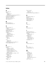
...diagnostic CD image creating 57 running 58 diagnostic diskettes creating 57 running 58 drives bays 32 © Lenovo 2006, 2007. drives (continued) internal 31 specifications 32 dual inline memory modules (DIMMs) 29 E environment, operating 17 Ethernet 14 Ethernet connector 21 exiting, Setup Utility 52... installing operating system 11 software 10 installing options adapters 30 internal drives 31 memory modules 29 security features 35 internal drives 14 K keyboard connector 21 L Lenovo Web site 62 locating components 23 M memory installing 29 modem commands Basic AT 65 Extended AT 67 Fax Class 1 ...
...diagnostic CD image creating 57 running 58 diagnostic diskettes creating 57 running 58 drives bays 32 © Lenovo 2006, 2007. drives (continued) internal 31 specifications 32 dual inline memory modules (DIMMs) 29 E environment, operating 17 Ethernet 14 Ethernet connector 21 exiting, Setup Utility 52... installing operating system 11 software 10 installing options adapters 30 internal drives 31 memory modules 29 security features 35 internal drives 14 K keyboard connector 21 L Lenovo Web site 62 locating components 23 M memory installing 29 modem commands Basic AT 65 Extended AT 67 Fax Class 1 ...
User Manual
Page 96
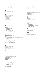
... 49 software installing 10 system board components, accessing 24 connectors 26, 27 identifying parts 25 location 26, 27, 28 76 User Guide system board (continued) memory 16, 29 system management 14 system programs 53 T ThinkVantage Productivity Center 61 trademarks 74 troubleshooting 55 U updating (flashing) BIOS 53 antivirus software 11 operating system...
... 49 software installing 10 system board components, accessing 24 connectors 26, 27 identifying parts 25 location 26, 27, 28 76 User Guide system board (continued) memory 16, 29 system management 14 system programs 53 T ThinkVantage Productivity Center 61 trademarks 74 troubleshooting 55 U updating (flashing) BIOS 53 antivirus software 11 operating system...
(English) Rescue and Recovery 4.3 Deployment Guide
Page 14
...the-minute information on your hard drive. In non-shared memory configurations, 120 MB of free hard disk space. Requirements for non-Lenovo computers Installation on the factory pre-loads for Lenovo computers Lenovo-branded computers must be installed. Installation requirements This section addresses... system requirements for maximum shared memory must meet or exceed the following requirements: Installation requirements: 2.4 GB of non-shared memory is posted on the Lenovo Web page at: http://www.lenovo.com/support/site.wss/document.do?lndocid=MIGR-4Q2QAK...
...the-minute information on your hard drive. In non-shared memory configurations, 120 MB of free hard disk space. Requirements for non-Lenovo computers Installation on the factory pre-loads for Lenovo computers Lenovo-branded computers must be installed. Installation requirements This section addresses... system requirements for maximum shared memory must meet or exceed the following requirements: Installation requirements: 2.4 GB of non-shared memory is posted on the Lenovo Web page at: http://www.lenovo.com/support/site.wss/document.do?lndocid=MIGR-4Q2QAK...


