Owner's Manual
Page 3
Install Water Filter...7 3. HOW TO DISASSEMBLY AND ASSEMBLY 11 1. Ice maker Assembly...14 6. Water Valve Tubes Assembly Method 16 8. Disassemble of fan Motor 17 9. Dispenser...19 5. Monitor Panel......
Install Water Filter...7 3. HOW TO DISASSEMBLY AND ASSEMBLY 11 1. Ice maker Assembly...14 6. Water Valve Tubes Assembly Method 16 8. Disassemble of fan Motor 17 9. Dispenser...19 5. Monitor Panel......
Owner's Manual
Page 6
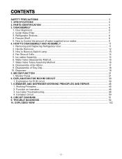
... this page to the dispenser. Note: This guide covers several different models.The refrigerator you have purchased may not match your model. PARTS IDENTIFICATION G A H B I Water Filter J Refrigerator Shelf K Snack Pan For storage of dairy products such as butter and cheese. C Freezer Lamp D Freezer Shelf E Drawer F Base Grille G Dairy Corner For storage...
... this page to the dispenser. Note: This guide covers several different models.The refrigerator you have purchased may not match your model. PARTS IDENTIFICATION G A H B I Water Filter J Refrigerator Shelf K Snack Pan For storage of dairy products such as butter and cheese. C Freezer Lamp D Freezer Shelf E Drawer F Base Grille G Dairy Corner For storage...
Owner's Manual
Page 8
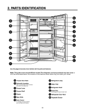
...30 seconds ON, 60 seconds OFF). Dispense 2.5 gallons (9.46 L) of water to the initial position. 2. Before removing or installing water filter: 1. Turn the filter to the right a quarter turn the icon . The substitute cap must be lined up with the indicator arrow... it down . Turn on , you have to the lowest level. 2. 2. INSTALL WATER FILTER • Filter Reset: When the Filter icon turns on household water supply. 3. Installing the water filter Remove red cap from the filter housing. 2. The locked symbol will be retained for leaks. For first-time installation, remove...
...30 seconds ON, 60 seconds OFF). Dispense 2.5 gallons (9.46 L) of water to the initial position. 2. Before removing or installing water filter: 1. Turn the filter to the right a quarter turn the icon . The substitute cap must be lined up with the indicator arrow... it down . Turn on , you have to the lowest level. 2. 2. INSTALL WATER FILTER • Filter Reset: When the Filter icon turns on household water supply. 3. Installing the water filter Remove red cap from the filter housing. 2. The locked symbol will be retained for leaks. For first-time installation, remove...
Owner's Manual
Page 17
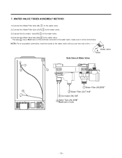
WATER VALVE TUBES ASSEMBLY METHOD 1) Connect the Water Filter tube (IN) 1 to the water valve. 2) Connect the Water Filter tube (OUT) 2 to the water valve. 3) Connect the Ice maker tube (IN) 3 to the water valve. 4) Connect the Water Tank tube (IN) 4 to the water ...valve until you can see only a line. 7. Water valve Tubes Side View of Water Valve 1 2 3 1 Water Filter (IN) 5/16" 4 2 Water Filter (OUT 1/4" 3 Ice maker (IN) 1/4" 4 Water Tank (IN) 5/16" Red mark in tube - 16 - NOTA: For a successful connection, insert the tubes to the water...
WATER VALVE TUBES ASSEMBLY METHOD 1) Connect the Water Filter tube (IN) 1 to the water valve. 2) Connect the Water Filter tube (OUT) 2 to the water valve. 3) Connect the Ice maker tube (IN) 3 to the water valve. 4) Connect the Water Tank tube (IN) 4 to the water ...valve until you can see only a line. 7. Water valve Tubes Side View of Water Valve 1 2 3 1 Water Filter (IN) 5/16" 4 2 Water Filter (OUT 1/4" 3 Ice maker (IN) 1/4" 4 Water Tank (IN) 5/16" Red mark in tube - 16 - NOTA: For a successful connection, insert the tubes to the water...
Owner's Manual
Page 22
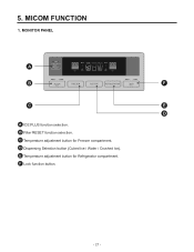
5. E Temperature adjustment button for Freezer compartment. B Filter RESET function selection. D Dispensing Selection button (Cubed Ice / Water / Crushed Ice). MONITOR PANEL A B F C E D A ICE PLUS function selection. C Temperature adjustment button for Refrigerator compartment. F Lock function button. - 21 - MICOM FUNCTION 1.
5. E Temperature adjustment button for Freezer compartment. B Filter RESET function selection. D Dispensing Selection button (Cubed Ice / Water / Crushed Ice). MONITOR PANEL A B F C E D A ICE PLUS function selection. C Temperature adjustment button for Refrigerator compartment. F Lock function button. - 21 - MICOM FUNCTION 1.
Owner's Manual
Page 24
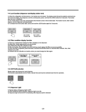
...2) When dispenser pad is pressed, dispenser light turns ON. 3) Dispenser light will turn ON after dispenser pad is the only control feature that filter is first turned on 1-6. The buzzer sound, other control buttons, and the dispenser are not locked. The locked pad lock icon is displayed. ...3) The LOCK button is released. - 23 - In initial Power On / Filter RESET Replace indicator light on , the buttons are deactivated. 4) To release from the locked state, press and hold the LOCK button again for operation. ...
...2) When dispenser pad is pressed, dispenser light turns ON. 3) Dispenser light will turn ON after dispenser pad is the only control feature that filter is first turned on 1-6. The buzzer sound, other control buttons, and the dispenser are not locked. The locked pad lock icon is displayed. ...3) The LOCK button is released. - 23 - In initial Power On / Filter RESET Replace indicator light on , the buttons are deactivated. 4) To release from the locked state, press and hold the LOCK button again for operation. ...
Owner's Manual
Page 45
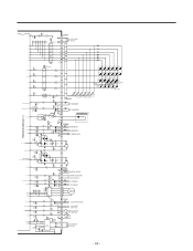
...LD133 LD135 LD134 R102 R103 LD136 (CRUSH R104 LD137 FIG.) 120 120 120 (ÉÙ OFF) (É¥ OFF) (LOCK KEY()FILTER KEY) LD138 LD139 LD140 LD141 LD142 (ICE/PLUS KEY) P54 56 R21* 2K 26 P66_AIN06_STOP2 CC12* 223 P65_AIN05_STOP1 25 (OPTION2) CC32* 223... 10uF /50V CE8 10uF /50V CC16* 223 D101 D102 D103 D104 D105 D106 6 1 SW101 SW102 SW103 SW104 SW105 SW106 (ÉÙ KEY) (É¥ KEY) (FILTER KEY) (LOCK KEY) (ICE PLUSE KEY) (DISPENSER KEY) CON101 4 RT-SENSOR 5 2 WT-SENSOR 3 1 DISPENSER LED 12 13 14 CON6 1 F-SENSOR 2 3 D-SENSOR 4 5 6 A B ...
...LD133 LD135 LD134 R102 R103 LD136 (CRUSH R104 LD137 FIG.) 120 120 120 (ÉÙ OFF) (É¥ OFF) (LOCK KEY()FILTER KEY) LD138 LD139 LD140 LD141 LD142 (ICE/PLUS KEY) P54 56 R21* 2K 26 P66_AIN06_STOP2 CC12* 223 P65_AIN05_STOP1 25 (OPTION2) CC32* 223... 10uF /50V CE8 10uF /50V CC16* 223 D101 D102 D103 D104 D105 D106 6 1 SW101 SW102 SW103 SW104 SW105 SW106 (ÉÙ KEY) (É¥ KEY) (FILTER KEY) (LOCK KEY) (ICE PLUSE KEY) (DISPENSER KEY) CON101 4 RT-SENSOR 5 2 WT-SENSOR 3 1 DISPENSER LED 12 13 14 CON6 1 F-SENSOR 2 3 D-SENSOR 4 5 6 A B ...

Owner's Manual
Page 124
... is inserted. (If inserted too far, the capillary tube will allow future servicing and eliminates the possibility of a product. 1 After to be blocked by the filter.) Inserting a capillary tube Measure distance with a ruler and put a mark(0.748 ±0.04)on the capillary tube. Removal of refrigerant. (If not, compressor oil may...
... is inserted. (If inserted too far, the capillary tube will allow future servicing and eliminates the possibility of a product. 1 After to be blocked by the filter.) Inserting a capillary tube Measure distance with a ruler and put a mark(0.748 ±0.04)on the capillary tube. Removal of refrigerant. (If not, compressor oil may...


